Open Column Launch Engine from Kit

Home Model Engine Machinist Forum

Help Support Home Model Engine Machinist Forum:

This site may earn a commission from merchant affiliate links, including eBay, Amazon, and others.
Don't worry about the 8" in the headstock. The spindle bore will constrain it from whipping. Long pieces sticking out the back of the bore are a concern but you don't have that problem.

I've done this job on a similar engine and it was finicky getting the lengths the same.
Were I to redo it today, here's how I would sort it out.

Cut four pieces of the hex stock to close to shoulder-to-shoulder length.

Stick all four in the milling machine and gang mill them to the required s-to-s length, thus ensuring they're all the same length. (Having them all the same is more important than their precise length in this application.)

Drill and tap each end 6-32. Loctite lengths of 6-32 threaded rod into each end to form studs. This has the further benefit that the rods are now threaded all the way to the shoulder (if that matters in the design - probably doesn't in your case.)

Of course, my approach is completely different from what the instructions say but you know already what I think of the instructions - and it ain't pretty.
 
vlmarshall said:
lost my respect for the instructions you're following with that finger hold-down trick.

Now, for turning the columns to equal length... could you face them to length in the mill first?

Alternately, what about making a part stop for your lathe that locks inside the spindle tube?

Hi Vernon...thanks.

To be fair...the instructions called for using the finger and doing a center drill on the cap. So not a lot of pressure from the tool. Then using an eraser to hold it down for drilling. Still...I just don't like having a piece of me that close to something turning...I try to always turn off the machine before coming near it even if I'm not going to touch something. Can't always...but should always minimize the risk.

The problem with facing them first is that, while the overall length would be fine, it doesn't address the distance from shoulder to shoulder. I'd have to rely on accurately turning to distance each end's thread.

I like the idea of a spindle stop for the lathe. Like you suggest, it's good for making duplicate pieces and/or accurate length. But I haven't gotten my head around the two threaded ends.

Right now I'm left with doing the best I can...then line them up and see what's what. I can adjust longish pieces by using a thin parting tool on the end that goes through the base. That way, any thread that's damaged won't matter since they're not used. Not real comfortable with this idea but it's all I've got at the moment.

At least it's 'safe' :)

Thanks again.
 
mklotz said:
Cut four pieces of the hex stock to close to shoulder-to-shoulder length.
Stick all four in the milling machine and gang mill them to the required s-to-s length...
Drill and tap each end 6-32. Loctite lengths of 6-32 threaded rod into each end to form studs.

Great idea. That would be the solution.

As much as people may not like this...I'm going ahead with the instructions. In part because I think there may be more opportunity for practice in getting this to work. You mentioned 'finicky' and sometimes that's a cue to 'work at it'. I'm worried that this may be taken as a sign of laziness - but I think the difference in amount of work is negligible.

Thanks Marv.

Oh and thanks for the link. I'll be sure to look.

 
ZEE Just a quick shot of a piloted counter bore, done on the drill press, not on stock center :)

zee-a3.jpg


This was a 1/2 inch counter bore with a 1/8 inch pilot. Now if I needed to I could open the pilot hole up to what ever tap hole was required. But I just happened to have this from days ago. If I needed to do a lot of this type of process or had the less of a laid back personality I'd buy the thing, otherwise an end mill suffices.
 
Thanks Robert. Oh and I meant 'connecting rod' - I typed 'control rod'. I'm getting to that age where various parts of me don't listen anymore.

Four columns half done.
But having only done one end is not half done.
Need to be sure the shoulder-to-shoulder length is the same.
And, the other thread needs to go to the shoulder. Per Marv’s suggestion, the shoulder will be cleaned up.

IMG_0227.jpg


Sorry for the quality...if I'm going to keep taking pictures...I'm going to have to get a lighting system.

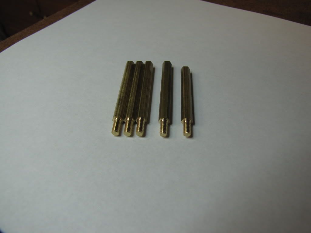
You can see why there’s five pieces there. Another part for the 'shelf of shame'. The one on the right is a boo-boo (a bit short). I measure twice…I really do. But I must be one those ‘3 times the charm’ kind of people. Measure and measure often.

It may be hard to tell, but I forgot to chamfer the 3 threads on the left. The next one was chamfered. There was no problem threading any of them…but I think the 4th looks better.

Now for the fun part. I hope I don't end up adding even more to the 'shelf' and thinking..."yep...should've done the studs". Well...worse thing should be knocking off the threads and doing what Marv suggested. Have to be careful though. To some extent, the columns set the distance between the cylinder and the crankshaft.

 
Nope. Not going to do it. I keep looking at the things and the idea of getting all four to the exact same length just doesn't seem possible...at least not for me. Maybe it's not critical for this engine...but I'm going to go for Marv's suggestion.

I'll try to keep what I have so far though. Maybe use the threaded ends as a way to line up the other ends.
 
I have used the stud method numerous times but rather than using threaded rod which must be cut and ends cleaned up, i use appropriately sized set screws of the length needed. Maybe that's too easy but it makes for a nice end result.

Bill
 
In the time it took me to eat lunch and type the below, I see things have changed again.
Ah, well, in the words of Emily Latella,

[ame]http://www.youtube.com/watch?v=V3FnpaWQJO0[/ame]

As much as people may not like this...I'm going ahead with the instructions. In part because I think there may be more opportunity for practice in getting this to work. You mentioned 'finicky' and sometimes that's a cue to 'work at it'. I'm worried that this may be taken as a sign of laziness - but I think the difference in amount of work is negligible.

Since this engine is a learning experience, I can appreciate your intention to stick with the instructions. (At the least, you'll learn why many of us, most especially me, don't follow instructions.) :)

I hate the process of cutting two or more rods to the same length in the lathe. After removing a rod to measure it, one needs to index the tool tip to the face of the stock after re-inserting it. It's extremely easy to touch off the tool against the stock face with a bit too much pressure and end up cutting the thing too short. For the columns, a difference of a few thou probably won't matter much but for something more demanding I always try to find an alternate approach.

A collet stop in a 5C collet can work in theory but I have had disappointing results in the past (probably my own fault). But you don't have collets yet (I think). On some 3jaw chucks, it's possible to fit a backstop but, even if possible, that's more tool making to draw you away from the project at hand and it may not work with your chuck.

Perhaps you could make a dummy collet. Scrap drilled with a blind hole just big enough to admit the hex bar and fitted with a setscrew to lock stock in place. After machining one end of each hex, mount scrap piece in chuck. The hex could then be inserted repeatedly to a fixed depth. The scrap piece would have to remain in the chuck until all four hexes were machined.
 
Bill...I think the set screw idea is great. I wished I had some. Yet another reason for me to start a collection of various screws, bolts, etc. I have basically nothing. I've seen the good tips of getting only one or two sizes and cutting as needed. Thanks.

Marv...that was great! Good laugh. :big:

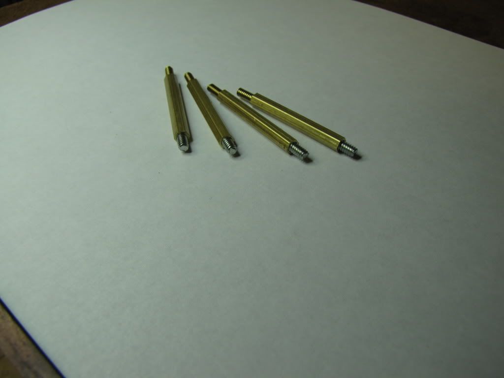
So here's the result...

IMG_0228.jpg


I found some 6-32s in an old junk drawer. I couldn't believe my luck. Right length too...just knocked off the head with a hacksaw.

Ganged the columns and used the mill to bring all to length. Got what I wanted but I think the setup could have been better. (No pic...there many better ways and no one would learn from this...except more about me. :))

Held the column in a V-block and center drilled, drilled, and tapped. Had I the proper tapping tools...I would have done this on the lathe.

Still, they came out good. Now for sanding and polishing. Then it's the long awaited rotary valve......and non-fitting piston.

Rats. Daughter and son-in-law came over. Something about Father's Day.
 
zeeprogrammer said:
Marv...that was great! Good laugh. :big:
Was good, saved it for future use

So here's the result...

Ganged the columns and used the mill to bring all to length. Got what I wanted but I think the setup could have been better. (No pic...there many better ways and no one would learn from this...except more about me. :))

something like this, vertical is the end Mill cutter :)
zee-a4.jpg


Rats. Daughter and son-in-law came over. Something about Father's Day.

They bring Cheese cake?

zee-a4.jpg
 
Carl,

Great progress!

In regards to questions about my post: I'm charging the batteries for the camera and will take some pics. Afterall, a picture is worth 1000 words. No compound on the mill. I was noting that the same method works for the lathe if the compound is set parallel to the ways. Hopefully, I will be able to convey all of this with some pictures. Do you want me to post here or start a new thread?

Bob
 
Foozer said:
They bring Cheese cake?

Are you kidding? They're too young. I have to wait a bit before they realize just how great a guy I am and deserving of goodies. They have no idea I would even want goodies. Idiots. Well HE is anyway. :big: My own Dad is still laughing and enjoying the revenge.

As for the gang...not what I did...wished I'd had the patience to wait.
 
90LX_Notch said:
Hopefully, I will be able to convey all of this with some pictures. Do you want me to post here or start a new thread?

Thanks Bob. No problem posting here - it's a learning thread.

Thanks again.
 
:rant: Time for a bit of a rant.
The instructions say 'they break down the process into the smallest step-by-step procedures to insure [ensure] your success'.
Baloney.
So to mount the rotary table...you use a 'custom holder' for the indicator.
Any mention of how to make that 'custom holder'? Nooooooo.
And then it says..."however, since these instructions are written for the person who is new to the Machinist Hobby, I'll show you how to mount your chuck with the hold down set." Oh har de har har.
This is advertised as a beginner's kit. BEGINNER's. There shouldn't be custom tools in here. If the goal is for the beginner to experience success so that they'll continue...then they ought to make it possible without a lot of surprises. At the least a 'what you need' section should have been included.
:rant: :rant: :rant: and :rant:
Now...having gotten that off my chest...
I need to figure out how to mount the indicator so I can locate the center of the rotary table.
And then I'll mount the chuck.
And then I'll discover there's no room.
And then there'll be another rant.
So the lesson for the newbie thinking about getting into this hobby...either choose a project that's been recommended by someone (you trust) that will meet your needs or...be like me...dive in and take whatever comes your way...it's great fun. ;D
 
zeeprogrammer said:
:rant: Time for a bit of a rant.
...
So to mount the rotary table...you use a 'custom holder' for the indicator.
Any mention of how to make that 'custom holder'? Nooooooo.
... :rant: :rant: :rant: and :rant: ...
I need to figure out how to mount the indicator so I can locate the center of the rotary table.
And then I'll mount the chuck.

Haha, what kind of indicator do you have? There are many types of mounts available, and even more possibilities for fabrication.
Mounting the chuck, chucking on a piece of ground round stock, or gauge pin, or endmill shank, isn't so bad, what am I missing? I'm not picking on ya for ranting. Didn't your indicator come with ANY means of mounting it? Maybe I can send ya something to mount it with... and Guinness. ;D
 
zeeprogrammer said:
Marv...that was great! Good laugh.

Ganged the columns and used the mill to bring all to length. Got what I wanted but I think the setup could have been better. (No pic...there many better ways and no one would learn from this...except more about me.)

Marv...your post deserved more than just a 'that was great'. Thanks for taking the time and effort.

Robert...Your suggestion is certainly better than what I'd done.

What I poorly did was...drilled four holes in a rectangular pattern in a length of 1x1/16 aluminum. Vertically inserted the columns such that two where against each other, some space, and then the other two against each other. Placed in a vise with V-blocks as pusher blocks. Seated them as the vise was closed. Used a square to keep vertical. Milled the tops. If you hadn't gasped yet...you should have. Took too many fingers to keep things aligned.

Unless you gang only against the flats, I believe you'd have problems with one column acting like a wedge. Maybe a simple vise stop (there's that tool again) would have been better.
 
Foozer said:
Rx
Take two and call in the morning

Here's my call...feeling great! Got anything for a headache?

vlmarshall said:
Maybe I can send ya something to mount it with... and Guinness.

Thanks Vernon. I appreciate the offer. (Very difficult to turn down, what with the Guinness - especially as you didn't specify quantity - I have visions of cases).

The only things the indicator came with was a small diameter and larger diameter 1/2" long round thingie that slides onto a dovetail on the indicator. I don't have the bit that goes from that to the chuck or collet. That was the 'custom holder' I was ranting about.

Time to fabricate a holder. While I think on that...I'll tackle the piston problem.

When the piston was made, I test fitted with the cylinder until it slipped on. Now it doesn't. It may be a small burr due to the chamfering that was done after fitting. So I'll try dealing with that first. Otherwise (or in addition to), I'll have to figure out some way to lap the cylinder's bore. The bore is 9/16". Maybe take a 9/16" rod of something and use as a lapper? What kind of material? What kind of polish?

While I think on that...I'll polish up the columns and connecting rod.
 
Carl,

I am going to assume you have a dial test indicator as opposed to a plain indicator because you mentioned the dove tails. I am also assuming that your RT has a center hole that is MT1 or MT2. In the attached pics for illustration purposes only, I put a "boo boo" of a JT33 taper project of mine in the vise. The Test Indicator post is mounted directly into a collet or a drill chuck. The post is located at the far end of the dove tail to get a bigger swept diameter. The Test Indicator's tip is moved to an appropriate angle to allow for the JT33 diameter to be swept. Gently rotate the spindle by hand and adjust x,y until the indicator reads 0 for the entire 360 degree rotation. What I did was to adjust at 90 degree intervals by moving half the indicated distance in the opposite direction and resetting 0 on the test indicator by rotating it's dial.

Note: Watch the movement of the test indicator needle and don't allow it reach it's limit of travel. If necessary make adjustments before 90 degrees of rotation. Also do a "dry run" with the indicator tip above the bore and rotate it 360, adjust x, y to get it concentric by eye before moving the tip into the bore.

I hope this makes sense. The kids are be very needy as I type this and distracting me like you wouldn't believe.

Bob

DSC02389.JPG


DSC02390.JPG
 

Latest posts

Back
Top