Open Column Launch Engine from Kit

Home Model Engine Machinist Forum

Help Support Home Model Engine Machinist Forum:

This site may earn a commission from merchant affiliate links, including eBay, Amazon, and others.
zeeprogrammer said:
Sounds good.

Any chance the stock would get stuck? Not from the loctite but from material from the part your drilling through?

Any chance the stock would gouge the hole when it's removed?

I agree with the rules...or rather...rule. Just not the tequila. But to each their own. ;D

Long as the stock is softer, shouldn't be a problem. Its just to provide some resistance for the bit as it breaks thru, also reduces the amount of displaced metal "volcano,burrs, PIA to clean up" on the exit.

Time to grab my bottle and head to the barn, see what wonderful boo boos I can do today
 
Thanks Vernon!

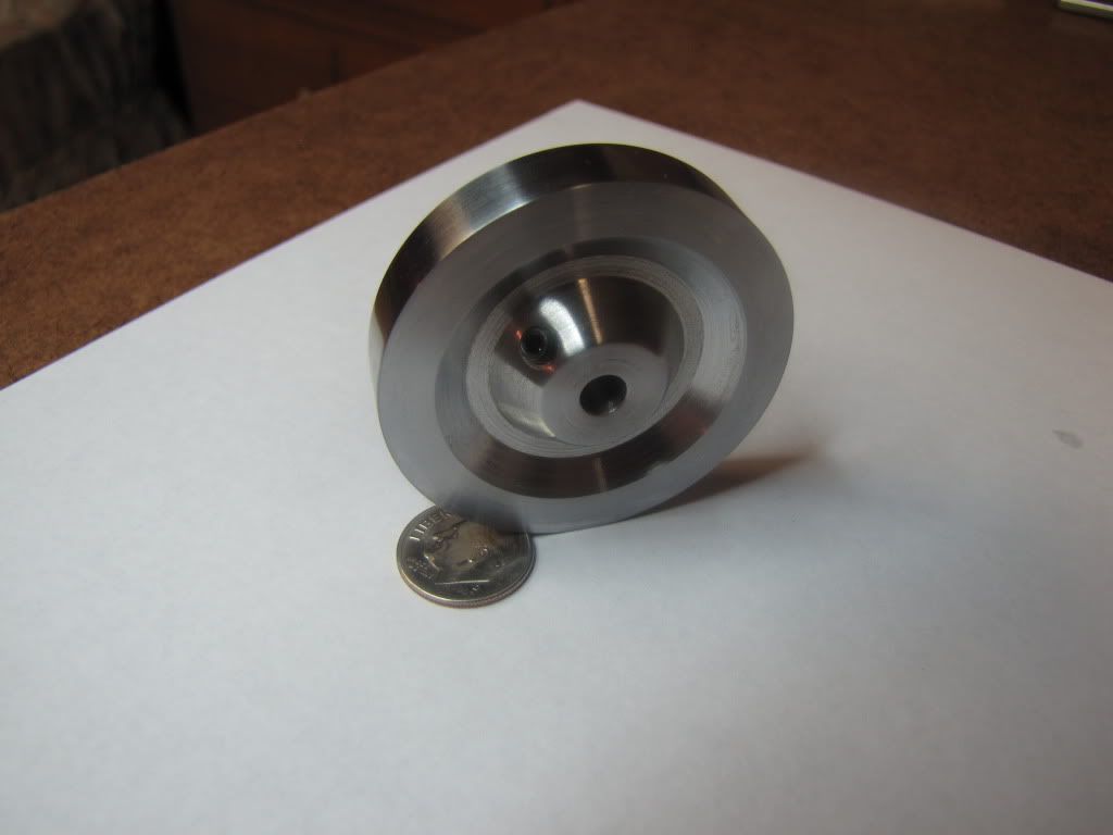
Success! I mean...flywheel success! Still have a way to go on the engine.

Got the last #29 drill bit from the hardware store.

I had removed the flywheel so now the question was...how to put it back the way it was? I put the drill in by hand backwards and used the part sticking out to eyeball vertical. Nothing else had changed so my hope was that this would be good enough.

Very very carefully...very very slowly...(with more TP nearby) I drilled through to the center. Yippee.

Spot drilled with a 3/16 end mill (according to instructions). Then tapped. This would be the last operation. Oh the anxiety. Success! Does the set screw fit? Yes!!!

By the way, the instructions do not tell you how to determine what drill bit to use for what tap. This forum is an invaluable resource.

Polished the sides then used a 7/32 center punch as a shaft and set screwed the flywheel on that. Spun at low speed and sanded polished the outer rim.

Pretty happy. I need a lot more practice and learning on sanding/polishing but I'm pretty happy.

IMG_0210.jpg


Another learning...I shouldn't have tightened the vise as tight as I did. You can see where the metal squeezed out a little on the sides of the rims. It'll take practice to know how much is enough.

Also...I wonder if I should have at least taken a couple of passes turning the diameter down. It would mean flipping the part around and trying to meet the same diameter from the other side. But I think the finish would have been better. Still...pretty happy.

Lots yet to do. Columns, inlet and exhaust pipes, holes to mount the cylinder cap...and sanding sanding sanding (it's the only method to hide my boo-boos, no painting on this project).

Thanks again everyone. There's a little bit of you in this build (but not the mistakes - those are all mine baby). ;D
 
zeeprogrammer said:
Thanks Vernon!

Success! I mean...flywheel success! Still have a way to go on the engine.

No double shot for you :)

Also...I wonder if I should have at least taken a couple of passes turning the diameter down. It would mean flipping the part around and trying to meet the same diameter from the other side. But I think the finish would have been better. Still...pretty happy.

Can mount flywheel on a mandrel (think that's the term) and run between centers, more accurate than the 3-jaw. Also allows for the slight skimming of the surfaces to remove any wobble, not that such a thing as wobble happens :)

Small pic as example, dog is missing from mandrel, just an example shot

zee-a2.jpg
 
Well this might be (will be) a longish post.

As you all may have noticed...I've had the opportunity to do nothing but machining for the last two days. No one in the house...I'm all alone - aside from the great people on this forum. (Great so long as they don't deny me my little rewards - eh Robert?)

Time to finish the cylinder…

A port hole on the side, 6 holes on one end for the cap, and 4 holes on the other end for the columns.

The drawing shows ‘TAP DRILL - .38 DEEP’ and then ‘#8-32 THRU ONE WALL’. The wall is only about .21 thick so I don’t understand why the ‘.38 DEEP’. Is it a standard way of calling out for TAP DRILL operations?

The drawing also calls for a 7/32 (0.22) spotting operation (end mill?) which I don’t have. I’ll use 0.25. Operation calls to mill until a full circle is shown – acts as a face for the port pipe to seat against. Too far and you take away thread.

First the port hole. It’s used as a reference to locate all the other holes. Otherwise I might (and I would) drill a cap mounting hole through the port hole.

IMG_0211.jpg


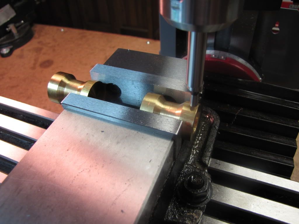
The cylinder’s ends don’t straddle the empty area in the middle of the vise so it has to be mounted to one side. As Vernon suggested…I have another piece on the other side of the vise in order to apply even pressure.

This is the second time a failed first part has come in handy (and another reason to keep a ‘shelf of shame’).

And now we see another consequence of changing something with insufficient understanding of the consequences. The 0.25 end mill is too big.

[EDIT: Also, I should have probably done the spot first then drilled the hole. If anything it might have pointed out if something walked on me. If you notice, the spot is offset from the hole.]

IMG_0212.jpg


I trial fitted the cap. Nice! No play at all and the outer edge is even with the cylinder’s outer wall. I’ll probably keep it mounted when I get to finishing the cylinder’s wall.

Question: I was hoping to simply sand the outer wall to finish. If I wanted to do some light turning to get rid of deeper blemishes…any reason why I couldn’t do that with the cap mounted so both would be turned to same diameter? (Foo. I probably should have done this before I did the port hole in the side.)

Now for the holes used to hold the cylinder cap. Instructions are a bit confusing here. First operation calls for setting the cylinder cap in place and doing a center drill (while holding it with a finger!). Then remove the cap and drill/tap the 1st hole in the cylinder. Then change to the clearance bit for the cap, bring the head down (no power) until the bit comes into contact with the thread and set the z stop. Put the cap on and drill through it (holding it down with an eraser!) Screw the cap down and do the other holes.

1) I’m not sure there’s room to tap without moving the table.
2) Instructions didn’t say to do all the cylinder holes first.
3) Why bother with the 1st center drill on the cap?

Well we’ll see.

First thing is to find the center of the cylinder. Should already have the y direction. So use the edge finder inside the hole or outside? I’ll go for outside…it should act more like a straight edge to the finder than the inside. (Yet another opportunity for better ideas from others.)

Actually…maybe this is better…measure diameter with caliper, take half and add 0.1 from the edge finder. Then I’m coming in from just one direction.

Question: Supposed to drill 0.38 deep. I thought for best accuracy, all operations are done at one place before moving. The operation is center drill, then drill (and if I had the proper equipment…tap). How do you ensure the same depth for each operation? I was going to use the Z stop…but if I’m changing the drill bit out every time…I’d have to change the Z stop every time.

Wish I had some digital read-outs on the table. That’s a mod that’s coming.

I still don’t understand the instructions. Going to do the cylinder holes first. Then I’ll do the cap. I can still use the cylinder as a reference for setting the z stop before doing the cap. For the cylinder holes, I’ll use a digital caliper to see how far I’m drilling. I do this by setting the caliper on top of column and measure to the top of the head. Zero it and watch while I slowly drill down.

I’m thinking backlash is going to add some inaccuracy but I don’t think these holes require it. Still…I need to learn better practice.

So stay tuned for an edit if/when someone points out my evil ways.

I also need a better way to tap. Doing it all manually right now. There’s tap handles suited for the mill/lathe that help keep things square.

Drilled the six holes. Able to tap without moving anything.

IMG_0213.jpg


Moved to one of the holes.
Put in the clearance bit for the cap.
Set the z stop.
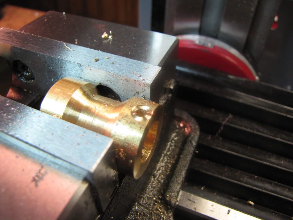
Then CAREFULLY held the cap on and drill a hole.
It helps that the cap has a shoulder and seats on the cylinder. You just have to press down. (I still don’t like this…certainly not as a beginner’s kit.)
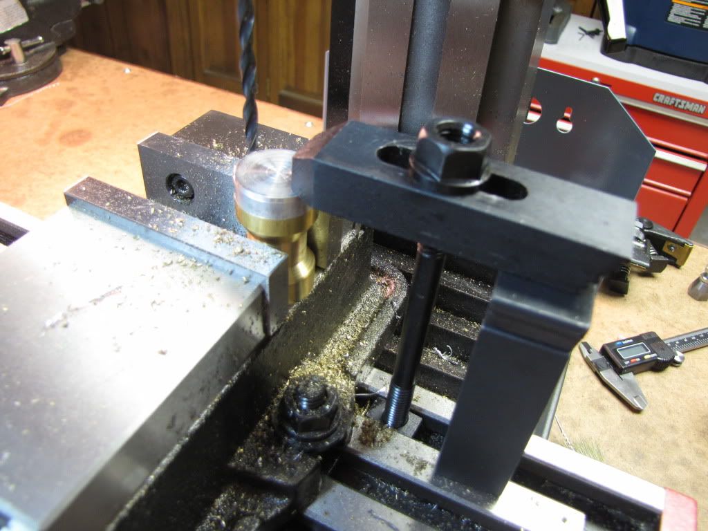
[EDIT: If you're uncomfortable with the instructions...find a better way. Having my finger there really bothered me...and as expected...a couple of fine members pointed this out to me. Had I thought more about what I was trying to do and how I might do it...I might have come up with this to do the first hole...]

IMG_0220.jpg


[EDIT: I am slowly learning that the clamping kit is your friend.]

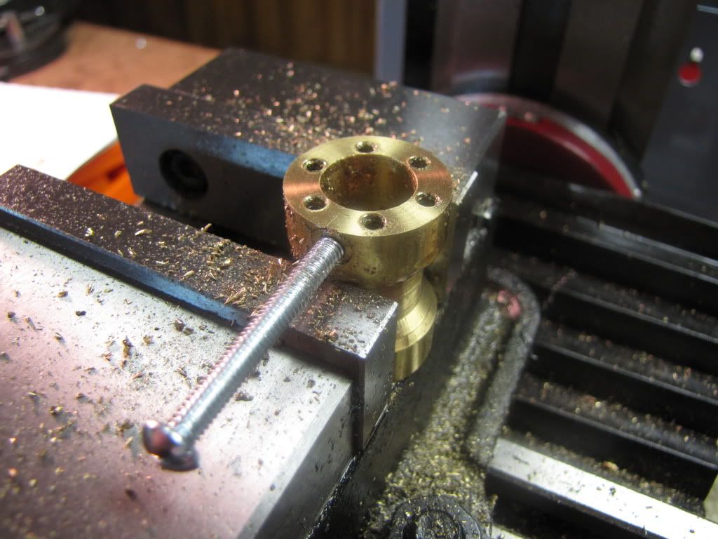
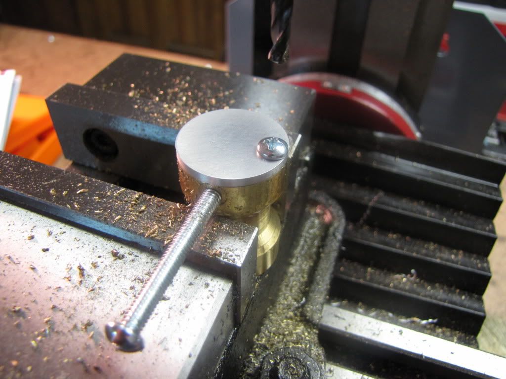
Then screwed it down.

IMG_0214.jpg


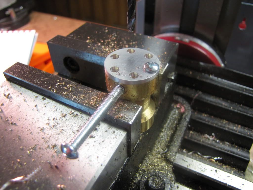
Then did the other holes.

IMG_0215.jpg


Now for the bottom 4 holes. No pic. It's just the same stuff. But the bolt is on the bottom now and sticking out to the right.

Sanded the cylinder and cleaned it up.

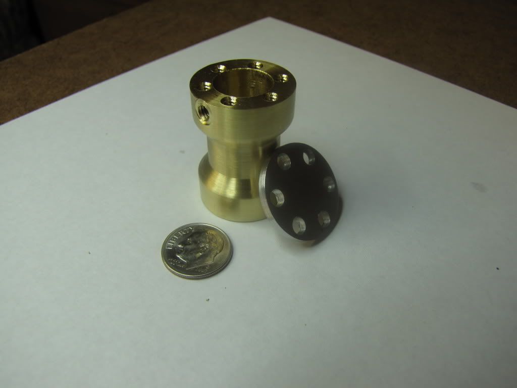
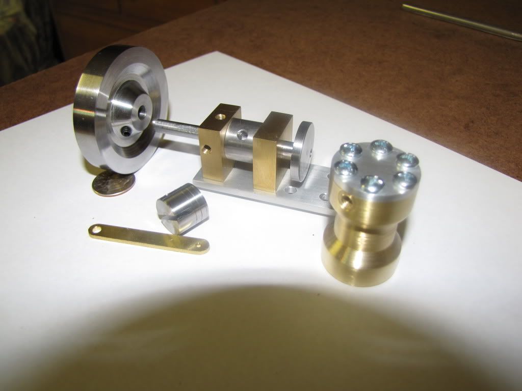
The cylinder and cap...

IMG_0216.jpg


Where I'm at now...

IMG_0218.jpg


Still have the columns, input/exhaust ports, and cleaning up of the connecting rod.

The rotary valve still needs some grooves for which I have to use the rotary table. I'm saving that bit for last...never used the table.

And then there's the problem of the piston. It don't fit. It fit when I turned it down and put the cylinder on it. But it don't fit now. Well we'll see.

Again...thanks to everyone for their advice and tips. Thanks to everyone for reading this beginner's trials and tribulations.

I look forward to the advice and/or remonstrations for this post.

Ha! Foozer. I started celebrating when I started this post. Now I've celebrated enough that I have to stop. :big:

 
Carl,

Doesn't your Z fine feed collar have a scale on it? Should be .050 or .062 per rev like your x and y collars. One way to do the depth for multiple holes with Z stop would be as follows:

1) Zero the tool on the part.
2) Back the Z axis to clear the part.
3) Move X or Y to clear the part.
4) Use the fine feed on Z and adjust Z (tool) to the required depth.
5) Set the Z Stop.
6) Back the Z axis to clear the part.
7) Set X, Y to hole location and drill until Z comes in contact with the stop.
8) Repeat steps 6&7 for each hole.

You can also set your longitudinal travel for your lathe in the same manner using a stop if the compound is set parallel to the ways.
If this is unclear let me know and I'll take some pictures and post them up.

Bob
 
90LX_Notch said:
Doesn't your Z fine feed collar have a scale on it? Should be .050 or .062 per rev like your x and y collars. One way to do the depth for multiple holes with Z stop would be as follows:

1) Zero the tool on the part.
2) Back the Z axis to clear the part.
3) Move X or Y to clear the part.
4) Use the fine feed on Z and adjust Z (tool) to the required depth.
5) Set the Z Stop.
6) Back the Z axis to clear the part.
7) Set X, Y to hole location and drill until Z comes in contact with the stop.
8) Repeat steps 6&7 for each hole.

You can also set your longitudinal travel for your lathe in the same manner using a stop if the compound is set parallel to the ways.
If this is unclear let me know and I'll take some pictures and post them up.

Yes! But doesn't that assume I'm not changing the tool and therefore not the Z? That was my problem.

If I center drilled all spots and then drilled all spots...I think I could have done what you suggested (if I'm understanding it right).

But if I'm changing the tool every time...that is...center drill, change to drill, drill, then change to center drill...my Z value would be different every time.

Also, you mentioned 'compound' which I understand on the lathe...but not the mill.

So yes, I'm confused and pics would help.

Oh and you're right...the scale is 62.5 for x, y, and z. I'd like to know why. It's inconvenient on one hand, but being a multiple of 1/16 is handy on the other hand.

Thanks Bob.
 
zeeprogrammer said:
Well this might be (will be) a longish post.

As you all may have noticed...I've had the opportunity to do nothing but machining for the last two days. No one in the house...I'm all alone - aside from the great people on this forum. (Great so long as they don't deny me my little rewards - eh Robert?)

Rewards? Plural 1 double = 3 singles Yup, my mechanics math is correct

And now we see another consequence of changing something with insufficient understanding of the consequences. The 0.25 end mill is too big.

Looks like its a tad off center, could be the light, or the double's are blurring my vision :)

Now for the holes used to hold the cylinder cap. Instructions are a bit confusing here. First operation calls for setting the cylinder cap in place and doing a center drill (while holding it with a finger!). Then remove the cap and drill/tap the 1st hole in the cylinder. Then change to the clearance bit for the cap, bring the head down (no power) until the bit comes into contact with the thread and set the z stop. Put the cap on and drill through it (holding it down with an eraser!) Screw the cap down and do the other holes.

I'd use something other than a finger, center drill, odds are it wont catch and spin the part, but having a finger that close to what could be a sudden rotating object is not the best habit to develop. It hurts a lot more when you quit squeezing the finger with one hand muttering those colorful words for the neighbors to hear and take a look at the source of blood flow. And when the bride just has to tell everyone about her hubby's brilliance . . .

The operation is center drill, then drill (and if I had the proper equipment…tap). How do you ensure the same depth for each operation? I was going to use the Z stop…but if I’m changing the drill bit out every time…I’d have to change the Z stop every time.

Piece of tape around the bit? works so-so. I've made little drill stops to fit the bit. Have to be diligent to clear the chips as the stop tends to act as a dam.

I also need a better way to tap. Doing it all manually right now. There’s tap handles suited for the mill/lathe that help keep things square.

just search the board for the subject, lots of methods. Got some real fancy tapping stands shown herein.

Ha! Foozer. I started celebrating when I started this post. Now I've celebrated enough that I have to stop. :big:

Monterrey Jack and Cabernet?

Robert
 
If I center drilled all spots and then drilled all spots

That's the best way.

The instructions are one way of ensuring that the holes in the cap and cylinder match up. Since the clearance hole in the cap and the tapped hole in the cylinder are different sizes, you need to ensure that the cylinder holes aren't too large. I think I would have drilled the cap holes first with the tap drill through to the cylinder, and then enlarged the cap holes separately.

If you have a DRO or accurate dials and edgefinding it's certainly fairly easy to position and drill the cylinder and cap separately.
 
Foozer said:
Looks like its a tad off center, could be the light, or the double's are blurring my vision

I'd use something other than a finger...

Monterrey Jack and Cabernet?

Off center...you're right. I hadn't moved anything...I just swapped the drill chuck for a collet and end mill. So I was a bit surprised. Any thoughts? I don't believe I bumped the table and the offset seems to be more than backlash could explain.

Yes...the finger use really bothered me. I struggled between trying to follow the instructions (other beginners will be building this) and doing what I (a newbie) thought better.

Jack and Cabernet? Great idea but I only have the crackers right now.

kvom said:
I think I would have drilled the cap holes first with the tap drill through to the cylinder, and then enlarged the cap holes separately.

If you have a DRO or accurate dials and edgefinding it's certainly fairly easy to position and drill the cylinder and cap separately.

Yeah I thought about doing it separately. Accuracy wasn't critical (at least for the cap). But my question here is how to hold the cap? When I did the cylinder cap for my first model, the vise crushed the sides in a little.

With everyone's comments and the light of day...I think what I should have done is used the clamping kit to clamp the cap down onto the cylinder...do one hole...and install the screw...then remove the clamp and do the rest.

Here's a mock-up...

IMG_0220.jpg


Thanks Robert and kvom.

I'm going to edit the post.
 
zeeprogrammer said:
Off center...you're right. I hadn't moved anything...I just swapped the drill chuck for a collet and end mill. So I was a bit surprised. Any thoughts? I don't believe I bumped the table and the offset seems to be more than backlash could explain.

Yes...the finger use really bothered me. I struggled between trying to follow the instructions (other beginners will be building this) and doing what I (a newbie) thought better.

Jack and Cabernet? Great idea but I only have the crackers right now.

I'm going to edit the post.

Zee, dont take anything I say as if I'm ragging on ya. I have a Devils Advocate nature and tend to forget some of the social rules.

I get split on edits, but I'm fairly even across the board on visual, audio, and tactile interpretations. A photo of a "wrong" way is often as valuable as the "right" way. Other side is not everyone reads the whole verse and plunges headlong into disaster. With the center drill, hold part down with finger, I personally, in an act of shear genius would do have done it that way, but raise up a storm if I saw my kids doing it.

A piloted counter bore HERE keeps the cut on center, but again that's more tooling, more $$$ and at some point, unless you got the winning Lotto numbers, becomes just plain silly for a hobby. End mill should be able to cut the recess, a 2 flute I think is the type, have only seen that you have 4-flute versions. I think and someone chim in that has more experience on the subject, I would of cut the recess first and then the bolt hole. Five it a shot on your scrap piece. Looks like a 0.015 thou offset so something walked, Looks good to me.

Crackers? as in Going!


Dont see any pieces of soda can 'tween that nice cylinder and vise jaw, irony of the edit ;)
 
Foozer said:
Zee, dont take anything I say as if I'm ragging on ya.

Huh? I thought everything you said... ;D
No not at all. I appreciate everything you've said. Thanks.

As for 'the finger'...I mentioned it earlier...poor practice should be pointed out...not just for the 'practitioner' but for any newbie who might be reading this.

Yes, I should've done the spot first. Instructions seemed to indicate otherwise but I think you're right.

I do have 2 fluted end mills. I haven't learned yet when to use one over the other. I've been a 'loyal' (read 'biggish spender') at LMS so you might know the ones. The boxed set of 4 and 2 fluted end mills from 3/16 to 3/4.

I'm thinking some one's going to tell me to use 2 flute for plunge cuts?

Dad blast it...soda can pieces. Of course. No soda cans here but if I can't come up with an obvious alternative...I don't deserve being here. ;D

Thanks Robert.
 
I'm beginning to think you should throw the instructions away. Hold it with your finger? Holy &@#$ ! Who wrote these instructions? A hand surgeon trying to drum up business?

Here's a better approach - an expansion on what Kvom has already advised.

Superglue (cyanoacrylate) the cap to the cylinder. (Degrease mating surfaces with acetone or carburetor cleaner before gluing.)

Drill and tap all six holes right through the cap. Tap each hole immediately after drilling it. (Make one of the guided tap holders I've shown to do this job, perhaps.)

Remove cap (soak in acetone or heat with torch until glue breaks down)

Open up holes in cap to appropriate clearance size. Hold the (too small to hand-hold) cap by clamping it to a piece of scrap while you drill the clearance. (A clearance hole size isn't critical and the drill will want to follow the existing hole anyway.)

If you do a good job laying out the six holes, the cap should fit in all orientations, especially so given the "wiggle room" afforded by the clearance holes. Nevertheless, you may want to make an inconspicuous witness mark on the cap and cylinder before separating them so you can get them back together in the as-drilled orientation.
 
mklotz said:
Hold it with your finger? Holy &@#$ !

you may want to make an inconspicuous witness mark on the cap and cylinder before separating them so you can get them back together in the as-drilled orientation.

Aw man...I was hoping you wouldn't catch me. :(
The post has been suitably (I hope) edited.

Great tip on the witness mark. Thanks.
 
I had started the hose couplings and exhaust pipe early on but when I realized the die I had was not appropriate I went on to other things.

As other members had pointed out (and some internet research also indicates), the die I had (hex shaped) is intended for re-threading and not for cutting new thread.

I got a round adjustable die and tried it on the piece I had started. What a difference! So much easier. I finished one hose coupling and the exhaust pipe. The exhaust pipe only differs in diameter (a bit larger) and a slightly larger hole on one end for half the length.

So now for the other two hose couplings (all 3 are supposed to be identical)…

The general idea is to make two parts out of one piece. Turn each end down to size for a little over length. They don’t have to meet in the middle as the piece is somewhat longer and will be parted at that point. Then use a small parting blade (the one I made out of a hack saw) to cut a groove for a thread relief. Turn the end down for the thread. Cut the thread. Turn the part around and do the other end. Bore the hole through. Then part one piece off and trim the other to size.

When I tried my new die on the first piece…I hadn’t parted it yet. So it was nearly 1.25” long. I fitted it to the port block to see how the thread did. It fit well but I noticed it was at a very slight angle. (It’ll look better when it’s only half an inch.) But the lesson here is that, as careful as I was to tap perpendicular to the block…I was off. I need to get/make tapping tools to ensure the tools are held square.

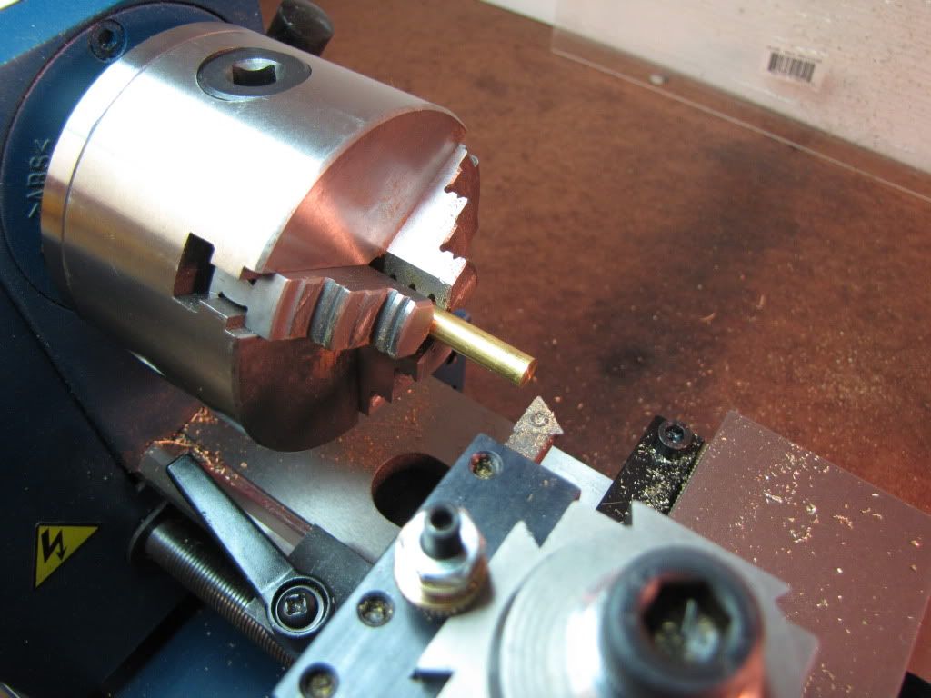
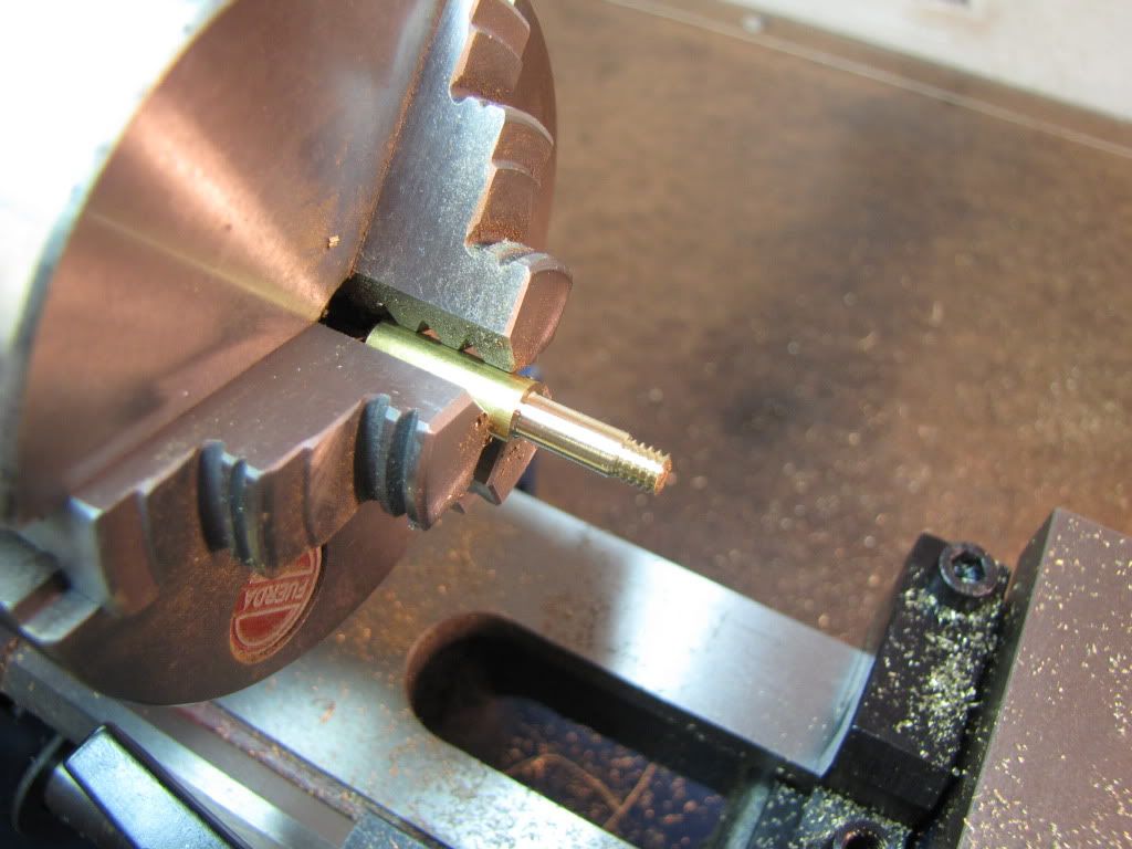
Chucked and ready…

IMG_0221.jpg


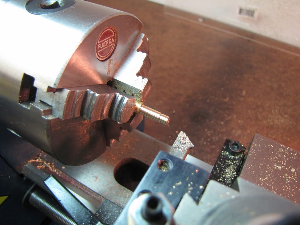
Turned, grooved, and turned the end down further. Then a small chamfer in preparation for threading.

Made use of the carriage stop and getting comfortable with zeroing the dials and using them. But I’m getting suspicious that something’s off. Crank distance doesn’t seem to agree with caliper. (So I do a lot of stopping and measuring.) This is another area to work on after the project.

IMG_0222.jpg


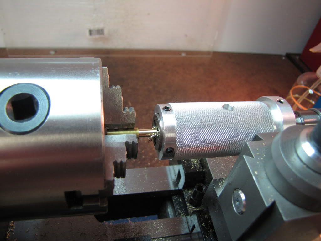
Threaded. I turn the switch off, speed control to 0, and lock the emergency switch down to ensure the lathe won’t accidently turn on. I use one hand on the chuck to keep it from turning and the other hand turns the die holder. Then turned the thread around and threaded up to the shoulder.

IMG_0223.jpg

IMG_0224.jpg


Then turned the part around and chucked holding onto the length that I just did. Repeated the turning/grooving/threading operation.

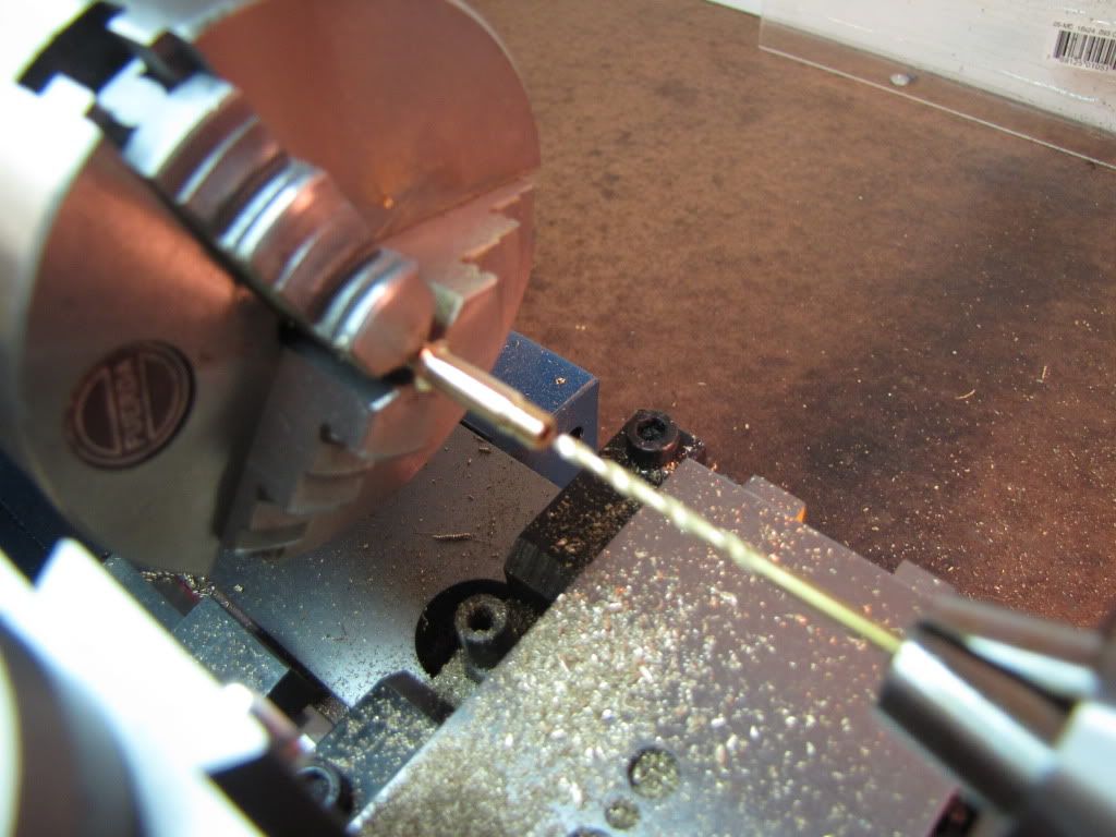
Then drilled it. Peck peck peck…

IMG_0225.jpg


Parted the one off then trimmed the other to size.

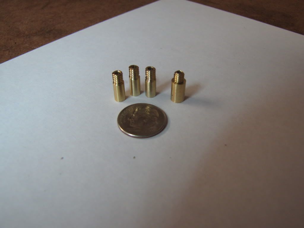
Here they are…the one on the right is the exhaust port.

IMG_0226.jpg


Now I'll just duck under here and wait for what comes... :hDe:
 
Now for the columns.
That's right...still putting off grooving the rotary valve (and there's that pesky non-fitting piston too).

I have one piece of hex brass and need to make 4 columns. Each end of a column has a 6-32 thread on it, one a bit longer than the other.

I'm thinking this...

Chuck the long piece leaving enough out to make the thread.
Turn to size and thread the end.
Move the piece out enough to part off the column and part it.
Repeat for the next two columns.
On the last piece, after threading the end, turn it around and trim to size.
Now I have 4 columns each with one end threaded.
Now turn and thread the other end of each column.

Questions...

1) Any concern about the 8" or so turning round inside the head?
2) If I actually get all four columns to be the same length (shoulder to shoulder) I'll be greatly surprised. Any suggestions to improve my chance of success?
3) Any other suggestions? (Just trying to avoid getting caught again. ;D)

Thanks.

 
But the lesson here is that, as careful as I was to tap perpendicular to the block…I was off. I need to get/make tapping tools to ensure the tools are held square.

Yes, you do. (I hate saying I told you so.) Ensure that they're piloted too. In addition to keeping things straight, you'll break far fewer taps.

I know that, when just starting out, it's very frustrating to have to interrupt the project to make needed tooling. However, it needs to be done. Part of the zen is to learn to obtain satisfaction from using the tool to get something "just right". The real satisfaction comes later when you reuse the tool and pat yourself on the back for taking the time to make it so it's available whenever you need it. Besides, it'll take you only a couple of hours to make a guided tap holder.

Even by reversing the die, it's often impossible to get a complete thread right up to a shoulder using a die. The coupling/exhaust fittings may not seat fully on the shoulder when you screw them into their mating holes. Take your hacksaw blade cutoff bit and cut away the thread right next to the shoulder down to the minor diameter of the thread. Voila, (not viola, the musical instrument - the constant misspelling of this word is one of my personal annoyances and) they'll seat flat on the shoulder.
 
I really like watching your progress Zee. Like everyone else, I've lost my respect for the instructions you're following with that finger hold-down trick. :eek:

Still, it's great to see your engine gaining pieces, and you not losing any.


Now, for turning the columns to equal length... could you face them to length in the mill first? Alternately, what about making a part stop for your lathe that locks inside the spindle tube?
Something like one of these:
http://www.sherline.com/tip9.htm
http://www.jfberns.com/spindls.htm
...or the one at the bottom of this page, that fits from the chuck end:
http://stevewithnell.wordpress.com/
 
mklotz said:
I hate saying I told you so.

'told you so' is very acceptable on this thread.

mklotz said:
The real satisfaction comes later when you reuse the tool and pat yourself on the back for taking the time to make it so it's available whenever you need it.

You're absolutely right. I'm done tapping on this project...but the lesson is learned.

mklotz said:
The coupling/exhaust fittings may not seat fully on the shoulder when you screw them into their mating holes. Take your hacksaw blade cutoff bit and cut away the thread right next to the shoulder down to the minor diameter of the thread.

Great tip. Thanks. There was a thread relief built into the drawings for the coupling/exhaust. We'll see if it was enough. But the columns didn't show that for the end that goes into the cylinders. I'm just starting on them so the tip is very timely. The other end of the columns first goes through the base before a nut is placed so I don't think it's needed.

You mentioned 'ensuring the tools are piloted'. What does that mean? Is that where the end opposite to the business end has a hole or dimple so it can be held by a center or such?

Thanks Marv.
 

Latest posts

Back
Top