Open Column Launch Engine from Kit

Home Model Engine Machinist Forum

Help Support Home Model Engine Machinist Forum:

This site may earn a commission from merchant affiliate links, including eBay, Amazon, and others.
zeeprogrammer said:
Geesh...I wonder how long the 'newbie-ness' lasts?

Probably forever, well at least in my case, I like to learn something new everyday.


Best Regards
Bob
 
vlmarshall said:
...when you're only clamping a part with one side, it'll close further on the empty side, pinching your part at only one point,
Ah you're right Vernon. I'd read that somewhere...maybe here.
Thanks.


"Geesh...I wonder how long the 'newbie-ness' lasts?"

Robert and Bob...I don't mind the challenges and learning everyday...it wouldn't be fun otherwise...just wondering about the day, when the frequency of 'oh...that was dumb', will drop a little...it will won't it? A little? :)
 
Foozer's advice to turn the piece and then clamp in the v-block is the right idea in my opnion. However, it seems that your hole and the slot need to be perpendicular, so if you have to reclamp it may be difficult to get the position exact.

What I would do is the following:

1) Turn stock to finish dimensions

2) Use the clamp that comes with the v-block to clamp the piece into the V. Leave enough stock protruding from the end of the v-block to cut the slot without moving the stock.

3) Clamp the v-block in the vise. It will need to be sitting on parallels high enough to clear the v-block clamp (i.e, the V of the block is vertical). Position it in the vise so that the exposed stock is clear of the end of the vise jaws.

4) Drill the hole. Use cutting fluid and peck to remove the swarf.

5) Cut the slot.

If you do not have the clamp but do have a second v-block then clamp the piece between the two blocks.
 
Turned down to where I was comfortable enough I could sand to fit.
Sand, polish, clean (both piston and cylinder), wait to cool, fit…repeat.
Kept a paper towel under the work to capture grit.

IMG_0195.jpg


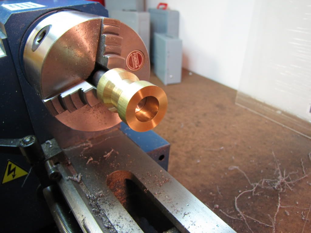
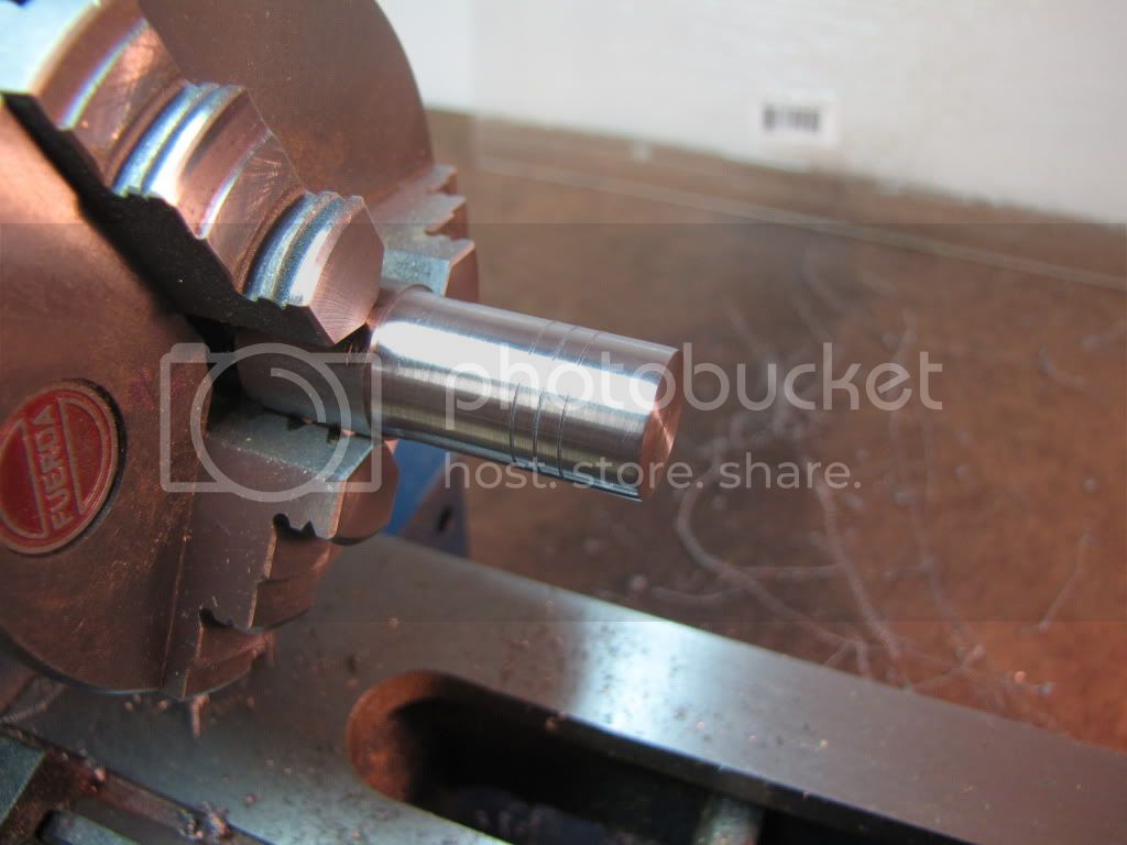
Now for grooves. I don’t think placement is critical but want the groove depth and spacing between to be right. Used my threading tool. Started at the right, zero’d the crank and moved left 0.29. Then moved in the cross slide until it just touched. Moved in another .005. Then back out…move down 0.09 and do the next groove. Repeat again another 0.09 down.

[This was another mistake I had made on the first part. I had moved in 0.0025 thinking ½ diameter. But the drawing shows 0.005 in from the outside. 0.005 is what I want. I hadn’t realized this until I started this operation.]

Touched with scotchbrite to knock off the burrs. Need to remember to be careful and make sure it’s cleaned up before putting it into cylinder and gouging.

Pretty soon I’ll be back to the ‘bit breaking’ point. If successful…it’s lunchtime…else it’s more waterworks.

IMG_0196.jpg


Alright then…

The slight ‘step’ on the piston material is because I turned down with one tool (carbide) and then switched to another tool (HSS). The 2nd tool couldn’t fit as close to the chuck. I ground the HSS tool per Marv’s suggestion. Still not good but at least it’s more practice. No, I don’t know why I switched tools. Practice? Yeah…that’s it…practice. [EDIT: Not the step out to the unturned diameter...but near there. Between the 'good' end and the significant shoulder.]

Now for the wrist pin. Will it be lunch? Or will our hero have another cry?

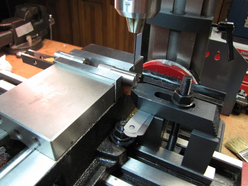
The setup…

IMG_0197.jpg


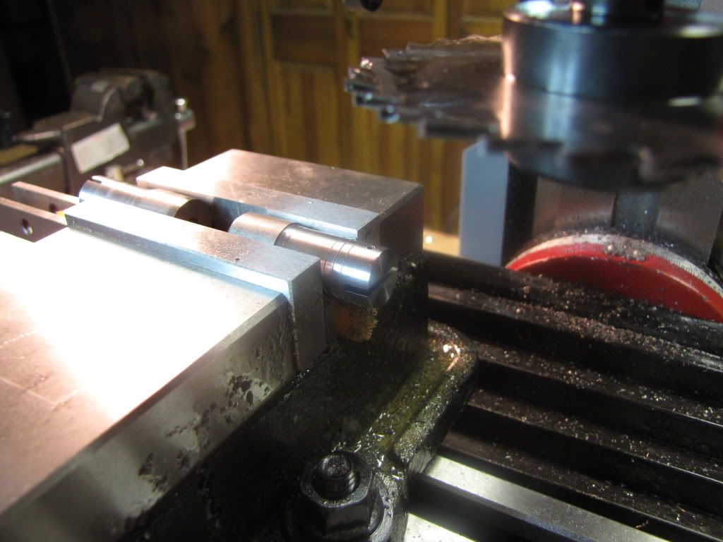
The result…our hero eats!!!

(Missed a pic...drilled, removed the clamps because they're in the way, then slotted.)

IMG_0199.jpg


Thanks to everyone…(I’d list them but there’s a bunch and I’m sure I’d miss someone…but you know who they are ( ;D))

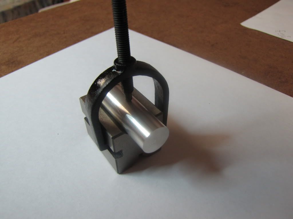
Kvom…didn’t see your post until I went to look for who to thank. But…I don’t see how that helps hold the end up while drilling? Also…I don’t have a vise stop. I worried that the v block clamp wouldn’t have enough oomph to keep the part from moving –x. Here’s a pic of what I think you were describing. (It has a piece of alum…but imagine one end has a bigger diameter that the end of interest.)

IMG_0198.jpg


A small confession…
The instructions called for drilling and reaming the wrist pin hole to 0.0625 (1/16). I didn’t have a 3/64 bit so for the first try I used the closest thing I could find…a #56. With that gone I didn’t have anything else to use. So I used a 1/16 bit. No point reaming. So the question is…just keep going as is? Or loctite the pin into the piston? My problem with the latter is there may be a good chance of loctiting the connecting rod. Don’t want to do that. So I’m thinking the former.

Remove slit saw now. If it’s left in…it will be forgotten and someone (me) will reach by and …owie.

Now it’s time to part it off. First a little cleanup on the wrist pin hole etc.
After cutting in a bit, (and the part is still being held) chamfer the end with a triangle file.

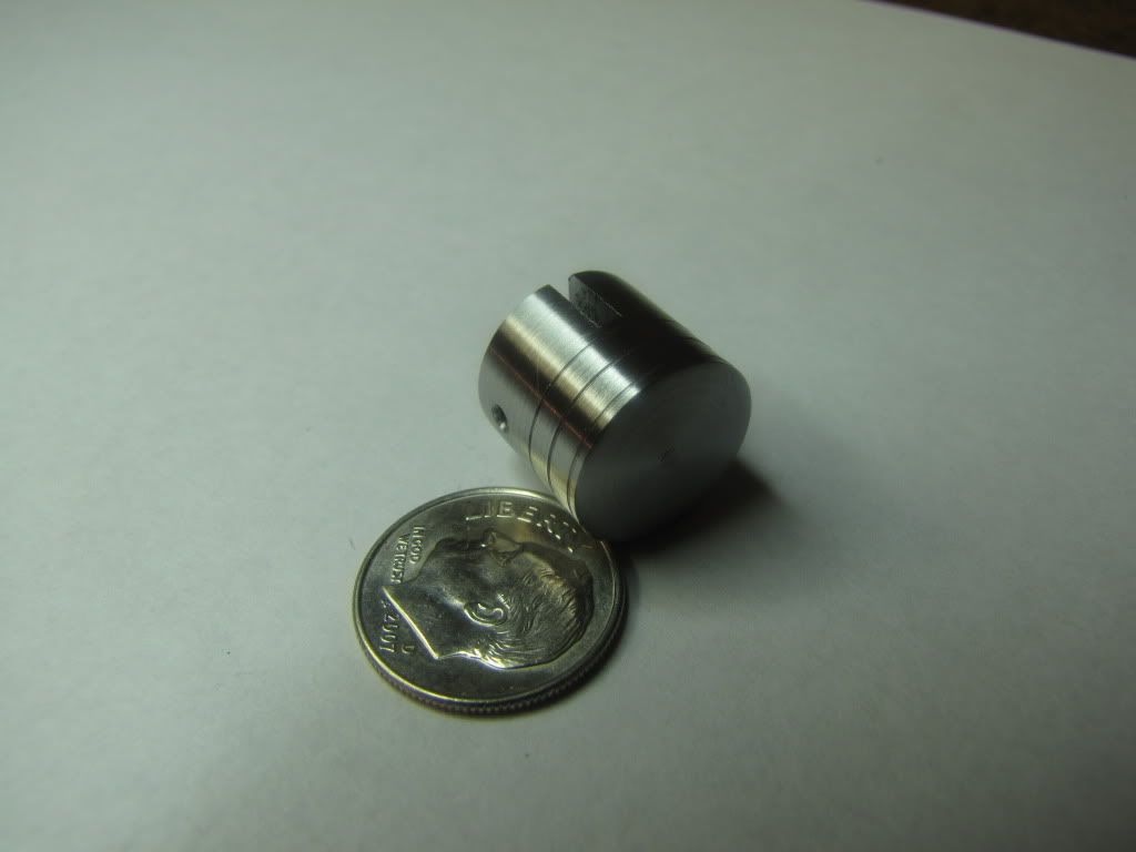
I still find parting to be difficult and scary. Stalled the lathe a couple of times. While the instructions didn’t say to do this…I cut down to a diameter where I felt I could relatively easily snap the part off. Then I chucked the part in and carefully knocked the nib off with my facing tool. Didn’t want to face because there’d be no way I could get it square. The parting did a decent job…so I sanded…and to quote Marv…”voila”…

IMG_0201.jpg


woohoo1 (The peak)

Do it still fit the cylinder? Of course not.

Bummer…(The valley)

Most likely burrs…it’ll get there.
 
Congrats Zee. Great job! Way to stay at it. Thm:
 
Zee,

Way to go. :bow: :bow: :bow:

Best Regards
Bob
 
Thanks 90.
Thanks Bob.

Started the flywheel.

Have to replace the normal 3 jaw chuck jaws with the reversed ones.
Each jaw has a number on it 1,2,3.
Need to replace 1-1, 2-2, and 3-3. Replace them one at a time...else lose my place.

My little trick (yes…I have one…although it might not really belong to me).
I apply pressure to the 3 jaws with one hand and turn the chuck key with the other in the direction of opening the jaws.
As you do that, each jaw will pop in a little. When all three are the same distance from center…then I reverse direction and close the jaws.

Took the opportunity to clean the jaws and chuck a little while I had it apart.

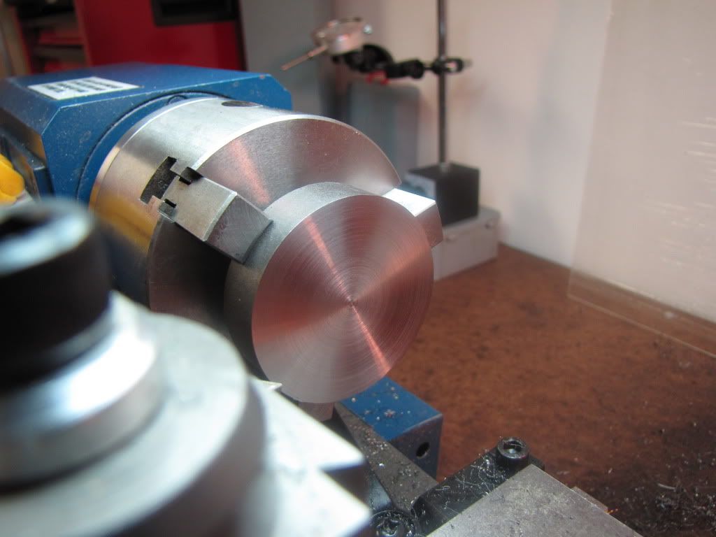
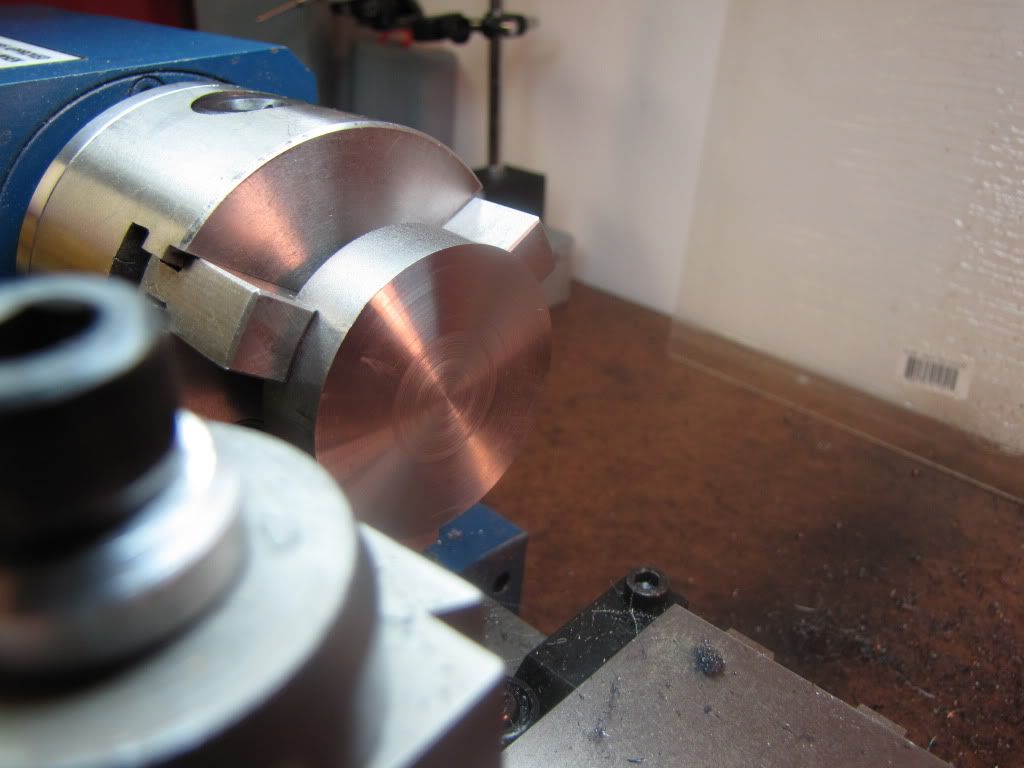
Chucked the flywheel and tried to make as square as possible. Can’t push the flywheel against the jaws since the faces aren’t square.

Faced one side then flipped over. Now (according to instructions) I can set the flywheel up against the jaws.

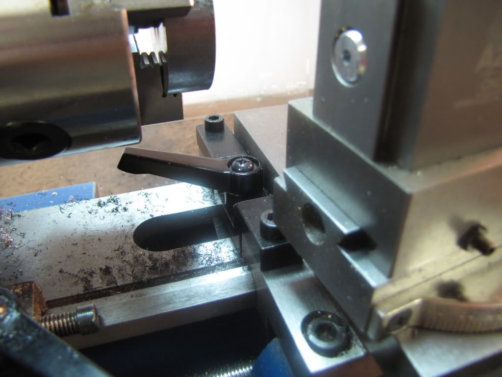
Holding the carriage wheel…hot chips burning me. So I installed the carriage clamp. Not sure about the lever though. I may remove it and use it as a wrench. There's not much travel so turning it back a quarter turn may not be enough to free the carriage. We'll see.

IMG_0202.jpg


The flywheel is 2” in diameter. I notice that as I face, the surface looks great…then when I’m about ½” out from center…a change occurs and stays that way to center. Two different finishes.

Why?

Got my 6-32 and 8-32 dies today!! Woo hoo.
Ah but there's a flywheel in the lathe.
(A fly in the ointment? Was that bad? That was bad.)

Time to take a break...


zeeprogrammer said:
The flywheel is 2” in diameter. I notice that as I face, the surface looks great…then when I’m about ½” out from center…a change occurs and stays that way to center. Two different finishes.

Why?

Zee,

My take on why different finishes across the face.

As the tool moves from the outside towards the centre of the job, the cutting speed in fpm is constantly reducing whereas the feed rate remains the same. The finish changes when the tool cannot cope with the reduction in fpm past its' tip at the constant rate of feed. To overcome this, increase the rpm or reduce the rate of feed if the finish is worse.

Best Regards
Bob
 
Congrats, Zee, that piston looks great! :bow: I'm feeling project envy now. ( No fair, yours is bigger'n mine.)


Anyway, Maryak is correct about your facing surface finish. Can you increase spindle speed as you reduce your cutting diameter? Perhaps the flywheel has a few surface features you can cut in three passes, at three suitable speeds; a raised hub, a dished area, and a raised rim?
 
Maryak said:
As the tool moves from the outside towards the centre of the job, the cutting speed in fpm is constantly reducing whereas the feed rate remains the same. The finish changes when the tool cannot cope with the reduction in fpm past its' tip at the constant rate of feed. To overcome this, increase the rpm or reduce the rate of feed if the finish is worse.

Thanks Bob. I'll give it a try and let everyone know the outcome.

Vernon...Thanks. And you're exactly right...rim, dished area, and hub. We'll see what happens.
 
Foozer said:
Ritz Crackers and Hot Mustard, Good to see you conquered that part :)
Thanks Robert.
Hm...what to drink what to drink? Decisions decisions. What's in front?

Here's a pic of the flywheel with the two different surface finishes...

IMG_0203.jpg


Here's a pic of the flywheel with my trying to increase speed as I faced to center. Thanks Bob. I also tried different feed rates...slowing down as I moved to center. That gave even better results. I think with practice it would be still better.

IMG_0204.jpg


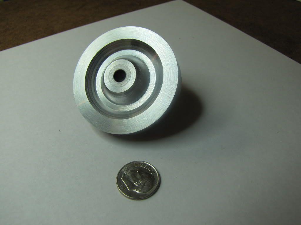
As you suspected Vernon...rim, dish, hub (boss)...

IMG_0205.jpg


I used the same approach as on the sides of the cylinder. Plunged a little then cut to the tapers. The question was...how do I know where the edges of the rims/hub/boss are? I didn't think they were critical. I'd very much like to know what others would have done. What I did was dykem the face and scribe where the edges were. Then carefully cut to the edges. After just a couple of passes, the edge helps keep you true. You can even tell by the sound of the tool when it comes up to the edge.

The drawing called for 30 degree angles to the dish. I don't have a cutter for that. I tried the thread tool...but that was pretty much of a disaster as most of you would have known without trying. I had a cutter with near 80 degree (~39 on each side) so I tried that. Set the cross slide at an angle to get the same angle on either side and to ensure the tool holder wouldn't hit the chuck. 30 degree, 38 degree...I thought it would be okay so long as the dish had sufficient valley to look okay. I think it does.

Now needs the hole in the boss for the set screw. The instructions call out an angle vise. I don't have one so this might be another adventure.

Then it's sanding and polishing. For the rim I thought I could mount the flywheel on the crankshaft or something similar and have the lathe chuck hold the crankshaft. Then the rim is completely clear and can be sanded in one go without having to flip. Speeds are low and not much force so should be okay.
 
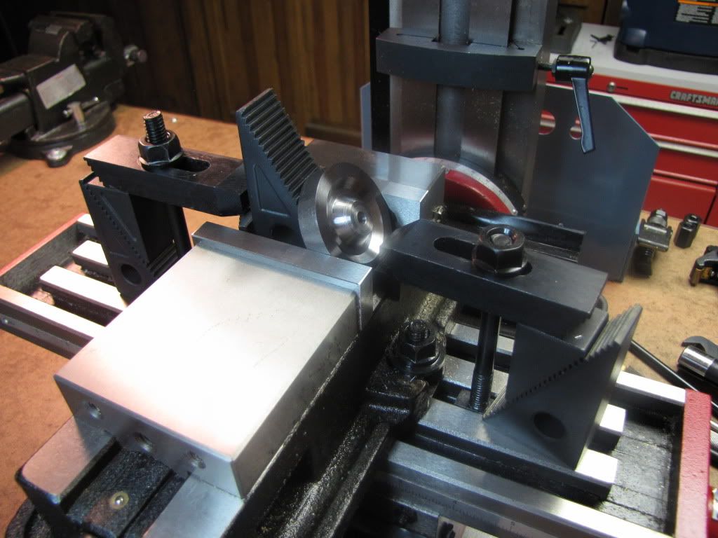
A hole needs to be drilled into the boss 60 degrees to the bore.

I have no angle vise.

I have memories of Marv telling me to be careful of objects 'squirting out'.

The saw-toothed blocks (what do you call those) from the mill's clamping kit form a 30/60 angle. Hm...

What do you think...
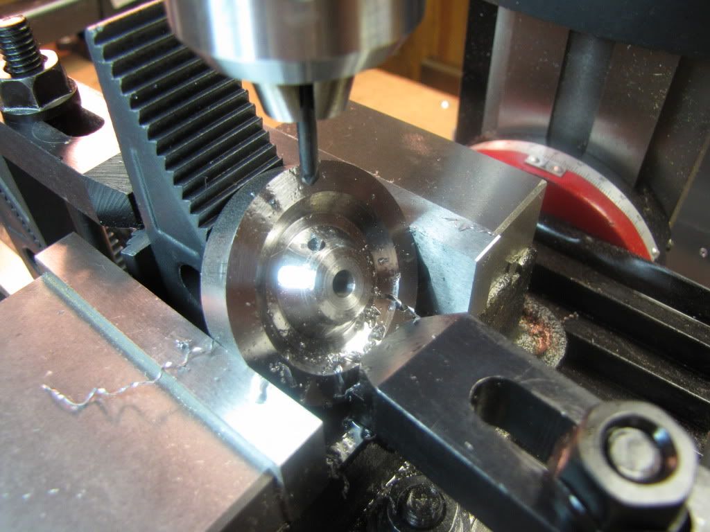
IMG_0206.jpg


I used the same approach as on the sides of the cylinder. Plunged a little then cut to the tapers. The question was...how do I know where the edges of the rims/hub/boss are?

Keep forgetting how to format the "here" into links
http://www.homemodelenginemachinist.com/index.php?topic=844.0

shows a method for flywheel recesses. It is a tad on the noisy side.

Smooth finish on facing, speed and feed. I don't have a powered cross slide so cobbled a hack to do that. Slow 2.5 rpm motor that turns the cross slide. Its such a fine feed that the surface is baby bottom smooth. Takes a good 20 minutes to face a 4 inch piece

http://www.homemodelenginemachinist.com/index.php?topic=2086.0

Some ideas on the subject
 
zeeprogrammer said:
A hole needs to be drilled into the boss 60 degrees to the bore.

I have no angle vise.

I have memories of Marv telling me to be careful of objects 'squirting out'.

The saw-toothed blocks (what do you call those) from the mill's clamping kit form a 30/60 angle. Hm...

What do you think...
Step Blocks i think. Not that i know anything but a piece or two of an old soda can as chaffing material will help reduce the "Vise marks" on your flywheel. After you drill that hole tap it then and there using the same setup to keep the tap straight.

Double shot of tequila should the tap break :)
 
Carl,
Looks solid enough but be careful when the drill breaks through at an angle. The drill can break through on one side and pull itself into the hole like a coarse screw breaking the bit. DAMHIK
Dave
 
Zee: I am really enjoying your building series posts. I had to learn what little I know by myself and find that I am learning a lot by following your thread. All your questions and all the answers are giving me a lot of hints on how I can do a better job when I am in my shop----Thank You---- for being willing to take the time and effort to ask the questions and show how you did several setups and why some were better than others.
Kudos to you for a very good build series.
don
 
Robert...thanks for the links...I'll take a look soon. Right now I'm recovering...you'll see why soon. Didn't get to the tap yet so I don't need the tequila remedy. But a remedy will be needed and it will contain some of the same ingredients.

I had wondered about the marks on the back. The idea of a soda can cushion is a good one. I'll remember that.

Dave...are you a fortune teller on the side? Or did you hear the dim scream coming from eastern PA and knew what happened? Stay tuned...

don...thank you very much. If people are enjoying this...and especially if it helps them...then it's very worthwhile. (Someday it will give me an excuse to show off. But it's not today...)

So here we go...

Supposed to use the wiggler and disc point to find the center of the part. But that was with an angle vise in the +/-x direction. Further, the edges of the part are rounded and you would have to move +/-z to ensure you find the outer most edge.

In my setup, the direction is +/-y and the outer most edge of the part is near or under the vise top.

So instead…I’ll use the edge finder and the inner sides of the vise jaw.

Then, supposed to use the wiggler and needle point to find the edge of the boss (hub).

Then move in 0.13 inch, center drill, drill, spot face, and tap 8-32.

However, the 0.13 inch assumes a 30 degree angle. I cut at ~38 degrees (or is it 52?). I doubt the difference is very significant…but lesson here is to first understand the consequences of any changes I make.

Cedge’s thread on ‘Getting Centered and Edgey’ was a big help in learning to use the wiggler. Thanks.

Almost had a disaster…using Marv’s equation for determining the drill size needed, I calculated ~0.153. Way different than the chart’s 0.136. When I plugged in the chart’s numbers, the DOT was ~118%. Huh? It turns out the chart had the wrong major diameter. 0.184 instead of 0.164. Then I got a DOT of 70%. The chart is in The Home Machinist’s Handbook. Yet another reason not believe what you read/hear…always check. Should check Marv too.

Center drilled.
Drilled.
Screamed.

That was no 'dink' like when the #56 broke. This was a 'snap' followed by 'wha?' followed by 'nooooooooo!'. I'm sure you heard it. You had to hear it. A neighbor called (kidding).

IMG_0207.jpg


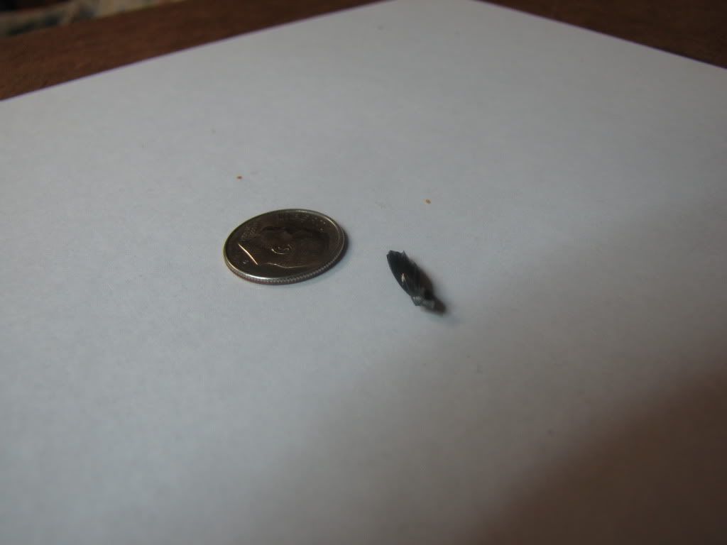
WEAR GLASSES! This is what flew by...

IMG_0209.jpg


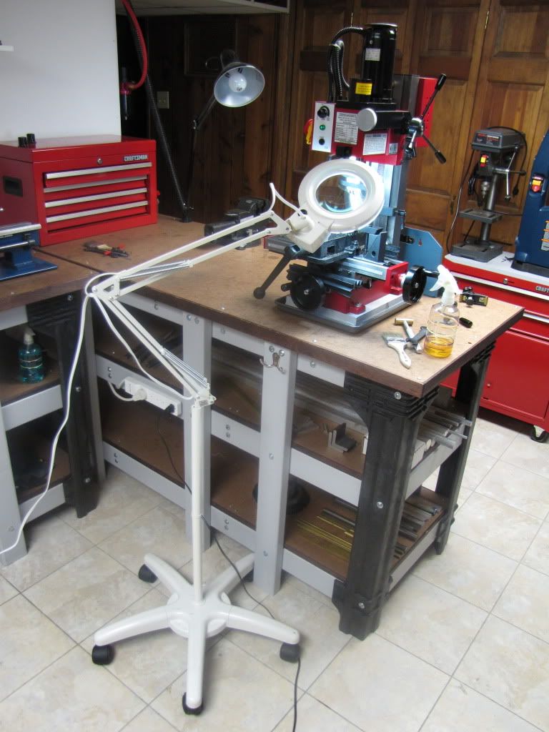
I have a floor lamp with a magnifying glass...

IMG_0208.jpg


Even then I wear glasses.

Normally the other lamp is on too. It's off for the pic. Also, the black cord you see on the floor isn't normally there. It's powering the camera.

BUT GOOD NEWS!!! I got the broken bit out! A little push from the hole and a pull from above with pliers.

THE BAD NEWS!!! No drill bit.

THE GOOD NEWS!!! Just yesterday I discovered a hardware store nearby that sells numbered drills.

Thanks everyone for making this such fun.


zeeprogrammer said:
I don't need the tequila remedy.

Drum Roll

Center drilled.
Drilled.
Screamed.

Tequila Time.

A piece of close fitting stock down the flywheel shaft hole, dab of loctite or other to keep it from moving will help reduce the bits tendency to "pull" when breaking through.

Bit stuck in hole = Double Shot
Bit removed from hole = Double Shot

Love simple rules :)
 
Foozer said:
A piece of close fitting stock down the flywheel shaft hole, dab of loctite or other to keep it from moving will help reduce the bits tendency to "pull" when breaking through.

Sounds good.

Any chance the stock would get stuck? Not from the loctite but from material from the part your drilling through?

Any chance the stock would gouge the hole when it's removed?

I agree with the rules...or rather...rule. Just not the tequila. But to each their own. ;D
 

Latest posts

Back
Top