Model Carburetor Design Query

Home Model Engine Machinist Forum

Help Support Home Model Engine Machinist Forum:

This site may earn a commission from merchant affiliate links, including eBay, Amazon, and others.

cfellows

Well-Known Member
Project of the Month Winner
Joined
Aug 25, 2007
Messages
3,890
Reaction score
715
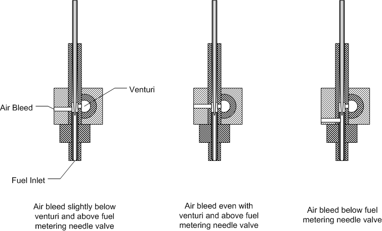
Below are drawings of my latest carburetor design showing the air bleed in 3 different positions:
FellowsCarburetor_zpse311ad09.png


I'm assuming there would be little difference between 1 and 2 where, in both cases, the air bleed enters the carburetor above the fuel metering needle valve. However, I'm wondering about the 3rd case where the air bleed enters the fuel stream before the fuel metering needle valve.

Anybody have any thoughts about any of these three positions?

Chuck
 
Chuck, it looks to me like putting the air bleed below the fuel metering needle and orifice will cause the mixer to suck air instead of fuel through the needle valve and orifice which would make it difficult for the engine to draw fuel from the tank.

I don't think the engine would know the difference between the first two designs.

These are my thoughts. Trying the three options on your engine will tell us for sure.

Interesting project.

Regards,

Chuck Kuhn
 
Hi Chuck,
I'll try not to make this too long winded. In automotive carbs there are what they call air bleed holes. These are in fact ported into the fuel supply channels but for a slightly different purpose, to prevent the fuel from siphoning through the passages once there is no vacuum signal. They do add a small bit of air to the fuel flow. Motorcycle carbs have and air passage which might be called an emulsifier. It is an air cavity ported into the fuel passage which in fact helps break up the fuel droplets. When you consider the size of our carburetor and the amount of fuel they flow I don't know how a person could accurately calculate what size air bleed would be needed.
Now the air bleed (airplane type) carbs that a lot of us use is a little different animal. When the throttle barrel is wide open the main jet needle is adjusted for optimum performance. When the throttle barrel starts to close the venturi effect starts to increase because of the reduction in the air passage. This in turn creates a greater vacuum and starts to pull more fuel. When the barrel is at the idle position the vacuum signal is at it's greatest and the engine is running (if at all) way too rich. To overcome this condition the air bleed hole is ported into the throttle barrel hole (which is now almost 90 degrees to the carb bore. By doing this the vacuum signal is reduced and therefore the fuel flow. The air bleed port is adjusted by a screw that's threaded across this passage. When the engine is idling the air bleed screw will lean out the mixture to where it's about 15:1 (We hope). When the engine is idling if the air bleed port is wide open and the engine is still rich then the port size needs to be increased. If the throttle is returned to the idle position and the engine stalls (too lean) then the air bleed screw needs to be closed up a little.
gbritnell
 
George wrote an excellent reply, to the surprise of no one. :cool:

Hi Chuck,
I'll try not to make this too long winded. In automotive carbs there are what they call air bleed holes. These are in fact ported into the fuel supply channels but for a slightly different purpose, to prevent the fuel from siphoning through the passages once there is no vacuum signal. They do add a small bit of air to the fuel flow. Motorcycle carbs have and air passage which might be called an emulsifier.
Air bleeds do perform both functions in full size practice. Additionally, there are three basic circuits, idle, mid-range, and main, and the air bleeds are used to "time", or balance out the transitions just like changing mixture needles and fuel jets.
It is an air cavity ported into the fuel passage which in fact helps break up the fuel droplets. When you consider the size of our carburetor and the amount of fuel they flow I don't know how a person could accurately calculate what size air bleed would be needed.
I think this is one of those parts where we get screwed by the scale. We need microbubbles at scale and I believe the hydrogen bonds in the fuel will prevent that.
Now the air bleed (airplane type) carbs that a lot of us use is a little different animal. When the throttle barrel is wide open the main jet needle is adjusted for optimum performance. When the throttle barrel starts to close the venturi effect starts to increase because of the reduction in the air passage. This in turn creates a greater vacuum and starts to pull more fuel. When the barrel is at the idle position the vacuum signal is at it's greatest and the engine is running (if at all) way too rich. To overcome this condition the air bleed hole is ported into the throttle barrel hole (which is now almost 90 degrees to the carb bore. By doing this the vacuum signal is reduced and therefore the fuel flow. The air bleed port is adjusted by a screw that's threaded across this passage. When the engine is idling the air bleed screw will lean out the mixture to where it's about 15:1 (We hope). When the engine is idling if the air bleed port is wide open and the engine is still rich then the port size needs to be increased. If the throttle is returned to the idle position and the engine stalls (too lean) then the air bleed screw needs to be closed up a little.
gbritnell
Chuck, as to which of your three designs are most suited to your purpose, I suspect only testing will tell. Fuel has mass and thus momentum, but instead of having a full float bowl right next door to use, waiting to spill over, we have to use the entire venturi signal to pull it through tiny fuel lines from a tank way over yonder. That wastes a good deal of energy, which you might not want to give up to an air bleed.
 
Last edited:
With extra air in the fuel will give better atomizing under full load, unuseful in idling in model engine and need the extra fuel system for idling.

In car carburator has all 5 system:

1. Float system (used in older gas engine)
2. Choke system (rare used in model engine)
3. Idling system (Rare used in model engine, Gas engines with walbro carburator to example has idling system)
4. Main system (most used in all model engines as spraybar)
5. Acceleration system (used in Webra dynamix carburator in Webra model engine)
 
Thanks George, Jeff, Jen, for the excellent discussion. Lots of different model engines out there and many different requirements.

I have been trying to design a carburetor that is simple to build, that will allow the engine to idle slowly without misfiring, and will throttle up to a moderate speed with no additional needle valve adjustment.

I've just about decided that the air bleed on my design is unnecessary. With the air bleed hole closed off, I can adjust the needle valve to a point where the engine will idle around 300 RPM, albeit a little rich on the mixture but doesn't misfire, and will throttle up nicely without any further adjustment of the mixer.

By the way, I am able to adjust the air bleed aperture by twisting the fuel jet assembly slightly which causes the hole in the jet to misalign with the hole in the body.

Chuck
 
This concept might be worth trying. fThis is a simple design that works well on the small Norvel RC engines. The barrel translates a bit on the thread when it rotates. The needle is opposite the fuel fitting and slightly reduces the orifice area. A combination of thread pitch and needle taper makes this work.

norvel carb.jpg
 
To make word easy: The barrel is full open with needle far away from the spraybar in full load, then rotate the barrel sideways affected by treads or the angled groove on the barrel where the pinscrew is mounted on carburator body would lead the barrel sideway and the main needle is moving into the spaybar and the fuel is reduced to a correct fuel/air mix in idling.

Read this link http://www.rc-airplane-advisor.com/model-airplane-engine-tuning.html
 
Back
Top