LONGBOY'S "BLACK WATER" MODEL GAS ENGINE.

Home Model Engine Machinist Forum

Help Support Home Model Engine Machinist Forum:

This site may earn a commission from merchant affiliate links, including eBay, Amazon, and others.

Longboy

Well-Known Member
Project of the Month Winner
HMEM Supporting Member
Joined
Nov 19, 2009
Messages
841
Reaction score
598
Location
Tucson, AZ
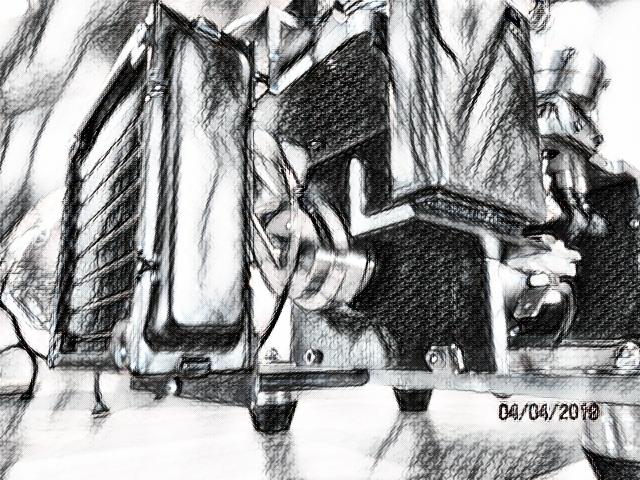
Trying out a sideline as a plumber with my first liquid cooled model. More parts and more area needed on the frame for those parts, Black Water turned out to scale with these external additions. Don't think I will return to L.C. soon..... but gave me a chance to try out another cooling option for my industrial type engines. BLACK WATER starts this week with an abbreviated build log!
xDr0aSS.jpg
 

Attachments

  • 155751090290509048.jpg
    155751090290509048.jpg
    91 KB
Last edited:
Not sure of how much water jacket I would need, the area between the outer wall of cylinder liner and inside wall of the water jacket. That was determined by bringing home some 2in. galvanized water pipe and using my DOM stock for a 1.25in. bore. Gave me about .312in. fluid area around the cylinder. Looks good.
IMG_2832.JPG

Aluminum end caps bored for the liner clamp the jacket. Grooved recess with RTV and a pair of socket head #6 screws seals up the perimeter wall.
IMG_2833.JPG
 
Will you machine water pump or just simple siphon cooling.
You wrote // Don't think I will return to L.C. soon....// is this engine your last one?
 
Will you machine water pump or just simple siphon cooling.
You wrote // Don't think I will return to L.C. soon....// is this engine your last one?

Not my last engine, just not thrilled with the involvement on water cooling types from bar stock. There is a circulation pump on BLACK WATER.
 
The cylinder drops in.
IMG_2834 (1).JPG

The gap in the bottom cap takes the epoxy to lock the cylinder with the cap. two 4-40 socket heads hold the assembly to the deck. On the top side cap, there is no adhesive.
IMG_2837 (1).JPG

The cylinder head bolts to the top cap and the o-ring is the water and combustion seal then.
IMG_2836.JPG

The socket heads that draw the end caps to the water jacket are not sealed under the cyl. head to provide fill overflow or steam relief. There are no water passageways in the heads.
IMG_2809.JPG
 
Going to need a water pump. I made this vane pump using a block of Delrin. It is a mag drive unit. I also bought an electric gear pump as a choice too.
IMG_2841.JPG

This tested out pretty good running on the lathe with a water flow loop. The magnets didn't start to slip till after 2500 RPM. Good enough for an engine that idles away. The vane drum is 1 inch dia. and the cavity in the block is 1.25 inch.
IMG_2842.JPG

The issue is it's size in scale to BLACK WATER. Even after trimming off the block to a square, I was going to have packaging issues in mounting.
IMG_2843 (1).JPG

Save for the next liquid cooled engine I may never build, the exercise was worth doing and can be used as an accessory driven by any engine to pump water to show work.
IMG_2844.JPG

The electric gets a spot on BLACK WATER.
 
Last edited:
The crankshaft has a 2 bearing support with a dummy web between the rods. That segment is 3 piece, steel rounds bridged with aluminum tube. This was changed out as my crank webs were slipping on the throw pins and at fast idle or just starting a reluctant engine put the flywheel into a wobble.
IMG_2840.JPG

That piece was near 12 oz. and the distance between the bearings and the web load on the throw pin too great, being my longest twin cyl engine. BLACK WATER should be a 3 bearing engine. Lets see if I can lighten the load on the throw and get by on 2 bearings. Third bearing always an option.....
IMG_3336.JPG

A couple of rolls of electrical tape.........just kidding. :p A pair of aluminum dummy webs weigh 5 oz. total on the throw pin. The set screws with adhesive hold everything nice now. I took another 3 oz. outta the flywheel and dished the pistons for a lower compression for ease of starting. With the engine running, the throw pin disappears in a blur and it looks like nothing supporting the crank between the con rods then.
 
Center punch a good way to locate an idler gear for the timing set.
IMG_2848.JPG

If I get "slightly" off, the shaft for the idler can be drilled a few thousands eccentric off center and then pivoted on its bolt to achieve equal gear lash, drive to driven.
IMG_2955.JPG

The lobes for the cam on BLACK WATER are unique, something I've haven't seen this material used for. Made from half inch dia. Delrin, they are easier than metal to cut & file on the profile. Low heat on the camshaft as well as low spring pressure and no need to lube, I think they will last well on slow RPM gas engines. They make a distinctive "clickety-clack" against the lifters you can hear on startup and running in the video!
 
Engine finished minus its cooling system and initial start-up with the fruit jar vapor induction. At this point not running or running poorly for seconds. Crankshaft issues the main culprit. Continue with the cooling system from here.
IMG_3139.JPG

IMG_3140.JPG

The light weight webs on the throw pin from previous posting still not enough to overcome the distance between bearings to keep the ends of the crankshaft straight and parallel. A center bearing will be going in now.
IMG_3359.JPG
 
Hi/low flow fittings in side of the jackets. Aluminum blocks for the gravity return flow to radiator and some basic 5/32 in. brass tubing with home grown #10-32 fittings fed by the pump. I managed to get the tubing to bend this short radius without collapsing.
IMG_3150.JPG

A 2 inch dia. fan pulls through the radiator and bracketing on radiator to mount to the deck of BLACK WATER.
IMG_3145.JPG

IMG_3146.JPG
 
The fan on the nose of the crankshaft turning 1200 RPM is not going to move too much air. Giving it some help with a shroud.
IMG_3147.JPG

A slice off a 16 oz. acrylic tumbler from the dollar store going to work here.
IMG_3148.JPG

It will help some.
IMG_3149.JPG

And mounted to the engine.
IMG_3306.JPG
 
The water pump active using a 6V penlight battery pak. This was a fall back option as I didn't have a can motor driven as generator by belt drive with enough omph to get the pump running. Not sure at this point if pump needs to run constant or periodically or if hot water affects its lifespan in demonstrations.

IMG_3364.JPG


The Delrin fill manifold on top of deck has a nipple under red cap to load the coolant. Same level as top of jacket.
IMG_3365.JPG
.
.
This concludes the build log of BLACK WATER.
Coming-Soon.png

155751090290509048 (1).jpg


:).......LIKE THIS WEEKEND! DAVE
 
WELCOME TO LONGBOY'S "BLACK WATER NOW" PRESENTATION! :)
IMG_3151.JPG

1.25IN. BORE/ 1.125IN. STROKE--------45CC'S.
IMG_3152.JPG

WORK BEGAN ON BLACK WATER WEEK BEFORE CHRISTMAS.
IMG_3166.JPG

AND COMPLETED END OF APRIL.
IMG_3157.JPG

MY LARGEST TWIN ENGINE BY OVERALL SIZE.
WEIGHT: 14 LBS.
IMG_3169.JPG

FEATURING PLASTIC CAMSHAFT LOBES. (DELRIN)
IMG_3168.JPG

AND WATER COOLING.


ENJOY! DAVE.


Attachments

  • IMG_3163.JPG
    IMG_3163.JPG
    113.8 KB
  • IMG_3165.JPG
    IMG_3165.JPG
    109.8 KB
  • IMG_3176.JPG
    IMG_3176.JPG
    124 KB
Longboy,
That little mag-drive water pump that you built looks like an interesting project in itself and it might be just the thing to connect to a small engine when showing off how it runs. I find with any engines (I've got some old hit-'n-miss engines) I always get the question: "What does it do?" The bigger engines at shows are sometimes shown with a pump or feed grinder operating. This would be great to set up a display with a miniature engine.
Could you possibly post some tips or hints for building one?
 
The vane pump in post #7 is made of Delrin and the mechanics are straight forward. Here is a 1.187 in. bore cavity swept by a 1 in. drum with four brass vanes. The drum is offset to its chamber and the vanes are the chamber seal on the close contact drum to chamber and the sweep medium up in the open volume chamber area between intake in output ports. The aluminum cap separates the driven internal drum and the external drive pulley. A shaft through the cap is the axle for the pulley and is offset to match the vane drum. The drive pulley has a pair of roller bearings. A brass shaft through the pump body supports vane drum. Brass on Delrin as a bearing.

IMG_3644.JPG
IMG_3645.JPG
IMG_3646.JPG
IMG_3647.JPG
IMG_3648.JPG
IMG_3649.JPG
IMG_3650.JPG
IMG_3651.JPG
IMG_3652.JPG
 
Thank you for your reply, but .......

You are obviously at a skill level beyond me (I checked your YouTube videos and those engines are amazing quality) and I don't mean to hijack this thread but this nice little miniature pump fascinates me. I recognize the magnetic drive idea to allow for a well sealed pump unit.

I understand the "driven" portion of this pump but what drives it? I don't mean the magnetic portion. I understand how that works and I understand the operation of the rotor. What I don't understand is the "driving element" with the large center bore that appears to be mounted solidly to the aluminum cap. You mentioned the pulley with the roller bearings and I don't see this. Could I ask you to please elaborate just a bit more?
 
Sure! The drive pulley is incomplete and is shown as a piece of round stock Delrin without a belt drive groove machined in. The bearings are in this piece and it rotates upon the aluminum cap held on with a 6-32 screw through the roller bearings. Nor is there any mounting brackets or holes drilled through the pump body for mounting to the engine frame. Since I was not using this pump, I left these items unfinished.
I recommend the use the largest diameter and length of neo-magnets no matter the size capacity of the pump you build. The drag of its vanes against the coolant will cause slippage of the magnets at faster engine speeds. Not really an issue with hit /miss engines or conventional gas engines closer to near idle rpm's. Belt drive pulley ratio diameters can vary to flow needs to higher rpm applications with mag drive pumps also.
 
Last edited:

Latest posts

Back
Top