Jacobs Ladder---

Home Model Engine Machinist Forum

Help Support Home Model Engine Machinist Forum:

This site may earn a commission from merchant affiliate links, including eBay, Amazon, and others.
Wife's home, supper is et, Jeapardy is coming on.
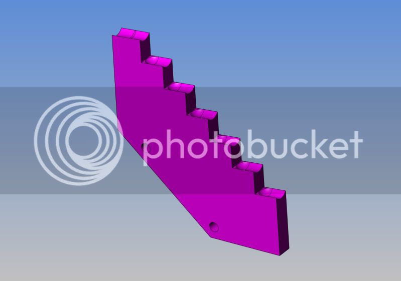
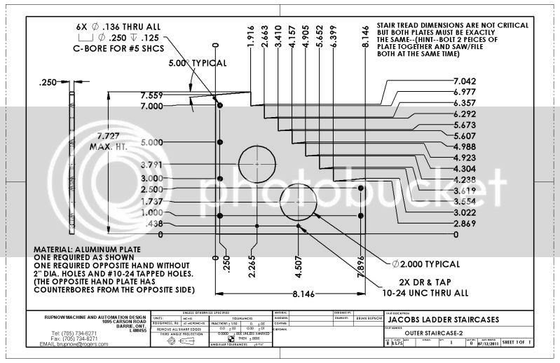
OUTERSTAIRCASE-2.jpg
 
This is a really cool mechanism Brian!

or should I say, "What is, A Cool Mechanism!" ;)

I am curious to know how you are going to machine acute angles on the stairs?

Kel
 
Kel--I thought of that myself----Thats why, in the upper right hand corner of the drawing, I make reference to "non critical" and "saw/filing". I don't really know of any other way myself. However, as long as both sets of outer stairs are identical, it won't be a real problem. There is plenty of "play" in the way this thing will work. I have my software drawing template set to 3 decimal places---This assumes that whoever has enough moxy to attempt making something like this will know which dimensions must be held to a high accuracy and which can be "close" and still function. For me to do it any other way creates too much hassle when creating the drawings. In a real world "work" situation, where accuracy costs $$$$ I would take the time to change the number of decimal places and implied accuracy.
 
Thanks Brian. I scrolled the image and now I see the note. ;D

I know what you mean about tolerance being expensive. My new job, which I love BTW, has me reading prints much like I did when building engines, except for the dimension tolerance. I now know what .63 is supposed to be :big:

Kel
 
Alexandre that music you suggested is perfect (rush is my favorite band) some good canadian music for a good canadian gizzmo :big:

what do you think brian ?

chuck
 
No need to machine an acute angle for the stairs, an ordinary end mill, cutting at 90° will work fine provided the stairs are oriented at a slight tilt (5°?) from the vertical and horizontal plane - ie once your square edges are established, lean the workpiece into the cutter.
 
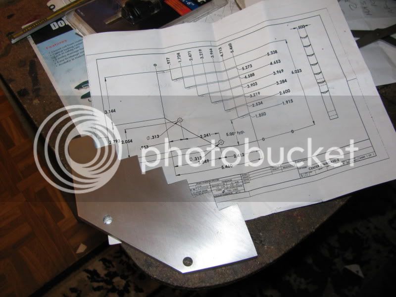
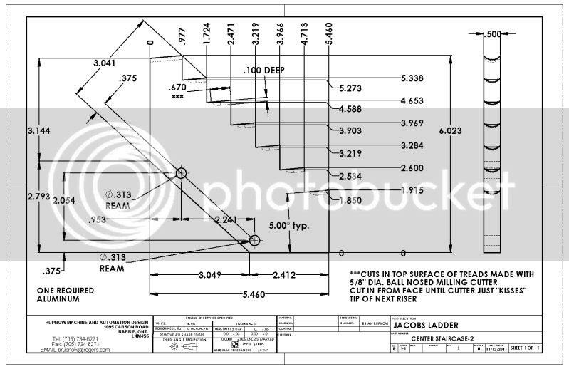
Tonight I was going to post a drawing of the center section of stairs, but on closer examination I decided there is no way to build what I had designed, at least without going to a lot of grief. So---tomorrow I will experiment with the 5/8" dia ball nosed cutter I bought while building the popcorn engine, and depending on what results I get, will post a drawing "after the fact".
CENTERSTAIRCASE-2.jpg
 
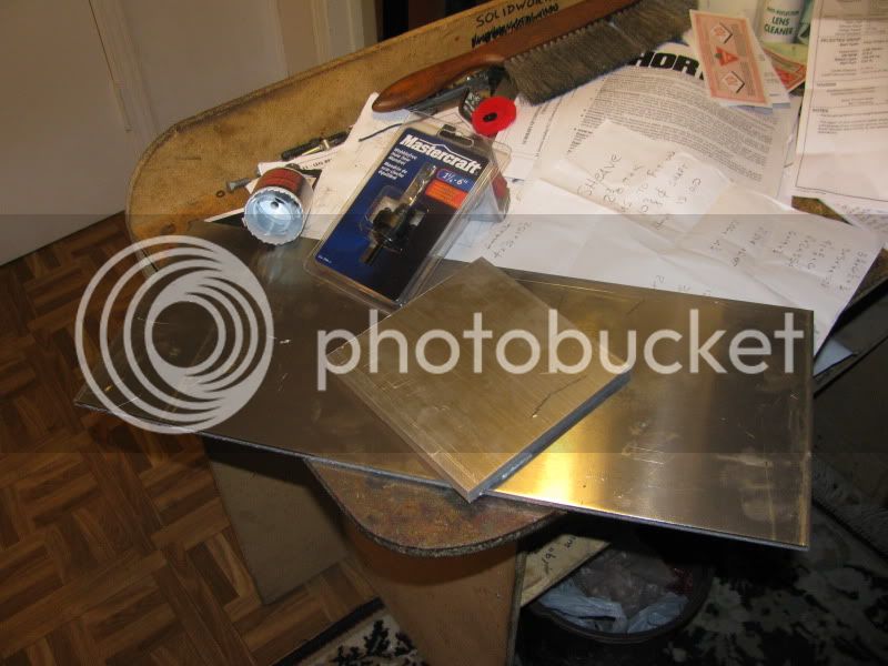
Let the games begin!!!! Went down to my favourite metal supplier and got all the plate to make the Jacobs Ladder for $5.00. thought I was really smart, so went up to Canadian tire and bought a 2" bi-metal hole saw and an arbor for it. All the money I gained on the price of aluminum was soon lost at canadian Tire-----the holesaw cost $18.99 and the friggin' arbor cost $28.99. Oh well, what the heck, I'm working every day, earning real money.
MATERIALFORJACOBSLADDER001.jpg
 
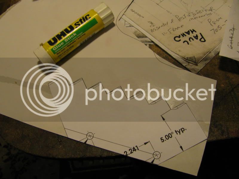
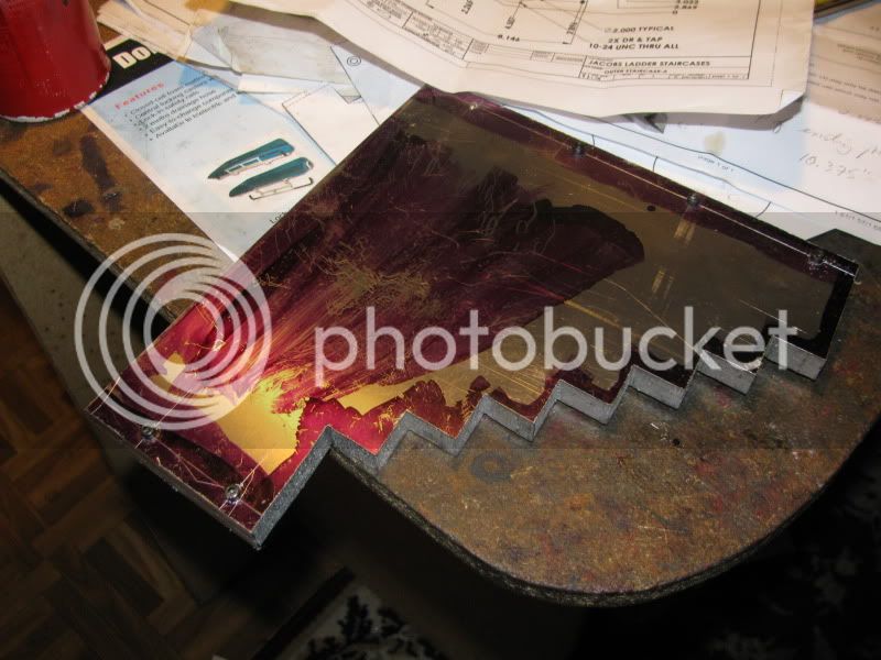
First step--Print out center staircase at 1:1 scale, cut it out, glue it to poster cardboard. I don't usually recomend doing this, but on a part where the only two critical things are the hole centers, it is perfectly acceptable.
papertemplate001.jpg
 
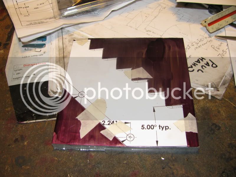
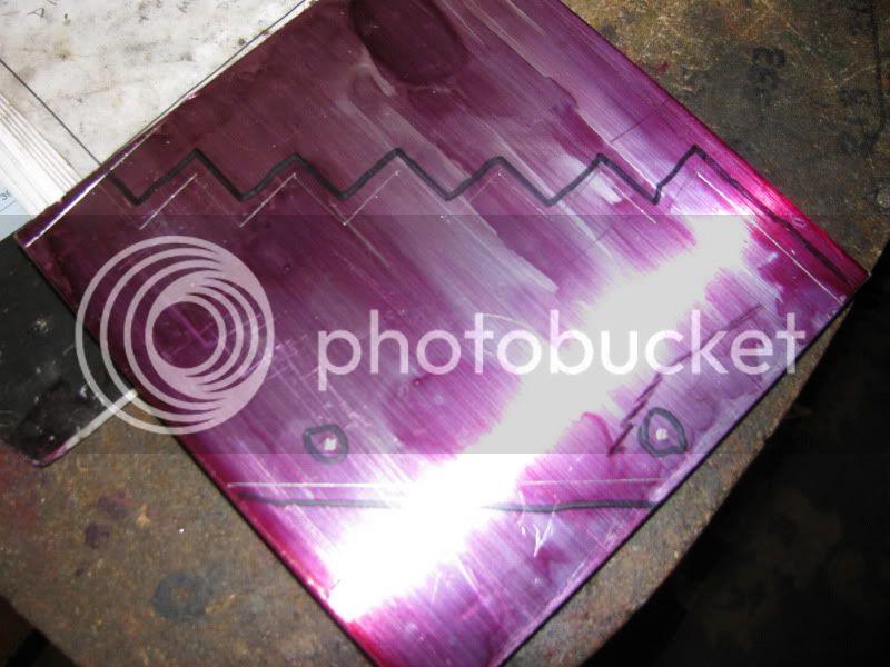
Cut out cardboard, tape it firmly to the peice of aluminum to be cut, which has been coated with Dykem, and scribe around it. if the pattern has two "square" edges, take time to align them with the edges of the aluminum before taping it in place.
scribedaluminum001.jpg

scribedaluminum002.jpg
 
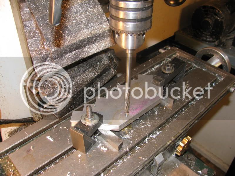
This is one of those times when I absolutely can not afford to have the center axis of the holes to be out of square with the staircase, causing it to "orbit". I don't really trust my "Tilt a whirl" vice, because the moving jaw kicks up a bit when it is tightened. When its critical, as in this case, I clamp the part being drilled to the table with a couple of 1/2" square unground lath tools for stand-offs so as not to drill into the mill table. I am going to use 5/16" shoulder bolts to connect the center staircase to the eliptical arms. This will mean that regardless of what it says in the drawing of the outer staircases, they will both need a pair of 2" diameter holes in them---To clear the rotating eliptical arms on one side and to clear the heads of the shoulder bolts on the other side.
drillingcenterstaircase001.jpg
 
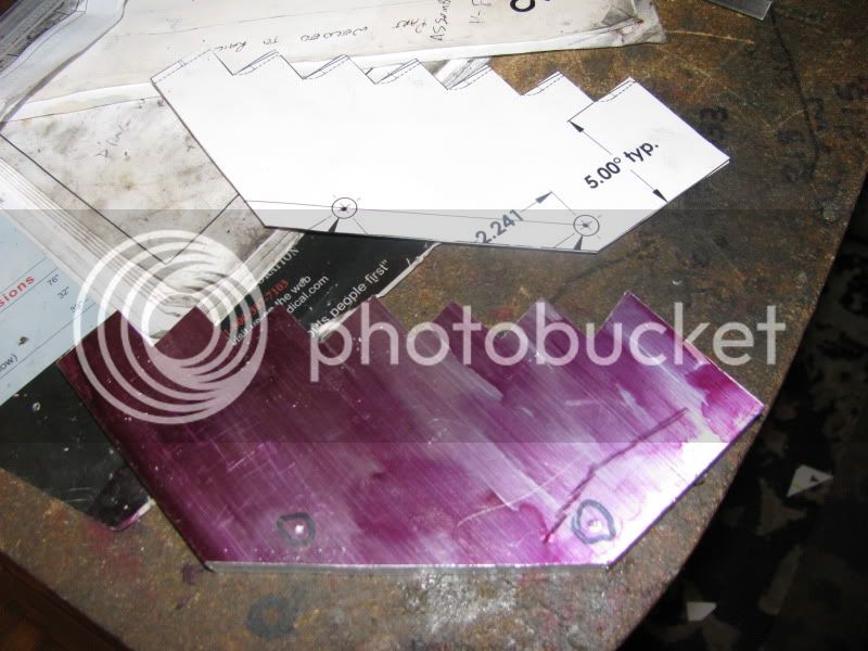
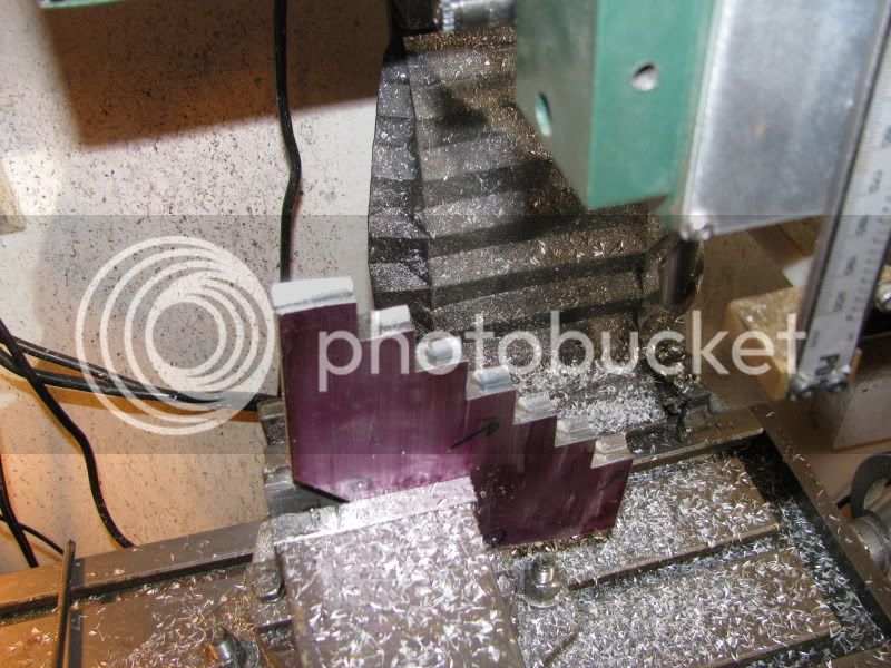
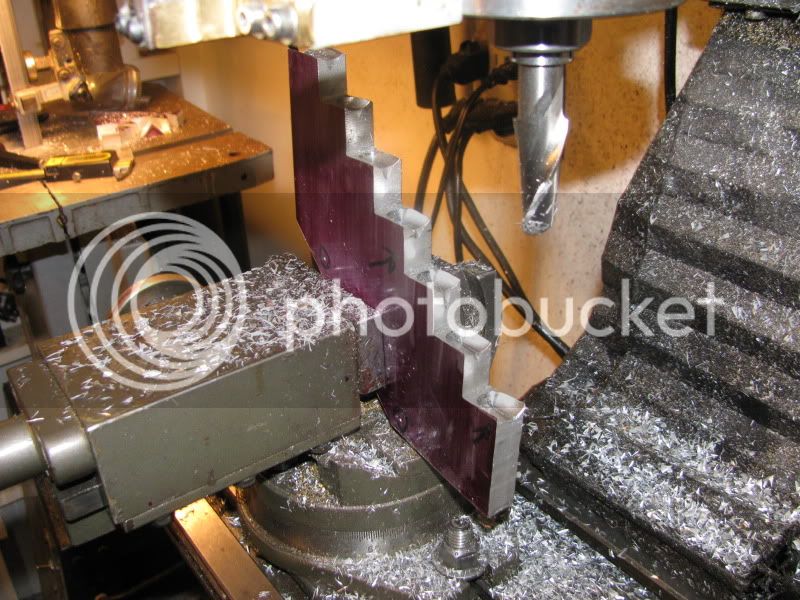
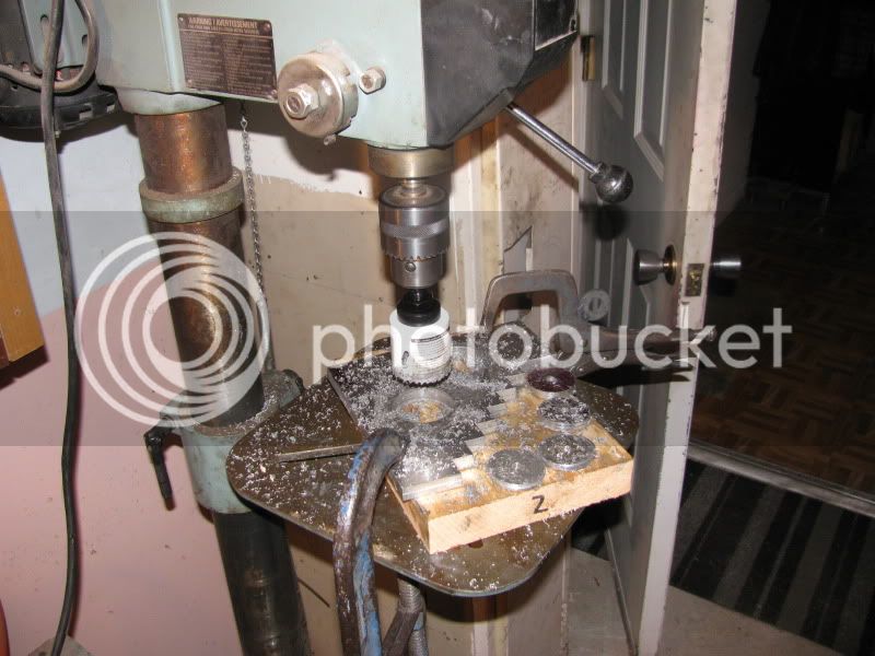
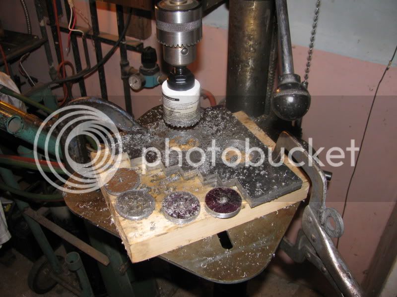
And more of the same---Only this time its the outer staircases. No words of wisdom to offer up here, except that you'll notice I did screw the two peices of plate together BEFORE sawing them out, to keep them exactly the same.
OUTERSTAIRCASESCUTOUT001.jpg
 
Looking good, and moving fast as always. The animation is nice, but I really just can't wait to see it actually go. How about driving this off the krazy klockwork mechanism? ;)
 
The crazy clockwork mechanism ended up being "dedicated".---That is to say, it was attached directly to the base of the popcorn engine and driven by meshing gears. I don't generally do that, as I like to drive my "toys" with a belt drive so that they can be driven by any engine. I MIGHT drive this off the Overcrank Single that appears in my avatar.
 
Well---I'm impressed!!!! The holesaw works great. I did this out on my big old 16 speed drill press in my main garage. The little mill I've got starts popping fuses at anything bigger than a 1/2" drill, and those tiny glassfuses are over $3.00 each. This has been a good days progress.
outerstaircaseholes002.jpg

outerstaircaseholes001.jpg
 

Latest posts

Back
Top