Flat Belt Reversing Mechanism

Home Model Engine Machinist Forum

Help Support Home Model Engine Machinist Forum:

This site may earn a commission from merchant affiliate links, including eBay, Amazon, and others.
One last video before I call it quits. Turn your audio up so you can hear me speaking---I promise it will be funnier!!--Somebody PLEASE let me know if you are able to view the video.--(For some reason I have trouble ensuring that my YouTube videos are set on "public" and not "private".

RhplLS.jpg
 
Great video Brian, it was because of your u tube videos that I joined this group recently. It must be extra effort and time to film and post videos, I really appreciate it, thank you.
 
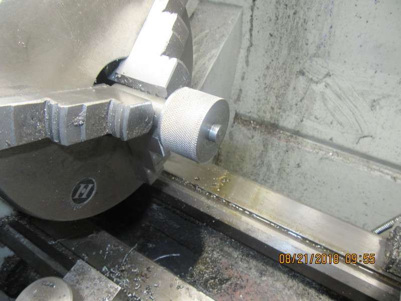
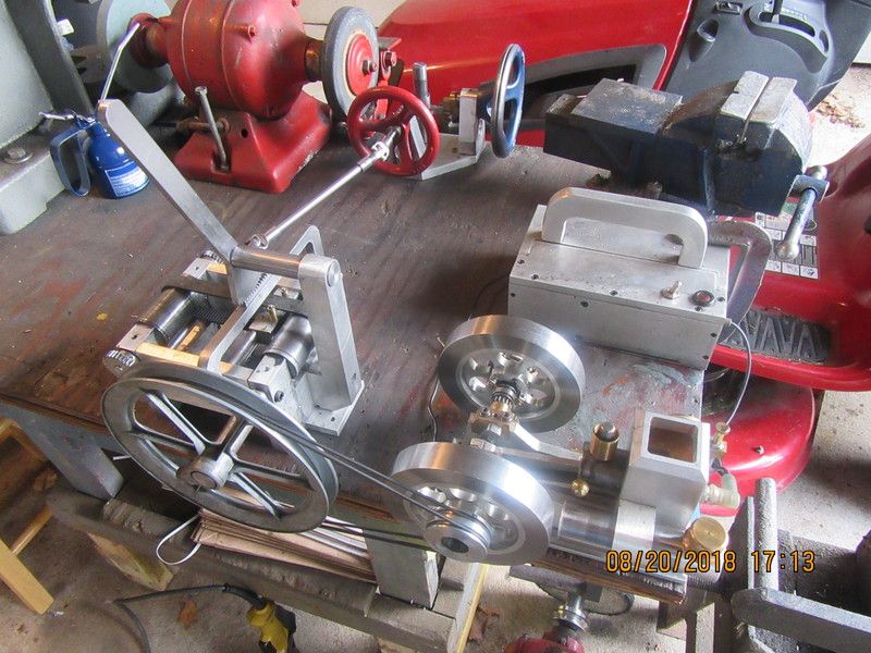
This morning, tired of the belt slipping on the driven pulleys, I removed both pulleys and put a full knurl on the face of each one. I left the center (idler) pulley with a plain face. The head pulley is still smooth. I find that although the set-up is great for demonstrating the fact that I can reverse the output shaft by shifting the belt from side to side, it isn't that great if there is much of a torque load on the output shafts. More experimenting this morning showed that sometimes it could drive the funky corner joint mechanism, and sometimes it wouldn't. The engine wouldn't stall out, but the belt would slip on the head pulley about half the time, unless I grabbed one of the wheels on the funky corner joint and "helped " it to get rolling. I think this is purely a result of the vacuum cleaner belt that I am using as my flat belt. Anyways, this has amused me for a couple of weeks, and we've had a bit of fun with it.---Brian
9H1g79.jpg
 
Last edited:
I don't think the mechanism is nearly as precise or complex as you think. Take a single machine where the motor is on the machine and drives the drum. The drum has two flat belts which can be moved over to one of three positions. One of the belts is crossed over for reverse and drives a 'fast' pulley which is fixed to the shaft. The other belt drives the 'loose' pulley which just spins around on the shaft, sorta like a neutral position. The pulleys are now in 'reverse'. To change to forward, the belts are moved over as a pair. The crossed belt is now on the 'loose' pulley and the uncrossed forward belt now drives the pulley shaft.
The belt is moved via that shifter mechanism. The belts are not tight, and the belts are moved slowly. I'll will dig out some photos of the drive overhead at the local blacksmith museum.
Had
I don't think the mechanism is nearly as precise or complex as you think. Take a single machine where the motor is on the machine and drives the drum. The drum has two flat belts which can be moved over to one of three positions. One of the belts is crossed over for reverse and drives a 'fast' pulley which is fixed to the shaft. The other belt drives the 'loose' pulley which just spins around on the shaft, sorta like a neutral position. The pulleys are now in 'reverse'. To change to forward, the belts are moved over as a pair. The crossed belt is now on the 'loose' pulley and the uncrossed forward belt now drives the pulley shaft.
The belt is moved via that shifter mechanism. The belts are not tight, and the belts are moved slowly. I'll will dig out some photos of the drive overhead at the local blacksmith museum.
Had the same system on chaffcutters.
 
Greg Nixon....In the early 60s the chaffcutters at the feed mill was similar belting. They were about 20 feet long.
 
werowance--I am bored, and that is a dangerous thing. Today I started a new thread about making a muffler for an i.c. engine.---Brian
 

Latest posts

Back
Top