Flat Belt Reversing Mechanism

Home Model Engine Machinist Forum

Help Support Home Model Engine Machinist Forum:

This site may earn a commission from merchant affiliate links, including eBay, Amazon, and others.
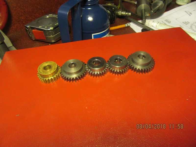
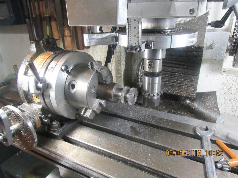
For those of you who get a thrill looking at gears--Here is a shot of the 30 tooth gears just after being cut. I haven't taken them down and parted them off on the lathe yet. And then in the group picture, the four gears I cut today, and one brass gear that was left over from another project and will become my idler gear on this project
UG8hSY.jpg

nXQzjO.jpg

.
 
Thanks for that Brian.
I am nearly up to the stage of having a go at making my own gears and I would like to know if you cut
your gears with one pass. By the the way those gears look neat.

John
 
John--Nice to hear from you. In Australia I assume you will be cutting metric "modular" gears. My gears are "inch" system gears and are #24 diametric pitch. I always cut full depth on each pass in steel or brass. My full depth cut is 0.09" deep. I shelled out about $550 for a complete set of cutters, which will do anything from 12 teeth up to about 108 teeth--that upper limit is determined by the size of my mill, not the cutters. The lower limit is determined by the fact that once you get lower than 12 teeth, you have no room left to bore for a shaft.
 
Thanks Brian.
Yes I have the two modular sets 0.7 and 1 the one being very close to yours. Mine are cheap Chinese cutters from CTC Tools , a little over a hundred bucks a set so I hope
they will cut brass ok....Just because I like the look of brass gears for the contrast .
Cheers
John
 
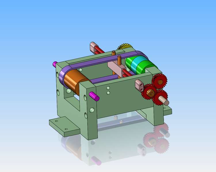
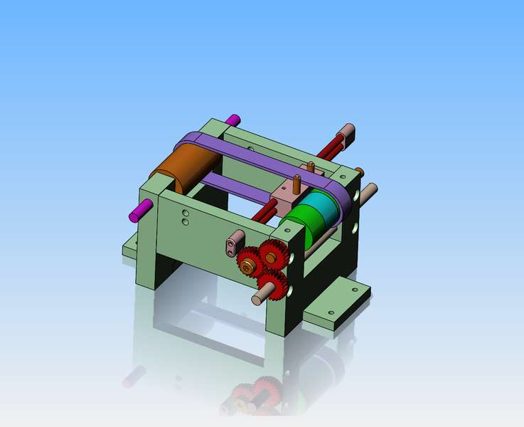
Prompted by J Tiers, I have been doing a lot of thinking on this reversible belt business. I was under the impression that the belt itself stopped and changed direction, and that was my intent with this model, to see if I could replicate this movement. After listening to Jerry's advice and watching a bunch of old sawmill edger and shaping machine videos, the belt doesn't reverse. It is the machinery the driven pulley drives that has the reverse function built into it. The belt always turns the same direction without stopping, but the fact of shifting the belt from side to side and driving the two different pulleys is where the reverse is happening. This doesn't effect the model at all, except the model will be driven from the end with the single wide pulley on it. Now I'm not certain if I need the center "neutral" pulley or not. I will build the mechanism with this center neutral pulley first, because it is already made. Depending on what happens, I may get rid of the center pulley and just have two pulleys at the driven end. It is the countershaft that reverses direction.
 
Once a design has been completed for concept, I have to look at what has to be done to make it practical to build. In my case, this means changing the endplates from 1" thick to 3/4" thick, changing the sideplates to 1/2" thick from 3/4" thick, making the endplates an inch higher to move my pulley centers up an inch higher, and adding "foot plates" so I have a means of bolting this thing down. I have made the changes to the model, and pulled detail drawings off the model, so now I can start to build the frame of this machine.
hsD7MX.jpg
 
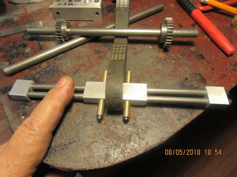
It would have been a lovely day to be at the beach----but I wasn't. Wife was having a lazy day---all my grandchildren were spoken for--So, I worked in my shop. Finished the mechanism which shifts the belt side to side. It looks simple, but there are 11 parts there plus 4 circlips.
vPiQhg.jpg
 
i see what you did with the shifter, the brass are rollers so as to not wear when the belt rubs on them or to drag on the belt when shifting.

I like it.
 
One of the major disadvantages of working at "scale model" level, is that some things simply don't scale down that well and still remain functional. I am finished all of the parts for this project except for the end plates that support the shafts. (I have to buy some material.) My plan is to manually push or pull the shifter to left or right by hand to see how well the belt moves as I slide it from one pulley to another. On a full size rig, I would have a long lever, pivoted at the bottom and a link from the lever to the end of the slider mechanism. The belt can only be moved from side to side while it is running under power between pulleys. I was able to find this animation on YouTube which comes close to what I am trying to do.
 
-I got some more insight into that neutral center pulley. This set-up was used to drive the cable drum on the carriage of sawmills. As soon as a board was cut off by the mainsaw you could go quickly from foreword to reverse to retract the carriage. However, when the carriage got to the load end, the belt was moved onto the neutral pulley so the carriage paused while another log was loaded, or the log being cut could be "dogged over" the width of a board and then the belt was moved from the neutral pulley over to the one which advanced the carriage into the saw.--Belts used on a large line shaft driven shaper didn't need a pause at either end of the stroke, so shapers only had a forward and reverse pulley side by side with no neutral pulley between them.---- Brian
 
Just got home from a great 2 day mini vacation. Wife and I drove over to Peterborough and spent the afternoon telling lies and drinking wine with a good friend I worked with for five years in the zinc die casting business. Him and his wife were great hosts and a good time was had by all.---Now, as to the mechanism--I have thought about the "over center spring loaded toggle" for an automated belt shifting reversing system.. However, I tried that on a different reversing mechanism using gears and a rack this past year, and it failed rather miserably. If the moving parts had enough momentum to let them coast the last bit of stroke, the toggle would have worked fine. However, at small scale and relatively light weight, as soon as the toggle was moved almost to the tipping point, the moving components stopped and just sat there.-Fully disengaging one gear from the rack, but not tipping over far enough to engage the reverse turning gear with the rack. I tried many adjustments and refinements of this system, then decided it wasn't going to work. I will do some thinking on Miners quadrant gear solution, but first I have to buy some material tomorrow and finish the two sideplates and assemble this thing to see it work. Sometimes just seeing a new mechanism work will inspire me with solutions to further progress.
 
I ran a woodmizer sawmill for 25 years, then sold it and assembled and ran an old flat belt driven round blade sawmill from a pile of rusty parts, sold it after 2 years and bought another band mill. The forward/reverse carriage drive was just two flat pulleys on each end with loose belts on both, one flipped over, belt tensioner rollers on a rocker lever tightened one or the other with a forward reverse action of the handle. I used rubber round baler belts, but they tended to warm up and grab, had to use talc powder to keep them slipping properly. leather or woven cotton belts would have been better. I've seen the belts on line shaft equipment set up the same way, with those two sets of belts overhead and a handle hanging down to flip the tensioners onto one or the other, as well as a bar hanging down to flip the main belt back and forth on a stepped pulley to change speed. The simpler it's made the less can go wrong with it. But gear reverse boxes are good for it too. My old line shaft lathe has an aftermarket electric motor on it with reversing switch driving an overhead flat belt pulley, so they eliminated the crossed belt thing. But for some crazy reason I like the old method. Maybe set it back up that way myself someday, being I have a second flat belt lathe now. Although running the shop on steam might be inconvenient, since my usual use of the equipment is a little once in awhile.
 
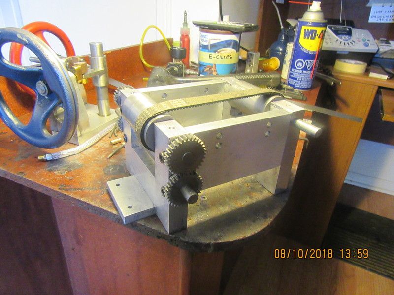
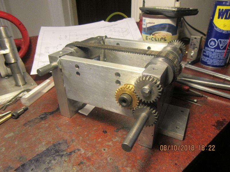
Here we have the first full assembly. I have some serious rework underway with the belt shifting mechanism, and the belt is a little looser than I would have liked, but we are underway.
JtoXxW.jpg
 
Its hard to tell by looking at a 3D model how big or small something is going to be. The shafts on this thing are only 3/8" cold rolled steel. I just finished getting the gear train all sorted out, and it is working as I had intended. Tomorrow I will remake the belt shifter mechanism. I couldn't get the two 1/4" rods which support the belt shifter any closer to the pulley because the idler gear was in the way. Today I decided to go with an offset belt shifter to keep the side guide rollers as close to the pulley drum as I can get them.
m6UX1F.jpg
 
It seems to be a bit of an art to get exactly the right center distance between the pulleys. Built as per my original design, the belt is just a bit too slack, and will slip on the pulleys instead of transmitting power. This picture shows the mechanism with four flat washers 0.055" thick between the one endplate and the sideplates, and this seems to make the belt a bit too tight. I'm starting to feel a bit like Goldilocks. Tomorrow I will try it with some 0.030" spacer washers.
etYziz.jpg
 
Here we have a video of the first "run in" of the flat belt reversing system. I do not have the belt shifter installed yet. This is just a run in for half an hour to take any tight spots or binds out of the mechanism. I have to have everything moving very freely before I reach a final decision on center to center of belt pulleys.--NOTE THAT IN THE VIDEO I TALK ABOUT A 30 MILLIMETER SPACER--SHOULD HAVE SAID 0.030 THOU.-Brian
 
For those of you who are asking about a crown on the pulleys.---The long single pulley, which is being driven by the flat belt in the video will eventually end up as the "driver", not the driven. The belt has to scoot sideways from one end of the pulley to the other when I shift the belt, so it will not have any crown. The two outer pulleys at the other end MAY have a crown if I determine that they need it. The center pulley at the far end may get a crown, or may not. Before I crown any of the pulleys, I have to build the belt shifting device and install it. It is very possible that the belt shifting mechanism will make the belt hold position so that none of the pulleys require crowns.---Brian
 

Latest posts

Back
Top