- Joined
- Dec 5, 2009
- Messages
- 510
- Reaction score
- 47
Hello everyone,
I have a few mechanical model projects I would, like to design and build,
using hydraulics, so this is going to be a experimental project in designing tooling and such, to be able to fabricate micro-miniature double acting hydraulic systems.
Building a single acting cylinder in hydraulics, is easy because there is no need to have a seal at the top of the cylinder, to contain the fluids, as long as the piston to cylinder fitting, is properly done with good compression, and very minute leakage, at the top.
But designing and building a double acting cylinder is more of a challenge, as I need to cap off both the bottom and top, of the cylinder for fluid pressure to push the piston in both directions.
I have decided I want to make a hydraulic system with a 3/8" dia. steel rod, with an internal bore dia. 1/4", so a piston with a dia. 0.249", and a length of 1/4" can be used and the piston rod to be made of 1/8" drill rod.
I looked at the idea of using my follower rest on my lathe, and makeing the piston and rod one piece, however I want the rod to be over 3", and to get a precise turning cut that way for that long of length could run into bending problems, somewhere if not some inconsistant rod diameter.
So I decide it would be best to use 1/8" precision rod, (drill rod) that ensures perfect dia. along the length of the rod. This means now I need to make the piston and rod 2 seperate pieces.
I thought about threading the piston and rod, than assembling together and then machining the piston down to final diameter. Or to press fit a aluminum piston, already to finished diameter, onto the rod.
I decided to go with the press fit method. This means to keep the 1/8" dia. rod from bending, I would need to fabricate a dedicated pressing jig, that I could utilize on my manual press.
I look at a project as being not only the finished work itself, but all the tooling and setups needed to be made in order to build and complete the project.
So building tooling is all part of building the final project itself.
-----------------------------------------------------------------------------------------------------
So here is a run down of what I have done so far, in fabricating a pressing jig:
Since this is a work in progress thread, I will give a lot of detail as possible.
The idea of this design is to press the 1/8" dia. 4" long rod onto a piston, 1/4" dia. x 1'4" long, for
a depth of 1/8".
This jig must support the rod along its entire length, as best as possible, so my design uses a solid rod, and a top plunger, spring loaded.
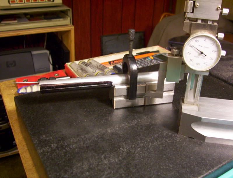
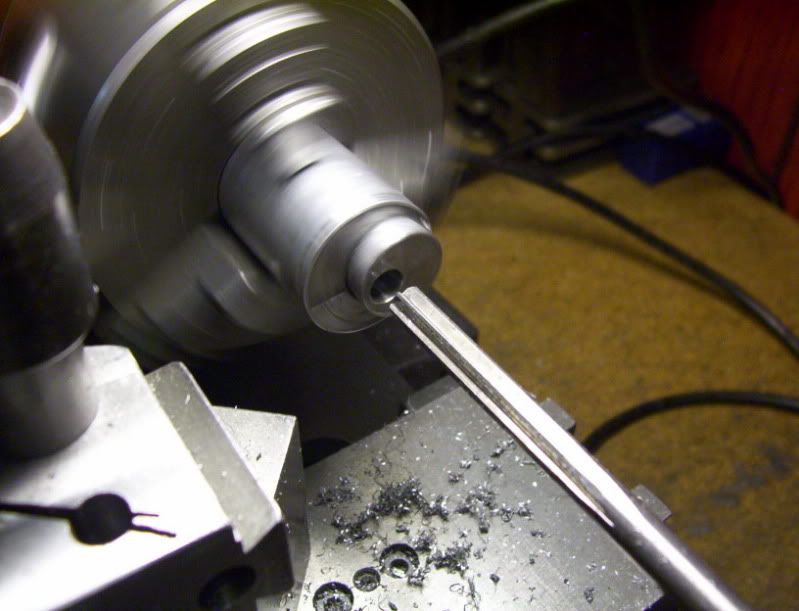
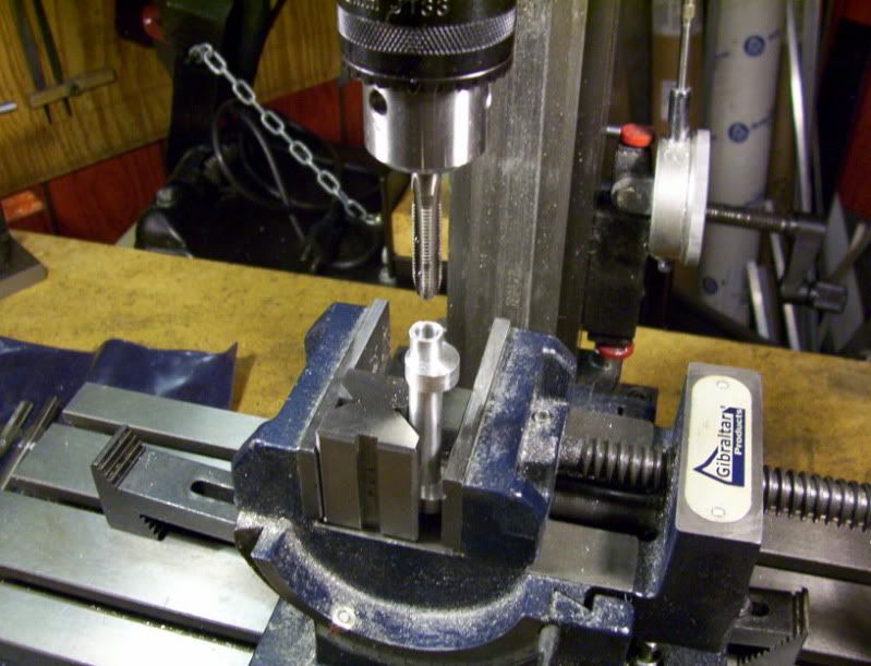
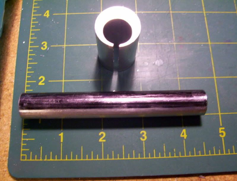
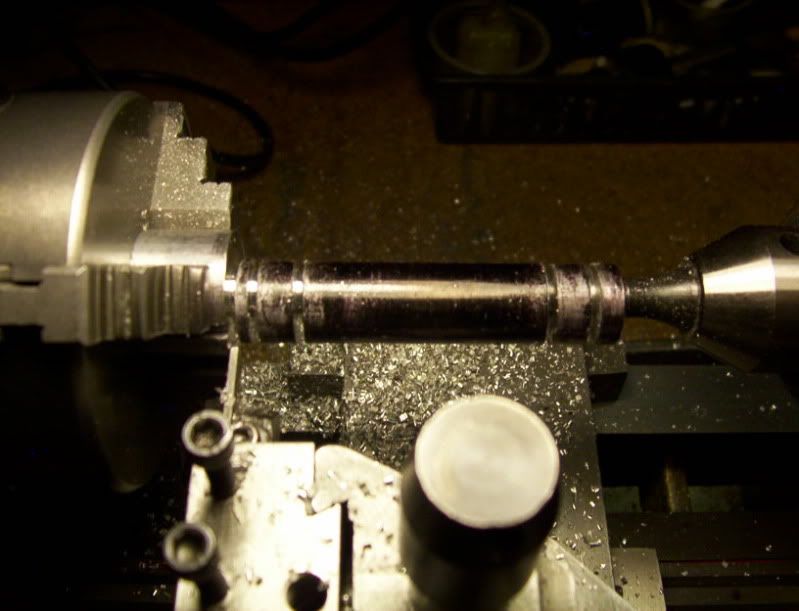
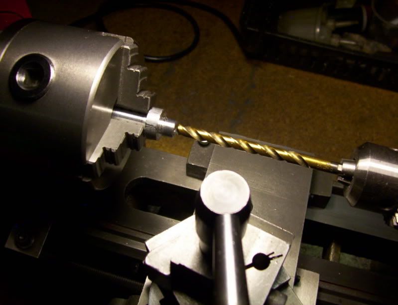
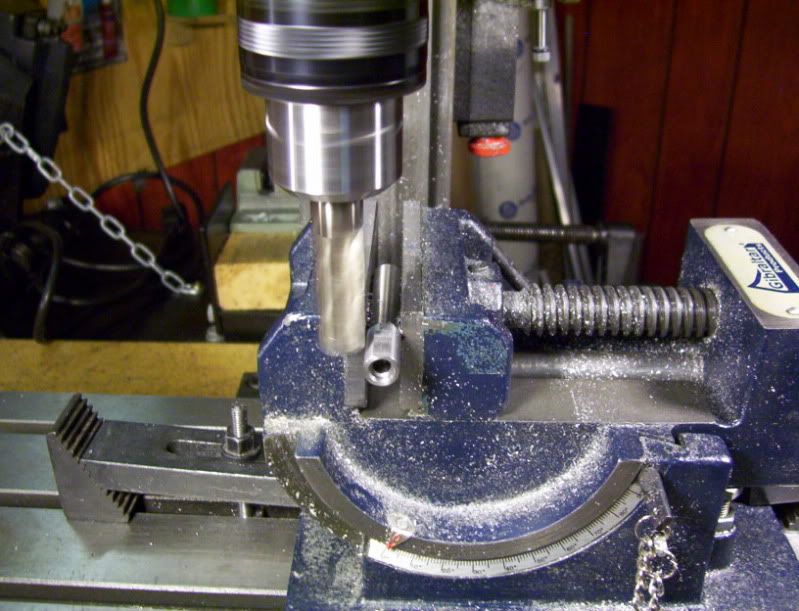
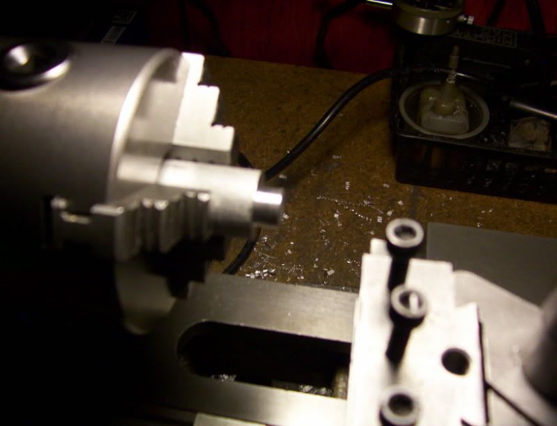
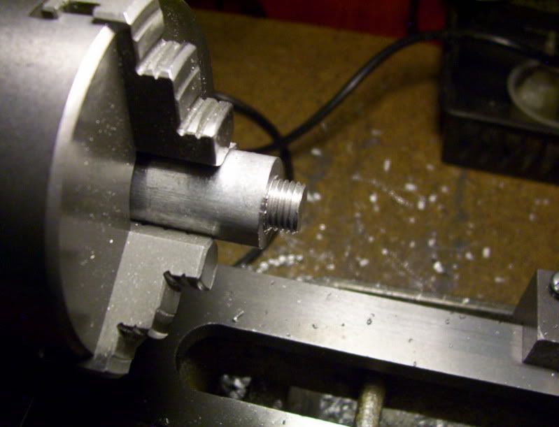
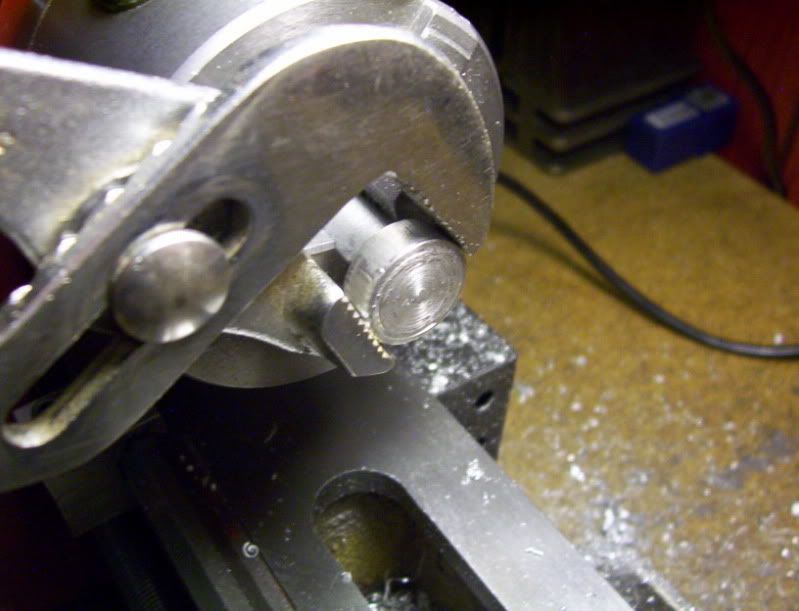
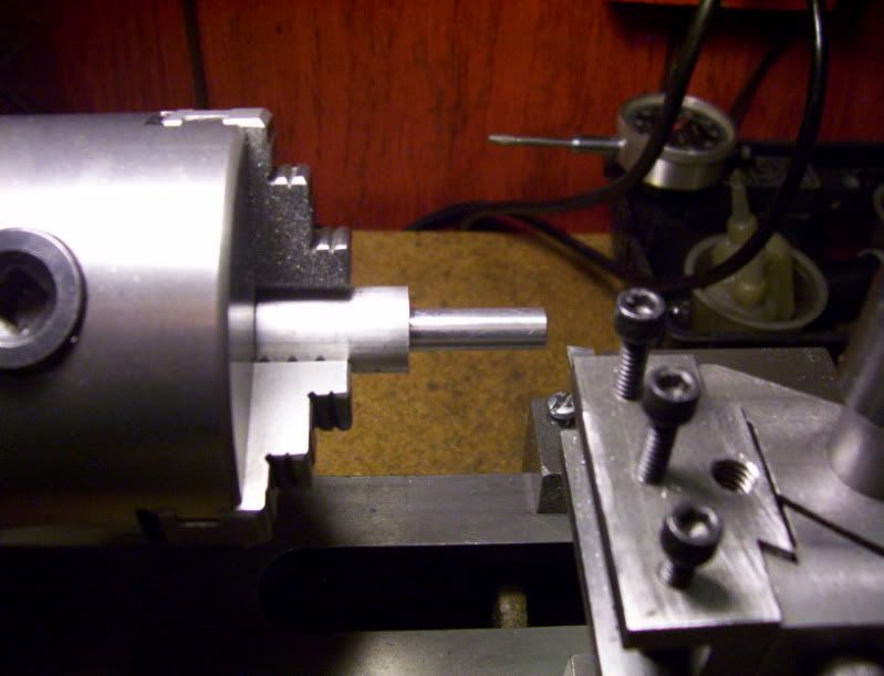
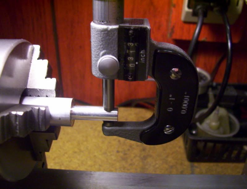
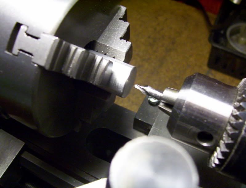
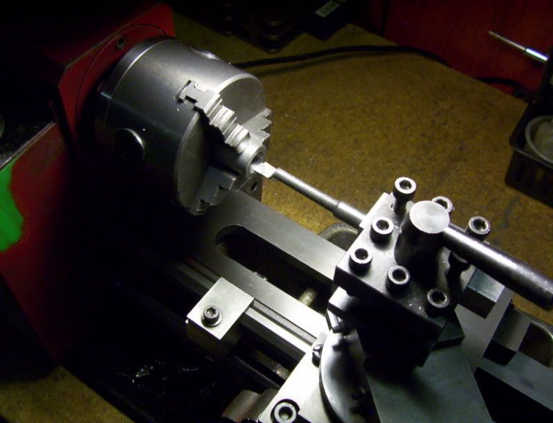
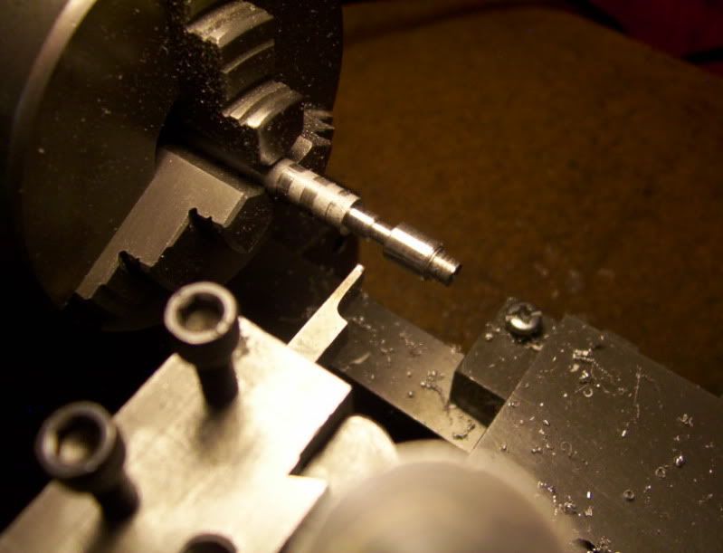
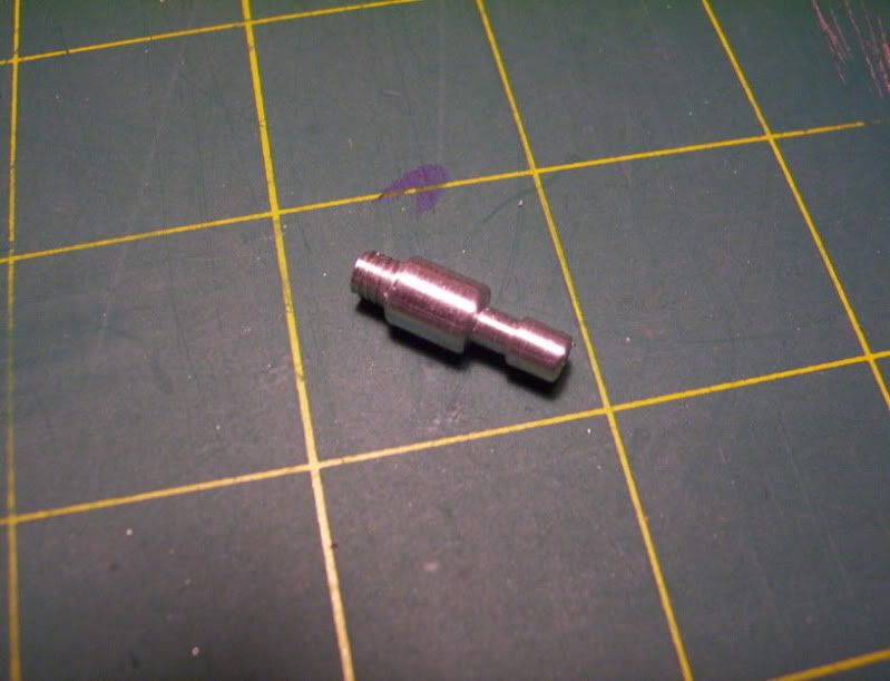
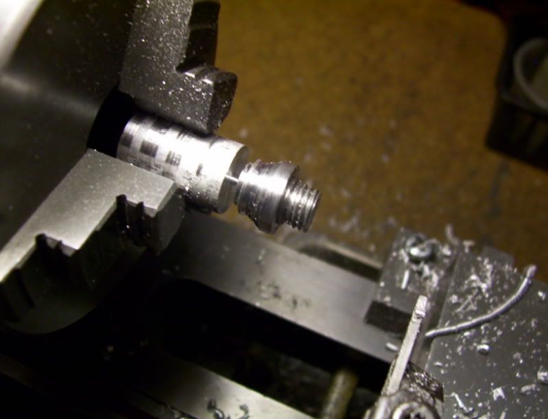
I start out by machining a 5/8"dia. rod to 4" overall length, measuring the length of the spring and its inner dia. shows I need to maching a stem on the end of this rod 5/16" in diameter, for a 1" length.
.
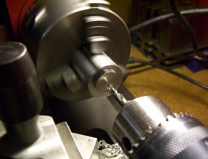
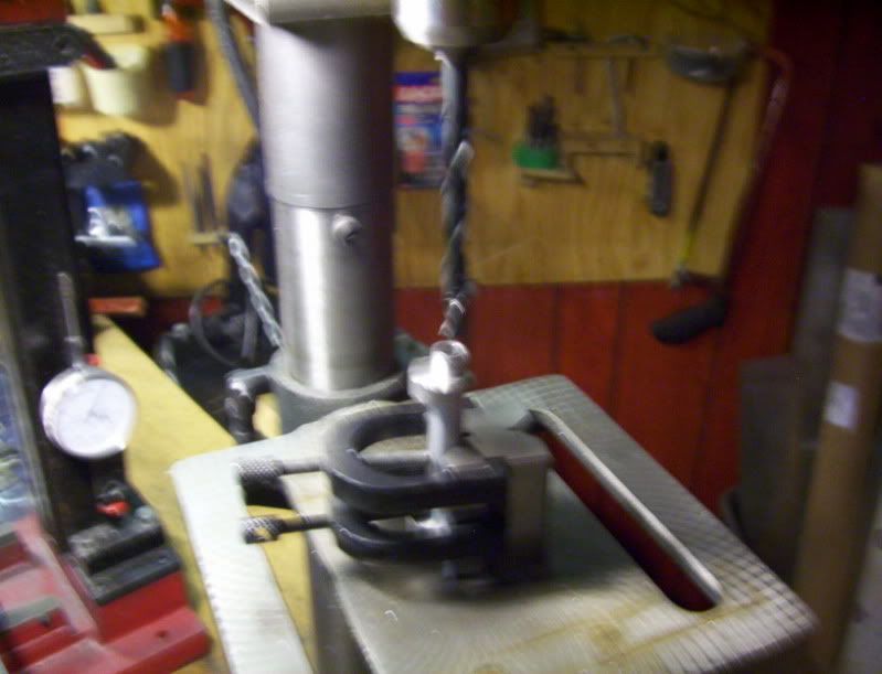
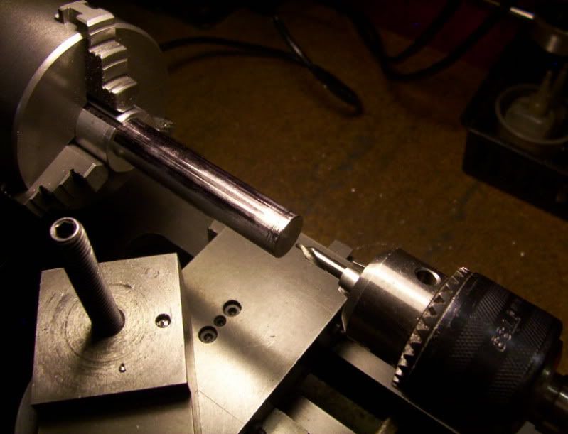
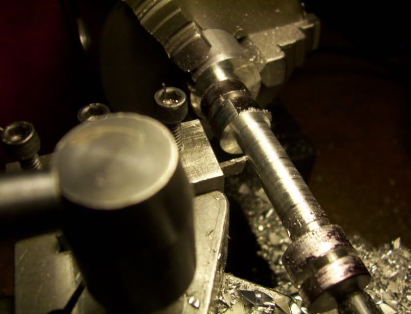
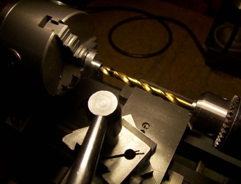
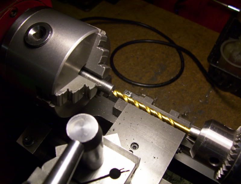
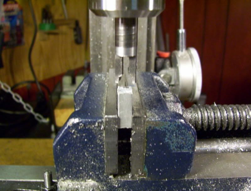
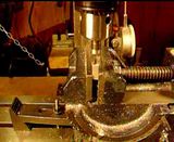
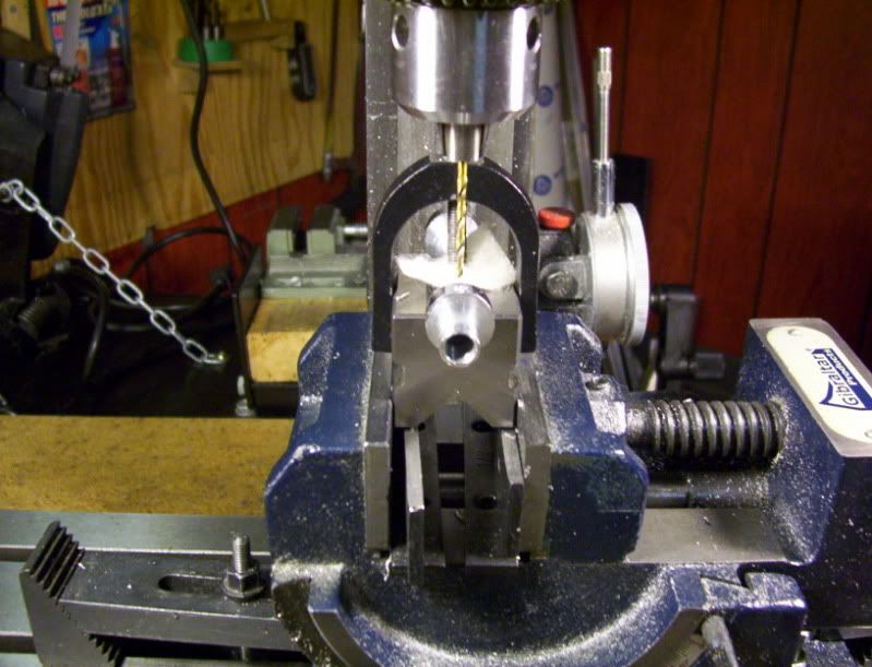
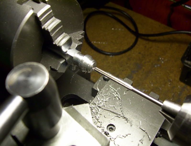
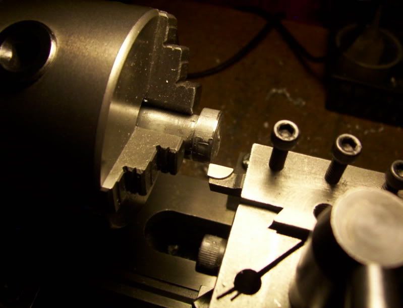
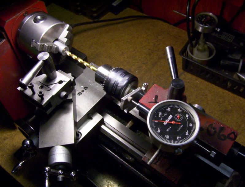
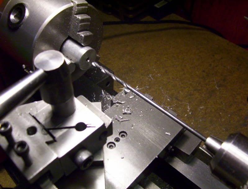
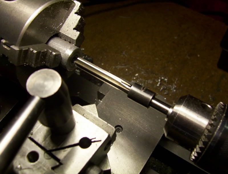
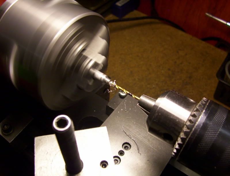
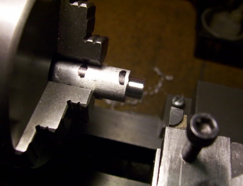
Now to support the 1/8" dia. drill rod its entire length I need to take my time and precisely drill the work piece with a thru hole of 1/8" dia., then finish it with a 0.126" reamer.
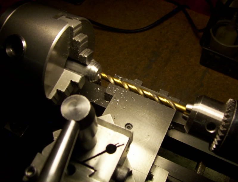
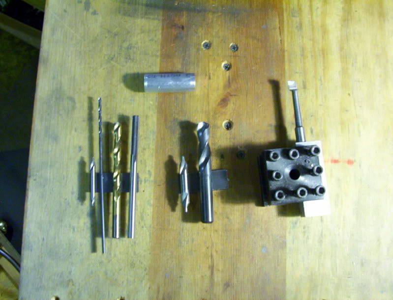
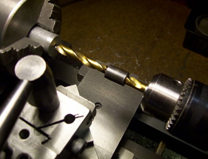
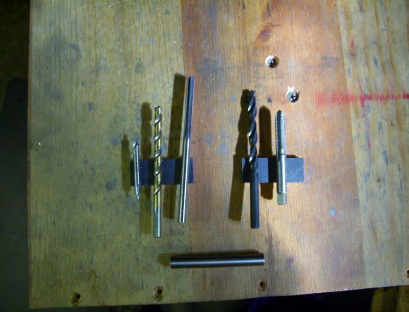
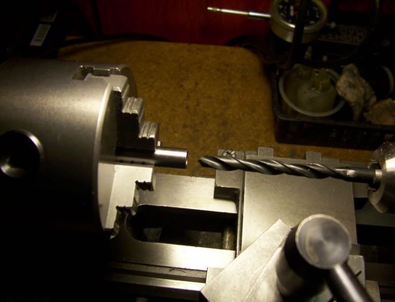
So I need to use my smallest 1/8" screwmachine size drill bit, followed by a 1/8" jobber size, finally following that with my 1/8" aircraft size bit.
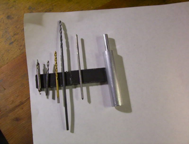
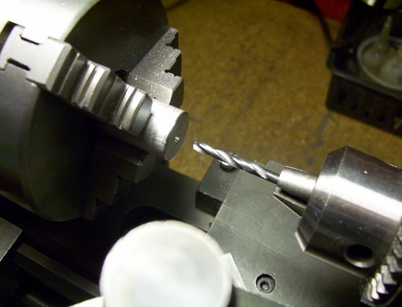
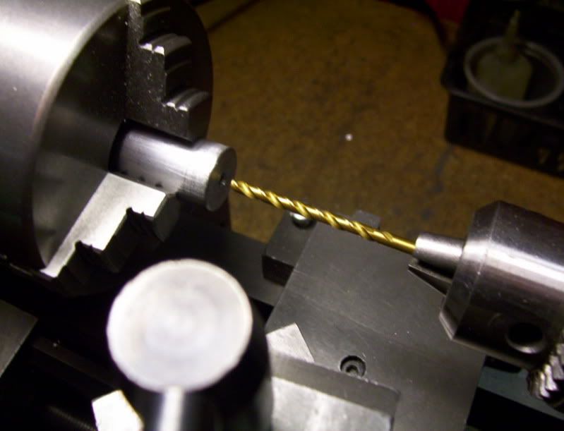
Now I'll ream it with the 0.126" reamer as far as it can go.
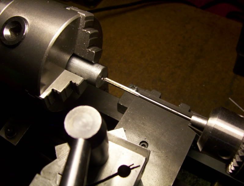
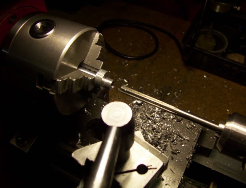
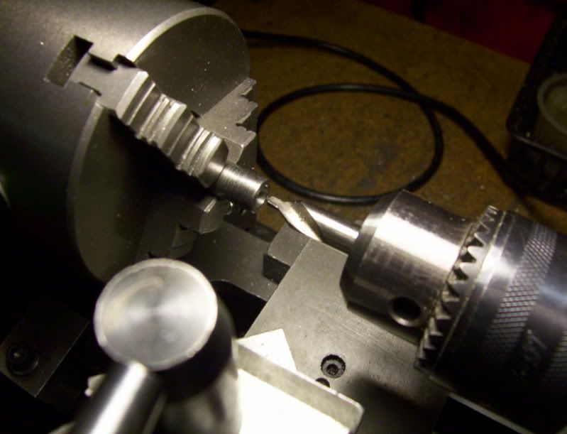
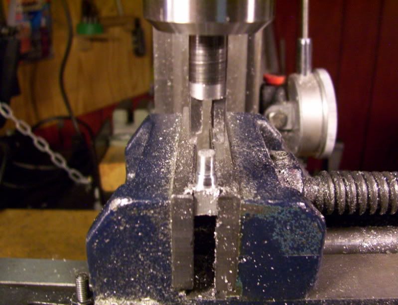
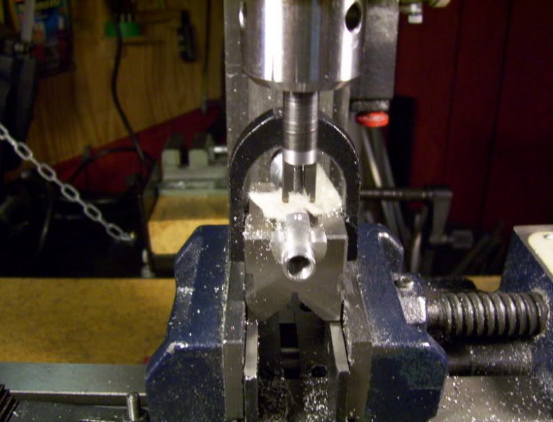
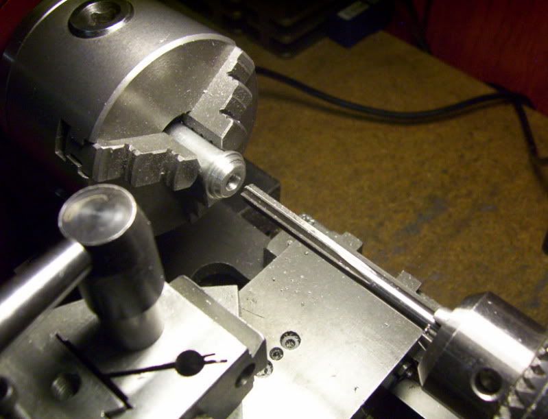
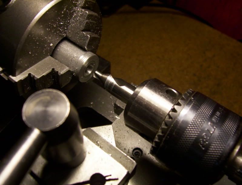
Before I take the workpiece out of the chuick to turn it around to finish thru with the reamer from the other side, I need to drill and ream for a 0.249" hole 1/4" deep at the bottom of the workpiece.
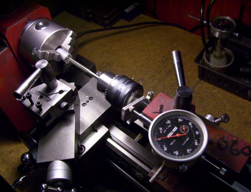
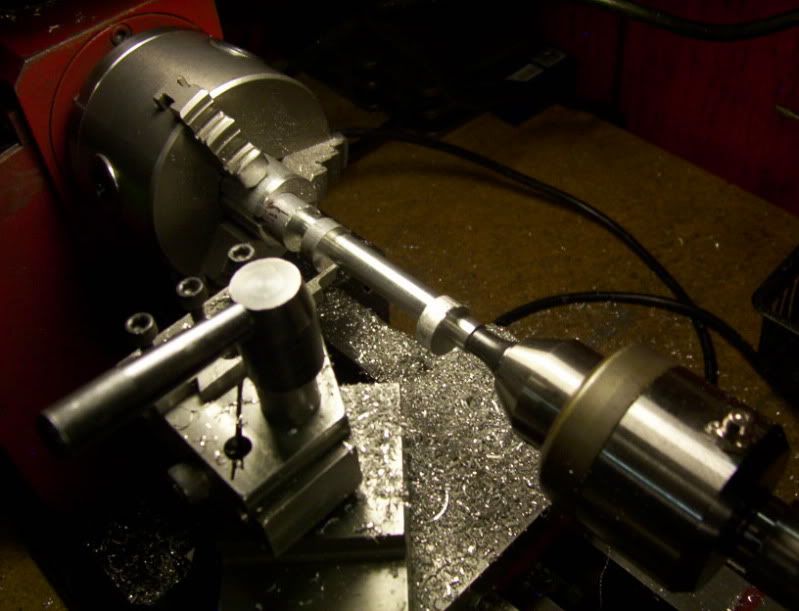
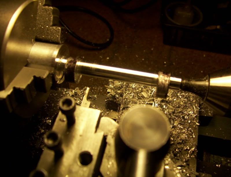
Now I can turn the workpiece end for end to finish the reaming thru the workpiece.
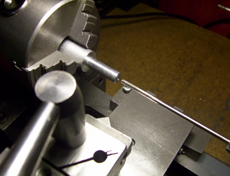
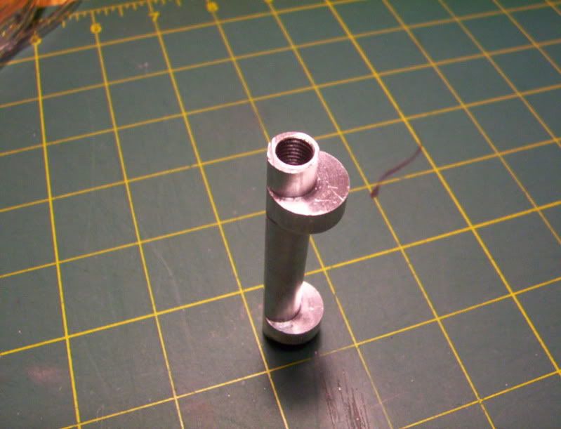
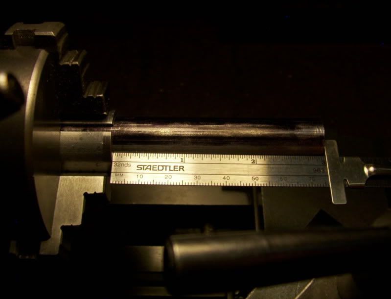
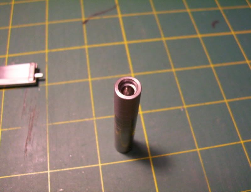
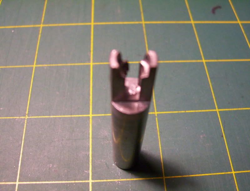
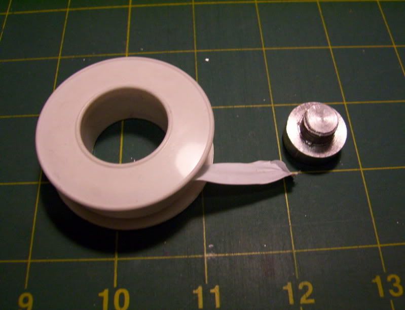
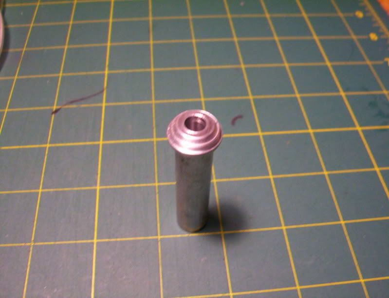
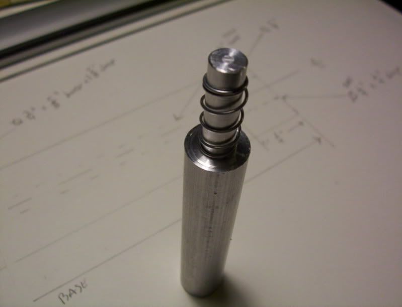
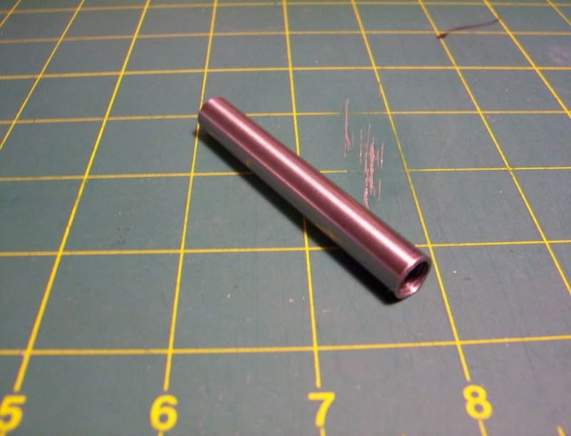
Now here it is with the thru hole as precisely as possible drilled and reamed through, and the spring that will slide on top of it.
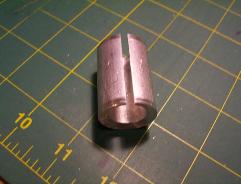
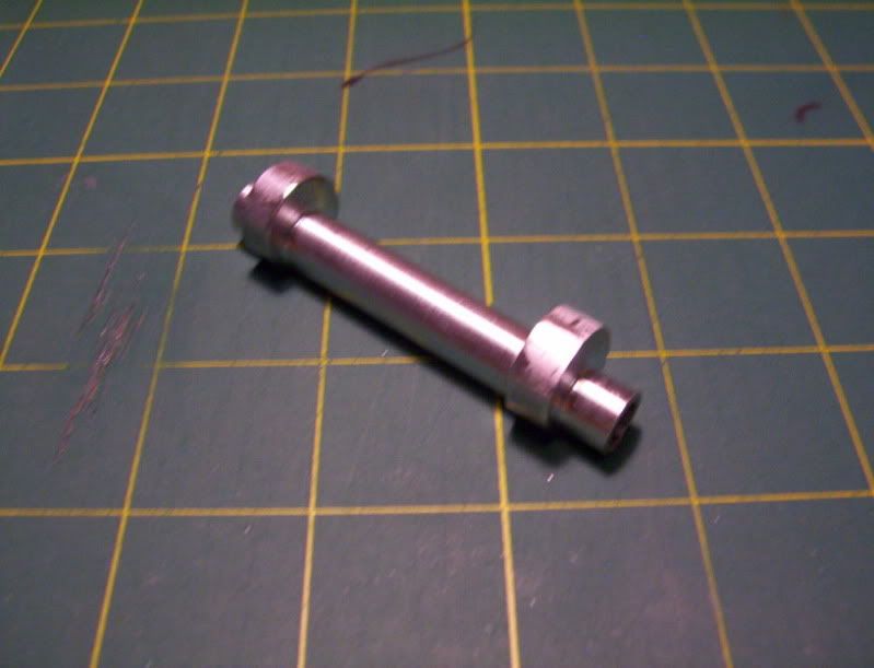
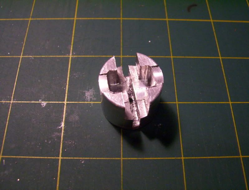
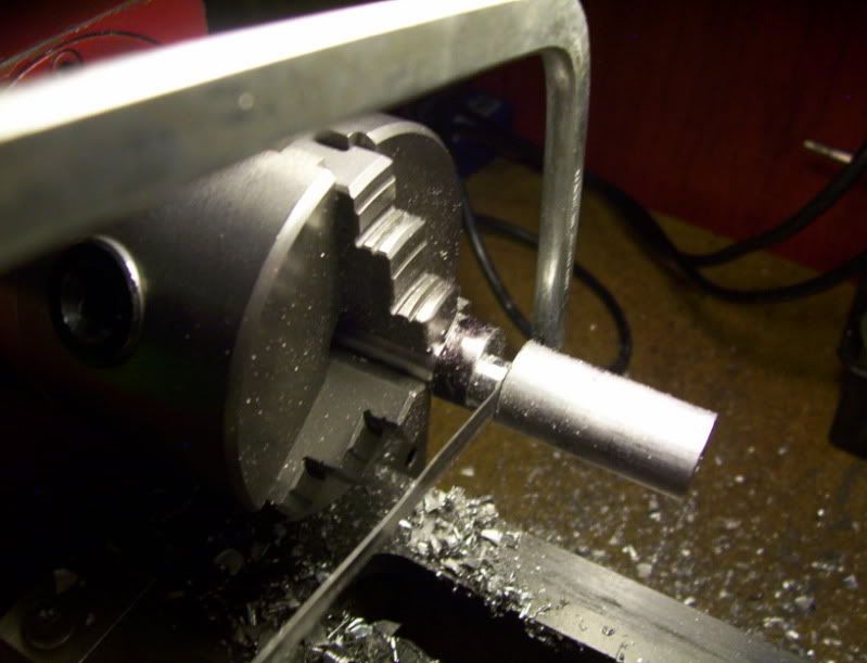
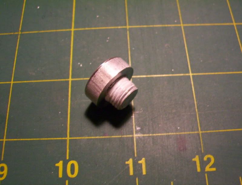
Now its time to make the top plunger, that will rest on the spring and glide over the base and have a stop after it traveles for 1/8". This plunger will be 2" in length.
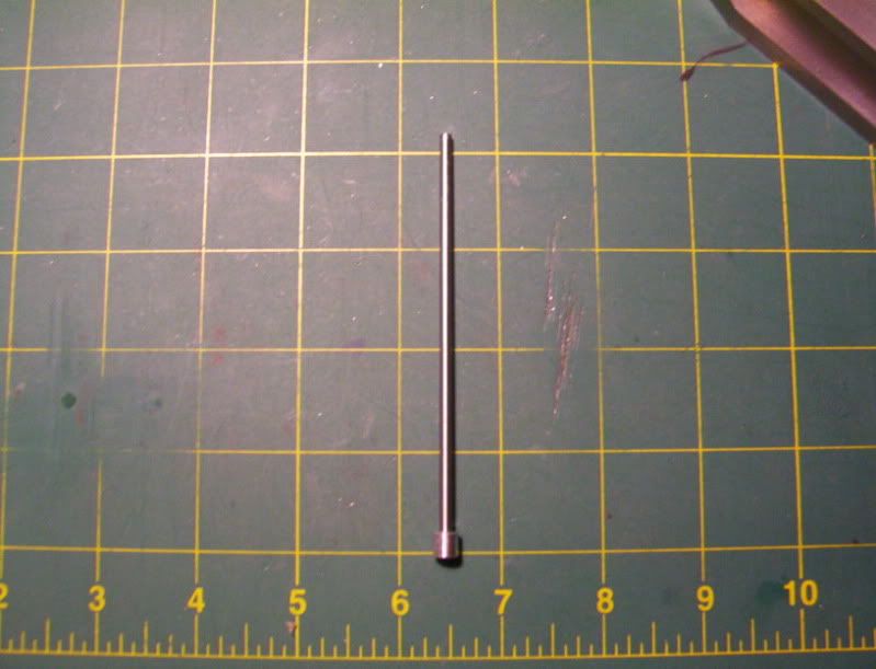
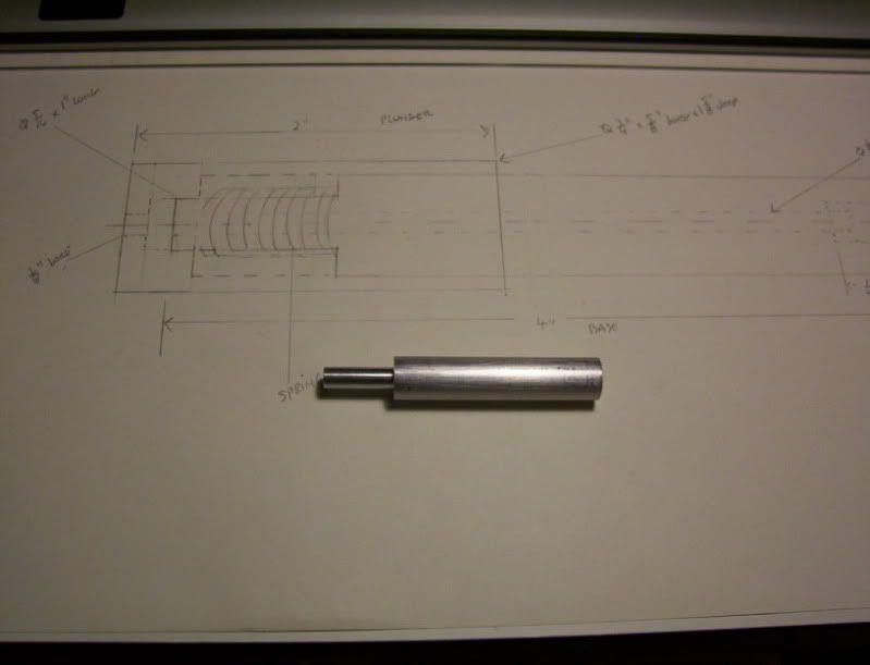
Here is the plunger blank machined to final length of 2"
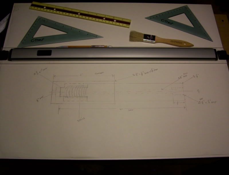
And the drawings for the dimensions.
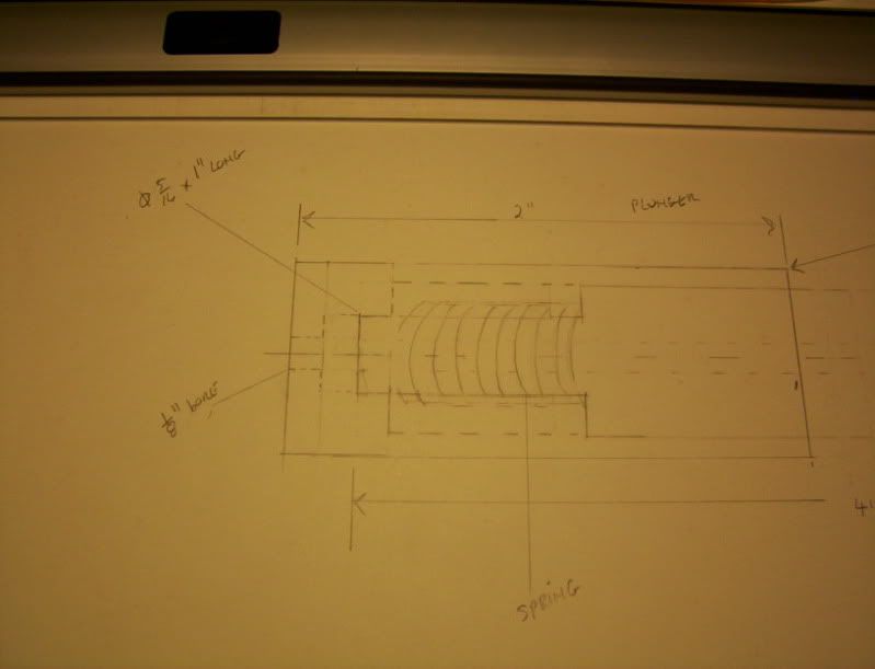
this will be done in 3 phases.
The first will be a thru hole 1/8" dia.
after that I will drill a 19/64" hole 1-7/8" deep, followed by a 5/16" reamer.
phase 2, I need to drill a 1/2" dia. hole 1-5/8" deep.
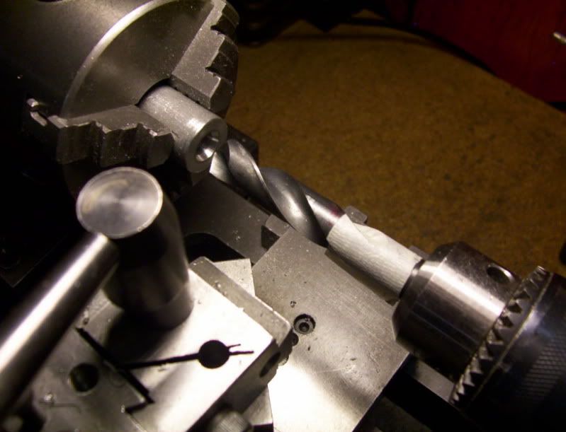
Phase 3. now bore this hole to a final insde dia. of 5/8" - 0.626" by 1-5/8" deep to make a sliding fit with the 5/8" base previously made.
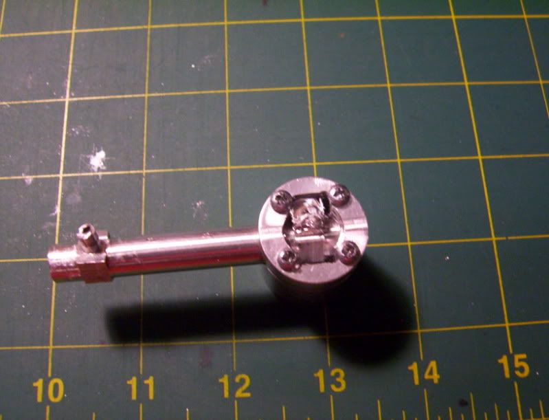
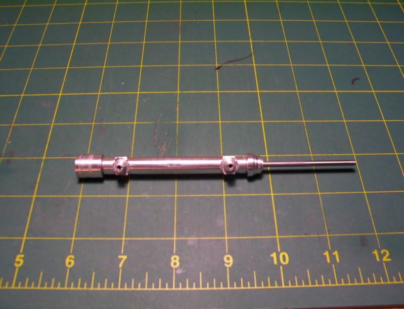
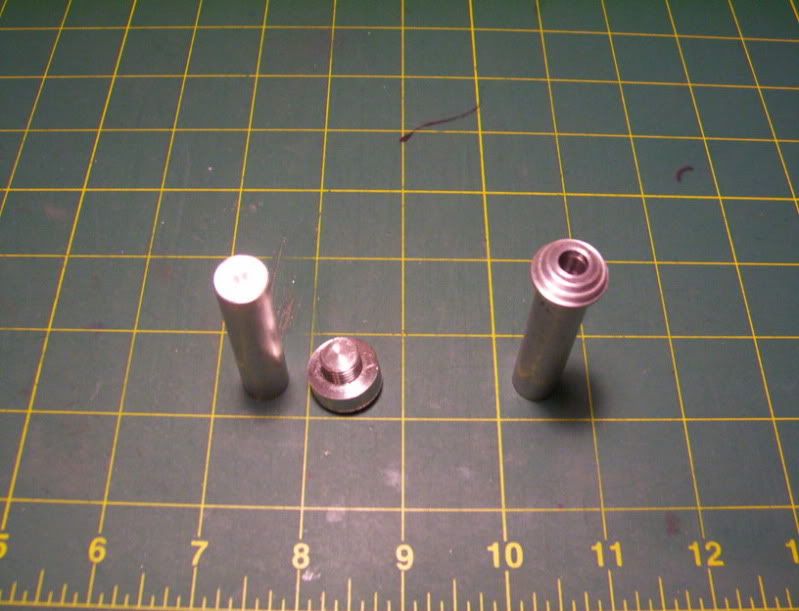
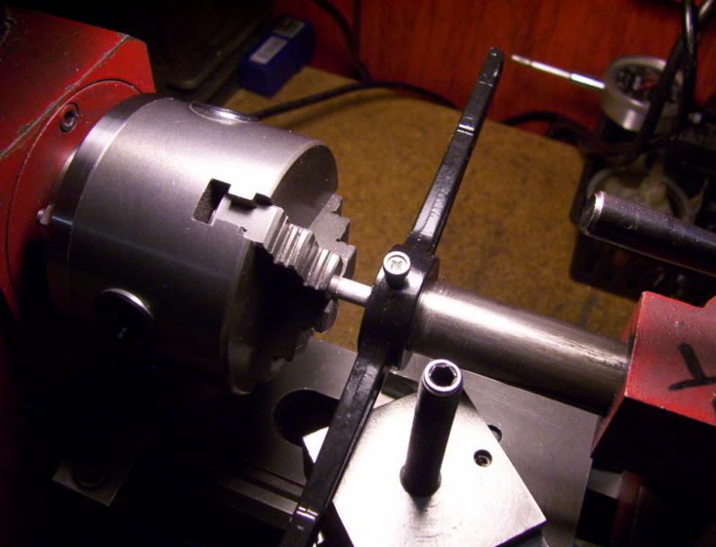
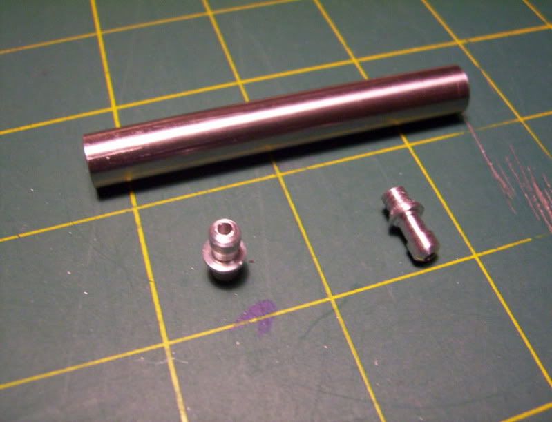
Now the parts before assembly
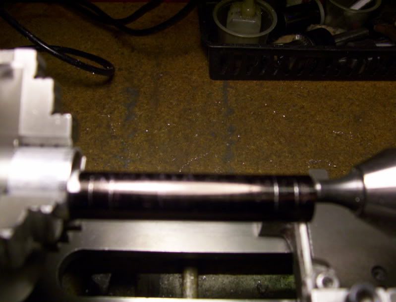
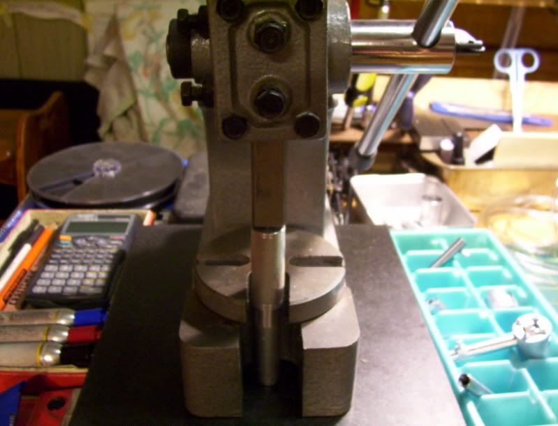
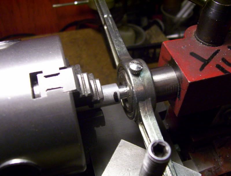
And the jig in it's final assembled stage.
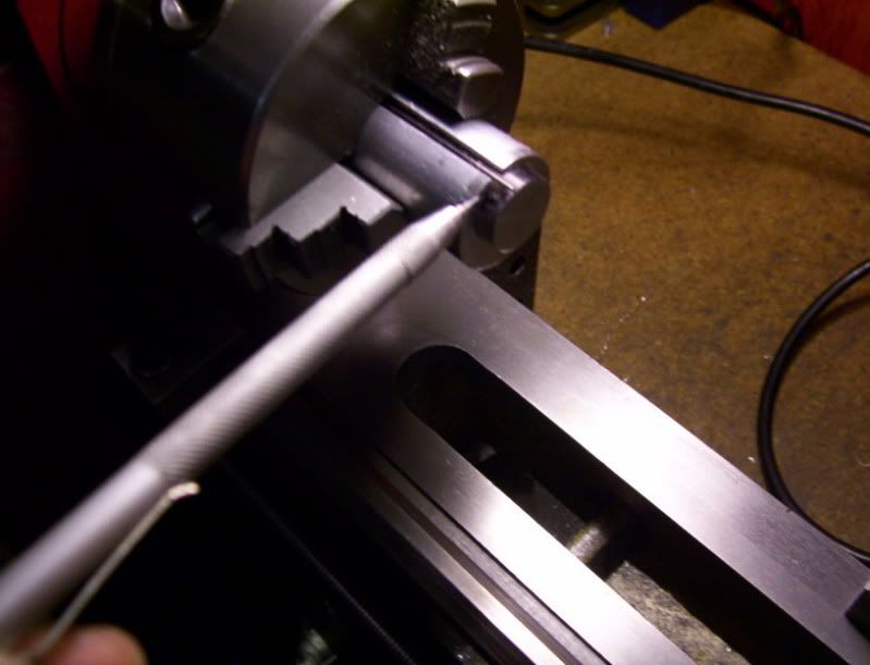
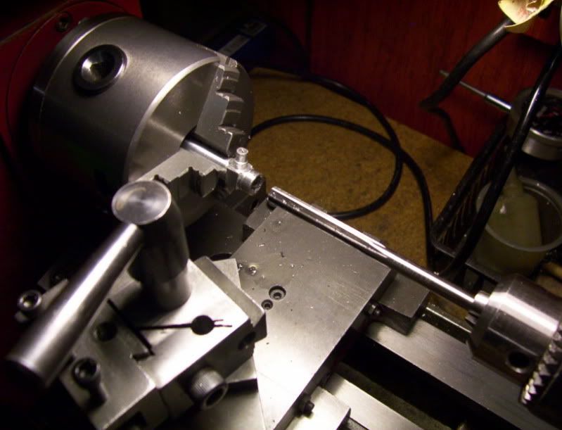
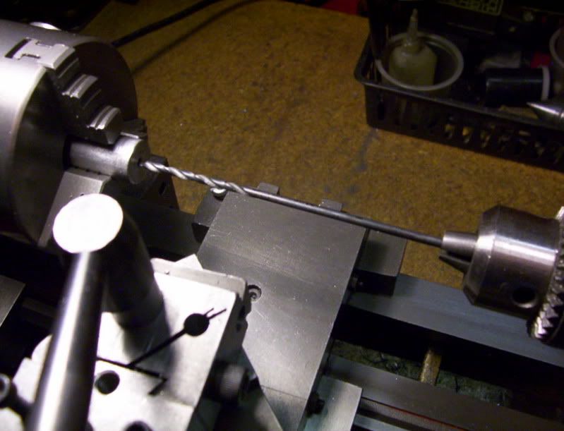
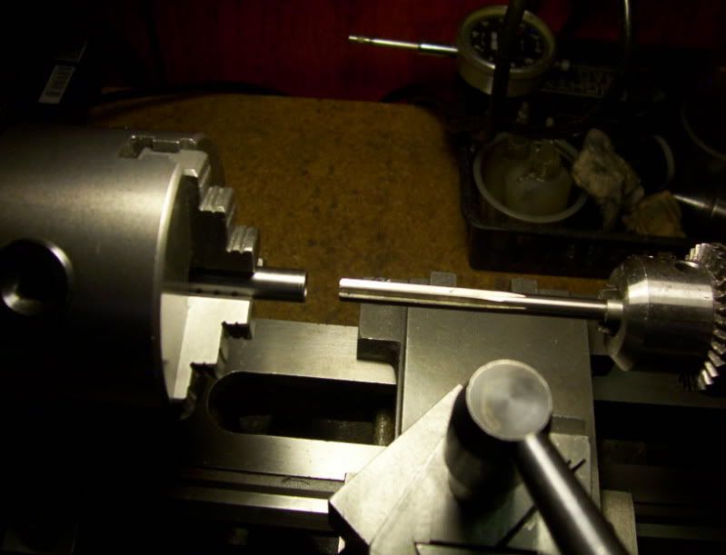
Now a 36" drill rod 1/8" dia. is slid through this jig, to test the accuracy of the assembly.
it slides with no excessive play along the entire length of the drill rod, very presisely done, so this may work in supporting the rod from bending during a press operatiopn.
The way this should work would be, the machined piston will be loaded at the bottom of this jig, then a 1/8" dia. drill rod machined to exact length, will be loaded at the top of the jig, the top of the rod should be just about flush with the top of the plunger cap, that is resting on the spring, now placing the jig under my small manual press, I should be able to press the rod into the piston, for an depth of 1/8" before the plunger hits its stop thereby keeping consistancy with every pressed rod. The spring does nothing more than keeps the cap plunger around 1/8" floating above the base stop. Thereby preventing any bending to occur imediately at the top of the rod where it will be pressed against.
This completes the first part of this project,
----------------------------------------------------------------------------------------------------------
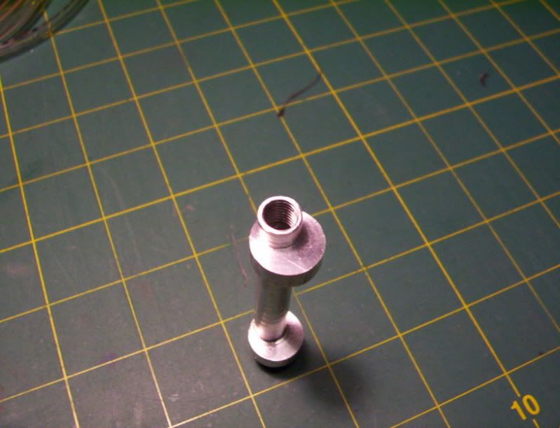
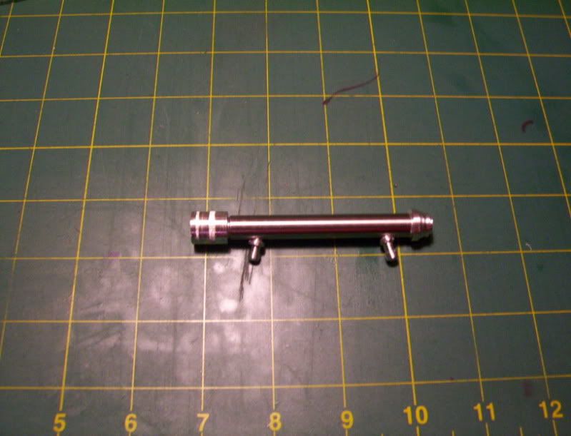
Now time to build a miniature cylinder:
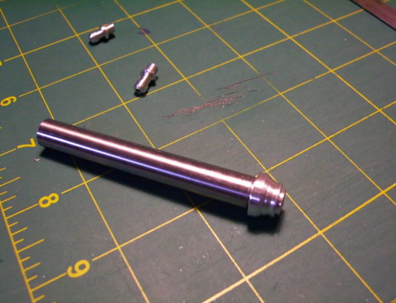
I will use a 3/8" dia. steel rod for the cylinder.
In order to get an accurate inner bore 1/4" dia. it needs to be a thru hole drilled and reamed,
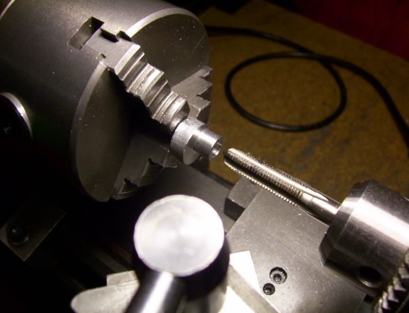
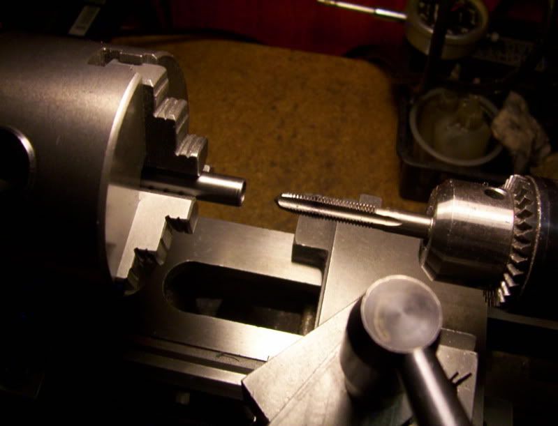
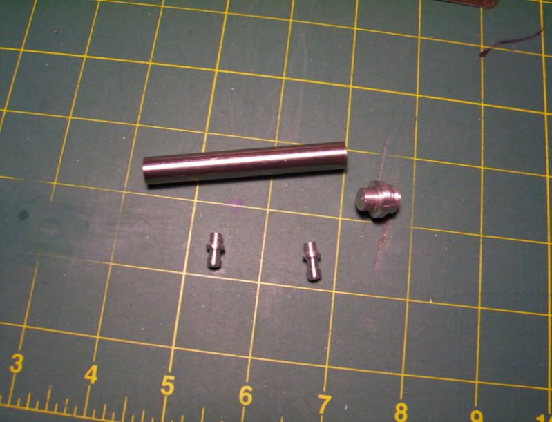
than to cap off both ends with appropriate fittings, I need to drill and tap for 5/16-24 threads on each end for a depth of 1/4"
---------------------------------------------------------------------------------------------------------------------
That's all for now, next the piston rod:
I have a few mechanical model projects I would, like to design and build,
using hydraulics, so this is going to be a experimental project in designing tooling and such, to be able to fabricate micro-miniature double acting hydraulic systems.
Building a single acting cylinder in hydraulics, is easy because there is no need to have a seal at the top of the cylinder, to contain the fluids, as long as the piston to cylinder fitting, is properly done with good compression, and very minute leakage, at the top.
But designing and building a double acting cylinder is more of a challenge, as I need to cap off both the bottom and top, of the cylinder for fluid pressure to push the piston in both directions.
I have decided I want to make a hydraulic system with a 3/8" dia. steel rod, with an internal bore dia. 1/4", so a piston with a dia. 0.249", and a length of 1/4" can be used and the piston rod to be made of 1/8" drill rod.
I looked at the idea of using my follower rest on my lathe, and makeing the piston and rod one piece, however I want the rod to be over 3", and to get a precise turning cut that way for that long of length could run into bending problems, somewhere if not some inconsistant rod diameter.
So I decide it would be best to use 1/8" precision rod, (drill rod) that ensures perfect dia. along the length of the rod. This means now I need to make the piston and rod 2 seperate pieces.
I thought about threading the piston and rod, than assembling together and then machining the piston down to final diameter. Or to press fit a aluminum piston, already to finished diameter, onto the rod.
I decided to go with the press fit method. This means to keep the 1/8" dia. rod from bending, I would need to fabricate a dedicated pressing jig, that I could utilize on my manual press.
I look at a project as being not only the finished work itself, but all the tooling and setups needed to be made in order to build and complete the project.
So building tooling is all part of building the final project itself.
-----------------------------------------------------------------------------------------------------
So here is a run down of what I have done so far, in fabricating a pressing jig:
Since this is a work in progress thread, I will give a lot of detail as possible.
The idea of this design is to press the 1/8" dia. 4" long rod onto a piston, 1/4" dia. x 1'4" long, for
a depth of 1/8".
This jig must support the rod along its entire length, as best as possible, so my design uses a solid rod, and a top plunger, spring loaded.
I start out by machining a 5/8"dia. rod to 4" overall length, measuring the length of the spring and its inner dia. shows I need to maching a stem on the end of this rod 5/16" in diameter, for a 1" length.
.
Now to support the 1/8" dia. drill rod its entire length I need to take my time and precisely drill the work piece with a thru hole of 1/8" dia., then finish it with a 0.126" reamer.
So I need to use my smallest 1/8" screwmachine size drill bit, followed by a 1/8" jobber size, finally following that with my 1/8" aircraft size bit.
Now I'll ream it with the 0.126" reamer as far as it can go.
Before I take the workpiece out of the chuick to turn it around to finish thru with the reamer from the other side, I need to drill and ream for a 0.249" hole 1/4" deep at the bottom of the workpiece.
Now I can turn the workpiece end for end to finish the reaming thru the workpiece.
Now here it is with the thru hole as precisely as possible drilled and reamed through, and the spring that will slide on top of it.
Now its time to make the top plunger, that will rest on the spring and glide over the base and have a stop after it traveles for 1/8". This plunger will be 2" in length.
Here is the plunger blank machined to final length of 2"
And the drawings for the dimensions.
this will be done in 3 phases.
The first will be a thru hole 1/8" dia.
after that I will drill a 19/64" hole 1-7/8" deep, followed by a 5/16" reamer.
phase 2, I need to drill a 1/2" dia. hole 1-5/8" deep.
Phase 3. now bore this hole to a final insde dia. of 5/8" - 0.626" by 1-5/8" deep to make a sliding fit with the 5/8" base previously made.
Now the parts before assembly
And the jig in it's final assembled stage.
Now a 36" drill rod 1/8" dia. is slid through this jig, to test the accuracy of the assembly.
it slides with no excessive play along the entire length of the drill rod, very presisely done, so this may work in supporting the rod from bending during a press operatiopn.
The way this should work would be, the machined piston will be loaded at the bottom of this jig, then a 1/8" dia. drill rod machined to exact length, will be loaded at the top of the jig, the top of the rod should be just about flush with the top of the plunger cap, that is resting on the spring, now placing the jig under my small manual press, I should be able to press the rod into the piston, for an depth of 1/8" before the plunger hits its stop thereby keeping consistancy with every pressed rod. The spring does nothing more than keeps the cap plunger around 1/8" floating above the base stop. Thereby preventing any bending to occur imediately at the top of the rod where it will be pressed against.
This completes the first part of this project,
----------------------------------------------------------------------------------------------------------
Now time to build a miniature cylinder:
I will use a 3/8" dia. steel rod for the cylinder.
In order to get an accurate inner bore 1/4" dia. it needs to be a thru hole drilled and reamed,
than to cap off both ends with appropriate fittings, I need to drill and tap for 5/16-24 threads on each end for a depth of 1/4"
---------------------------------------------------------------------------------------------------------------------
That's all for now, next the piston rod:


![DreamPlan Home Design and Landscaping Software Free for Windows [PC Download]](https://m.media-amazon.com/images/I/51kvZH2dVLL._SL500_.jpg)