
You are using an out of date browser. It may not display this or other websites correctly.
You should upgrade or use an alternative browser.
You should upgrade or use an alternative browser.
DIY Tesla Impulse Turbine
- Thread starter Toymaker
- Start date


Help Support Home Model Engine Machinist Forum:
This site may earn a commission from merchant affiliate
links, including eBay, Amazon, and others.
Another paper on the tesla pump with a chart of head pressure.
Hmmmm,...the Tesla pump they used in their study was only 9 cm (3.54") in diameter and their rpm maxed out at 2160. Without going through any math, that seems woefully too slow for a Tesla pump, (or even a centrifugal). Perhaps this study is ONLY for liquids and not gases (air)
Even for liquids, that seems slow. I think it stalled as a result which is visible in it's lower head readings. My .02$
I've been attempting to calculate how much power my small centrifugal water pump will use when driven by my Tesla Impulse turbine, but I have failed to find all the equations I need.
Here's what I have so far:
The power needed to drive centrifugal pump is as follows:
Power (kW) = Q x P x SG / 3600 X efficiency
Where:
Q = Flow Rate (m^3/hr)
P = Pressure (Bar)
SG = Specific Gravity of Water = 1
To use the above equation, I need to know Q, the flow rate. Multiple web pages give the following equation to find flow rate:
Q = (π * D^2 * n * H) / (4 * g)
Where:
D = Impeller Diameter
n = RPM
H = Head
g = Gravitational Constant (9.8 m/s^2)
However, I don't understand how this equation is complete without factoring in impeller blade height at the impeller exit.
Where's the equation that factors in blade height ??
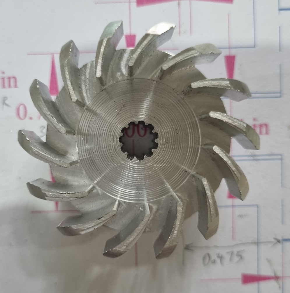
My impeller (below) is rather small: 48.78mm OD and blade height = 12.01mm. The small diameter is because I expect rpm in the range of 100,000 +/-.
Here's what I have so far:
The power needed to drive centrifugal pump is as follows:
Power (kW) = Q x P x SG / 3600 X efficiency
Where:
Q = Flow Rate (m^3/hr)
P = Pressure (Bar)
SG = Specific Gravity of Water = 1
To use the above equation, I need to know Q, the flow rate. Multiple web pages give the following equation to find flow rate:
Q = (π * D^2 * n * H) / (4 * g)
Where:
D = Impeller Diameter
n = RPM
H = Head
g = Gravitational Constant (9.8 m/s^2)
However, I don't understand how this equation is complete without factoring in impeller blade height at the impeller exit.
Where's the equation that factors in blade height ??
My impeller (below) is rather small: 48.78mm OD and blade height = 12.01mm. The small diameter is because I expect rpm in the range of 100,000 +/-.
Sorry I only dabbled is variable displacement pumps and have nothing to offer regarding equations, but you could always put a bucket X feet up to get a head and calculate that water columns are roughly 2.2 feet per pound, if memory serves.
The measure flow rate and multiply it out.
Very nice impeller.
The measure flow rate and multiply it out.
Very nice impeller.
Sorry I only dabbled is variable displacement pumps and have nothing to offer regarding equations, but you could always put a bucket X feet up to get a head and calculate that water columns are roughly 2.2 feet per pound, if memory serves.
The measure flow rate and multiply it out.
Very nice impeller.
Yep,... seems I'm at the point where I need to run a test to determine actual results.
My current plan is to plumb the pump the same way as a pressure washer, directing the pump's output through a very small orifice while reading the pressure with a dial guage. The pump input will be connected to a flowmeter. Pump output stream is directed back into the water supply tank that feeds the pump, thereby recirculating the water. If all goes as planned, I can use the pump power equation, kW = P x Q / 600, to find kW developed by the Tesla Impulse turbine.


$39.99
$49.99
Sunnytech Low Temperature Stirling Engine Motor Steam Heat Education Model Toy Kit For mechanical skills (LT001)
stirlingtechonline
$59.99
Sunnytech Hot Air Stirling Engine Motor Model Educational Toy Electricity Generator Colorful LED (SC001)
stirlingtechonline


$99.99
AHS Outdoor Wood Boiler Yearly Maintenance Kit with Water Treatment - ProTech 300 & Test Kit
Alternative Heating & Supplies


$156.90 ($1.40 / oz)
Replacement Combustion Chamber Kit, Burnham V8 and V8H, 1-6 Sec, 108136-01, 1129
Lynn Manufacturing


$94.99
$109.99
AHS Woodmaster 4400 Maintenance Kit for Outdoor Wood Boiler Treatment
Alternative Heating & Supplies


$190.00
$254.99
Genmitsu CNC 3018-PRO Router Kit GRBL Control 3 Axis Plastic Acrylic PCB PVC Wood Carving Milling Engraving Machine, XYZ Working Area 300x180x45mm
SainSmart Official


$99.99
$109.99
AmTech300 - Boiler Treatment Professional Strength (Rust Inhibitor For Outdoor Wood Boilers)
Alternative Heating & Supplies


$403.09
DM14 Engine Build Kit, Metal Engine Build Model Great Metal Material for Engineer for Factory
Easoger Official


$519.19
$699.00
FoxAlien Masuter Pro CNC Router Machine, Upgraded 3-Axis Engraving All-Metal Milling Machine for Wood Acrylic MDF Nylon Carving Cutting
FoxAlien Official


$188.98
TM NEXDYNAMI RE41157 Water Pump Compatible With/Replacement For/John Deere 6200 7400 6300 6600 6500 6400 7220 7600 7200 RE41157
VIVID MARKET CORPORATION

$45.99
Sunnytech Mini Hot Air Stirling Engine Motor Model Educational Toy Kits Electricity HA001
stirlingtechonline


I'm wondering if you need a speed reducer, I've never heard of an impeller running so fast.
You might have issues with cavitation?
Have you designed a blower yet? Are you going axial or centrifugal?
You might have issues with cavitation?
Have you designed a blower yet? Are you going axial or centrifugal?
I'm wondering if you need a speed reducer, I've never heard of an impeller running so fast.
Due to the small diameter of the impeller, tip speed is only 255 meters per second, which is well under the 343 m/s speed of sound in water. My knowledge of impeller design is mostly with compressible fluids; in air, as long as tip speed is kept below Mach 1, the impeller will likely work. I don't know if that holds true with incompressible fluids.
You might have issues with cavitation?
I strongly suspect I will have cavitation problems, especially since the pump's suction side intake is the same size as the pressure side outlet. Ideally, I believe I should double the intake diameter, but doing so makes plumbing much more difficult.
If during testing, the pump appears to be choked, first I'll attach an RO pump to the intake of the centrifugal pump to force water into the suction side. If that fails, I'll open the inlet diameter and run the pump submerged.
Have you designed a blower yet? Are you going axial or centrifugal?
Centrifugal is best for my needs. I already have an impeller taken from a large turbocharger (115mm OD, 70mm eye) for which I need to make a housing,...this will be my starting point.
Last edited:
It seems to me to be a complete mismatch of technology to fit a centrifugal water pump powered by a Tesla surface friction turbine - with totally different characteristics of power, torque, versus speed, fluid type and density, etc.
Surely the obvious choice would be a Tesla water pump powered by a Tesla gaseous turbine? Or a vaned water pump powered by a vaned gaseous turbine?
Just an opinion without the numbers for what you are doing...
As Engineers can design anything (though many things are "useless" or "just because they can") you can of course do what you are doing, but it seems you are designing numerically, after having made some bits... I.E. your process is back to front.
Surely, (maybe with that rare tool called Hindsight?) it would have been more appropriate to design by calculation before making any bits, so you can get it right - or near right - before cutting metal?
I have made such errors and learned about hindsight!
GOOD LUCK with your calculations. I don't have the knowledge/expertise to tell you any more than Google. (I use Engineers Toolbox a lot. Have you tried it?
https://www.engineeringtoolbox.com/
ENJOY doing as we enjoy hearing of your fun.
K2
Incidentally, a Tesla disc turbine with smooth shaped discs does not generate large pressure differences such as seen on screw propellers and centrifugal rotors, so cavitation in the fluid should not occur. The low pressure zone - where cavitation could occur, is at the centre boss of the discs, running at relatively slow speed (and minimum diameter) and the pressure gradient is a series of many small steps as the fluid moves outwards to the perimeter.
Conversely, a bladed rotor has a surface with high pressure on one side and very low pressure developed at the outer diameters of the other side. The high and low pressure interface is just across the outer edge on the rotor's blades, so would normally be very close to the casing (at some point) to minimise "back-flow" of fluid and loss of performance, as well as potential cavitation. - I think?
K2
It seems to me to be a complete mismatch of technology to fit a centrifugal water pump powered by a Tesla surface friction turbine - with totally different characteristics of power, torque, versus speed, fluid type and density, etc.
Surely the obvious choice would be a Tesla water pump powered by a Tesla gaseous turbine? Or a vaned water pump powered by a vaned gaseous turbine?
Just an opinion without the numbers for what you are doing...
As Engineers can design anything (though many things are "useless" or "just because they can") you can of course do what you are doing, but it seems you are designing numerically, after having made some bits... I.E. your process is back to front.
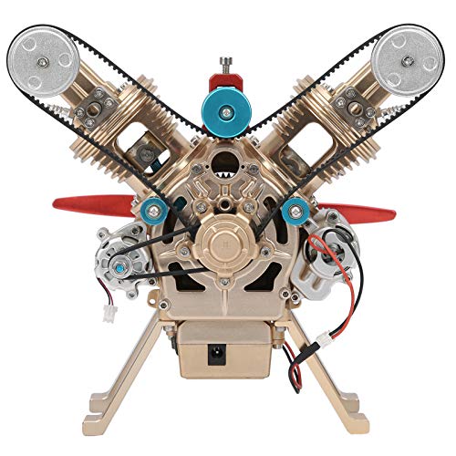
If you review post #2, you'll see the below photo showing the current water pump attached to the Tesla turbine which is itself connected to my shop air compressor tank for initial testing. The pump and turbine share a common shaft because they were both designed to work together from the start.

Surely, (maybe with that rare tool called Hindsight?) it would have been more appropriate to design by calculation before making any bits, so you can get it right - or near right - before cutting metal?
I have made such errors and learned about hindsight!
GOOD LUCK with your calculations. I don't have the knowledge/expertise to tell you any more than Google. (I use Engineers Toolbox a lot. Have you tried it?
https://www.engineeringtoolbox.com/
ENJOY doing as we enjoy hearing of your fun.
K2
The photo below was taken from the video in post #17 which demonstrated that my Tesla turbine works well enough on a very limited amount of compressed air,& powering my water pump, to warrant further development by proceeding to steam tests.

Calculate the units for flow for this equation problem: Q <m^2*s>= (π * D^2 <m^2> * n<s^-1> * H<m>) / (4 * g)<s^2*m^-1> This isn't the unit for flow.I've been attempting to calculate how much power my small centrifugal water pump will use when driven by my Tesla Impulse turbine, but I have failed to find all the equations I need.
Here's what I have so far:
The power needed to drive centrifugal pump is as follows:
Power (kW) = Q x P x SG / 3600 X efficiency
Where:
Q = Flow Rate (m^3/hr)
P = Pressure (Bar)
SG = Specific Gravity of Water = 1
To use the above equation, I need to know Q, the flow rate. Multiple web pages give the following equation to find flow rate:
Q = (π * D^2 * n * H) / (4 * g)
Where:
D = Impeller Diameter
n = RPM
H = Head
g = Gravitational Constant (9.8 m/s^2)
However, I don't understand how this equation is complete without factoring in impeller blade height at the impeller exit.
Where's the equation that factors in blade height ??
My impeller (below) is rather small: 48.78mm OD and blade height = 12.01mm. The small diameter is because I expect rpm in the range of 100,000 +/-.
Hi Toymaker, Thanks, Yes I remember the earlier posts. The Tesla turbine is a large diameter, the pump very small, so may be balanced for torque and speed, but I am guessing you are now asking about calculations, because they were not quite right when you initially decided the sizes, speeds, etc. for the flow you need...? It seems (in my feeble brain?) that a Tesla Turbine designed for a Tesla Pump will be the similar technology (except the fluids are different) so may be similar in performance characteristic? From your recent posts I get a feeling that you think your pump is not right for the turbine. - That is all. Not a criticism, just sharing ideas.
Don't waste your time with my ponderings if you wish, I am not offended. I just like to understand what you are doing and learn from it as appropriate, when I am below your understanding and cannot really help with your questions.
You are doing a grand job, so don't let me waste your time if my ideas are no use.
Cheers,
K2
What is the free running speed for your turbine? What flow rate of water do you need for your flash boiler? (Derived from the needs of the prime mover and available burner power, I guess?).
What else connects to the boiler, demanding steam, and at what pressure and superheat temperature do you expect to generate?- It is probably somewhere in the previous 250 posts... But it may be quickest if you know ...?
Thanks,
K2
What else connects to the boiler, demanding steam, and at what pressure and superheat temperature do you expect to generate?- It is probably somewhere in the previous 250 posts... But it may be quickest if you know ...?
Thanks,
K2
Hi Toymaker, Thanks, Yes I remember the earlier posts. The Tesla turbine is a large diameter, the pump very small, so may be balanced for torque and speed, but I am guessing you are now asking about calculations, because they were not quite right when you initially decided the sizes, speeds, etc. for the flow you need...?
You've made an understandable assumption, but the real reason for the calculations is slightly more complicated and best explained by referencing my post #633 in the "Monotube Flash Boiler" thread where I stated:
I will need a MUCH bigger alternator coupled to the turbine to perform useful testing.

After determining that 20 kW steam output was the low end for my boiler's output, I was faced with the facts that a 20 kW alternator would be quite large and would never spin at the high rpms of the Tesla turbine; therefore, if I used an alternator as the load on the boiler, I would also need a speed reduction gear set capable of handling 20 kW.
At some point in my brainstorming, and failed searches for a speed reducer, I realized that I may already have the steam load I need,...my Tesla turbine powered water pump might just work. But how will I know how much power the water pump is actually using? Knowing that answer would be very useful in determining power generated by the Tesla turbine.
From your recent posts I get a feeling that you think your pump is not right for the turbine.
If I've given you that impression, than I have failed to effectively communicate,...and that's on me.
I actually believe that a centrifugal pump is an ideal match for a Tesla turbine, as both function best at high rpm.
Although I do have concerns that the water pump may induce cavitation due to high rpm, that will not be a show stopper. I'm much more concerned that the current suction side of the pump is too small, but I've given solutions for this possible occurrence too.
By noting these possible problems, I'm simply looking ahead for trouble, and attempting to find solutions.
Last edited:
Calculate the units for flow for this equation problem: Q <m^2*s>= (π * D^2 <m^2> * n<s^-1> * H<m>) / (4 * g)<s^2*m^-1> This isn't the unit for flow.
Do you have an equation to calculate flow rate through a centrifugal water pump which includes impeller blade height or thickness?
Possibly there is something of use here?
https://duckduckgo.com/?q=centrifugal+pump+flow+rate+chart&atb=v442-1&ia=web
Or here?
https://duckduckgo.com/?q=flow+rate+of+centrifugal+pump+formula&atb=v442-1&ia=web
But I guess you have already searched anyway?
Thanks for the advice in #255. I think I follow where you are now.
Enjoy!
K2
https://duckduckgo.com/?q=centrifugal+pump+flow+rate+chart&atb=v442-1&ia=web
Or here?
https://duckduckgo.com/?q=flow+rate+of+centrifugal+pump+formula&atb=v442-1&ia=web
But I guess you have already searched anyway?
Thanks for the advice in #255. I think I follow where you are now.
Enjoy!
K2
What is the free running speed for your turbine?
I will measure the rpm of the turbine once I connect it to my boiler. For now, I've estimated free running rpm will be aprox 160,100,...this number is based on the assumption that linear velocity at the turbine disk's circumference (ie tip speed) will equal steam velocity from the nozzles which should be the speed of sound in steam at local pressure and temperature, which is about 500 meters/sec.
What flow rate of water do you need for your flash boiler? (Derived from the needs of the prime mover and available burner power, I guess?).
I measured boiler flow rate at the boiler's lowest output level in post #632 of the Monotube Flash Boiler Design thread..... which is 0.5 LPM. I'll post max consumption after I've done more testing.
What else connects to the boiler, demanding steam,
The only steam consumer will be a turbine of some kind,...hopefully a scaled up version of the current Tesla Impulse turbine.
and at what pressure and superheat temperature do you expect to generate?- It is probably somewhere in the previous 250 posts... But it may be quickest if you know ...?
Thanks,
K2
As you may recall, my boiler uses copper tubes, which limit both steam pressure and temperature. Absolute max never exceed limits will be 500 psi at 243 C. Max normal operating limits will be 400 psi at 231 C.
Thanks Toymaker, yes I remember which project this is now. Just observations, as I am no expert on Flash boilers! (Or any other boilers. But I have repaired more than I have made, and only about a dozen in total. - including scrapping BAD designs.).
I have done some boiler calculations, and as there are also University research papers, etc. on the calculations, have "an opinion" of what I think is a "safe" limit for Model Engineers.
I realise your boiler is beyond being just a model, and as such suggest that the ASME boiler limits (for stress and temperature for steam boilers, etc.) are reasonable - to avoid catastrophic failures. I also understand that the Chemical nuclear and rocket industries always do their own thing, because they have the money, people, etc. to prove what they are doing is safe... - ish. I wonder if NASA thinking 1% failure rate of rockets in the 1960s would pass judgement today? But their pressure vessels and systems are not known to have failed in normal use. And at times of War, all things are driven to extremes, so higher stresses are used everywhere... So ASME doesn't cover all scenarios.
But musings aside:
ASME (A bunch of clever American engineers who are trying to protect people from the law courts) suggest that "Silver-Soldered copper boilers do not exceed 100psi" = 205deg.C.
Although I reckon there are a lot of boilers made to "old" designs that exceed this - e.g. in the UK there are many older locos with copper boilers and superheater tubes at more than 100psi. 205C. - It is recognised that these do not relate to today's perspective of ASME regulations in the USA, or equivalent in Australia, etc...
BUT this (ASME Regulations) allows (effectively) for a Factor of safety of 8 on yield stress at elevated temperature, but it also includes for various stress concentration factors of various shapes of stressed boiler parts to be considered in the design calculations. (Stress concentrations can be the "killer" in many designs).
In conclusion, I am sure you will have considered many things in your flash boiler design, but using copper at 400psi may be working a bit closer to the limit than most would consider safe. While some say the max safe working stress for copper is around 6300psi. at <60C, at 205C (100 psi) this is de-rated to about 3000psi for the SAFE tensile stress limit. I do not have a tensile stress limit at 243C, but assume this must be significantly below 3000psi. Added to which, the making of a flash boiler using bent tubing will create thinner zones of material, and some local stress raisers? - You know your design, so I hope you have confirmed any stress concentration factors and appropriate wall thinning stress concentrations in your calculations.
While "Flash" boilers contain MUCH less water than "Conventional" boilers (as covered by ASME etc.), your boiler can still have many lbs of hot copper, hot water, and steam, in a confined space with a powerful burner, so still poses some risk (from escaping steam, etc?) in the event of failure (eg. a burst tube). So please be careful with your design, and try and consider all the things that could possible go wrong before working it up to your planned working pressure. I am the far side of the planet, so unlikely to hear screams from Thailand. I prefer there to be only screams of delight!
Also, I wonder what material you have used for the plates of the Tesla Turbine, as Tesla had severe problems of distortion (Caused by Differential expansion due to the temperature change across the plates?) with his turbines, exacerbated by the centrifugal stresses at very high speed. 160000rpm sounds a bit high for "normal" materials?
I have been trying to run at the other end of the scale: The Tesla Turbine is only about 3in diameter, and the steam supply is limited (I only have a little boiler available for this!) so I am running at 30psi, with little superheat, and getting 20000rpm free-running. The exhaust steam is very wet, but when hot it seems to not have residual water inside the turbine, but I needed to add a tiny drain hole in the casing to expel water during cold starting and warm-up phases. Otherwise it simply became a condenser half-full of water...
"Good luck" = wrong... I truly wish you to be a Good Engineer and not have need of luck with this one.
K2
Thanks Toymaker, yes I remember which project this is now. Just observations, as I am no expert on Flash boilers! (Or any other boilers. But I have repaired more than I have made, and only about a dozen in total. - including scrapping BAD designs.).
I have done some boiler calculations, and as there are also University research papers, etc. on the calculations, have "an opinion" of what I think is a "safe" limit for Model Engineers.
I realise your boiler is beyond being just a model, and as such suggest that the ASME boiler limits (for stress and temperature for steam boilers, etc.) are reasonable - to avoid catastrophic failures. I also understand that the Chemical nuclear and rocket industries always do their own thing, because they have the money, people, etc. to prove what they are doing is safe... - ish. I wonder if NASA thinking 1% failure rate of rockets in the 1960s would pass judgement today? But their pressure vessels and systems are not known to have failed in normal use. And at times of War, all things are driven to extremes, so higher stresses are used everywhere... So ASME doesn't cover all scenarios.
But musings aside:
ASME (A bunch of clever American engineers who are trying to protect people from the law courts) suggest that "Silver-Soldered copper boilers do not exceed 100psi" = 205deg.C.
Although I reckon there are a lot of boilers made to "old" designs that exceed this - e.g. in the UK there are many older locos with copper boilers and superheater tubes at more than 100psi. 205C. - It is recognised that these do not relate to today's perspective of ASME regulations in the USA, or equivalent in Australia, etc...
BUT this (ASME Regulations) allows (effectively) for a Factor of safety of 8 on yield stress at elevated temperature, but it also includes for various stress concentration factors of various shapes of stressed boiler parts to be considered in the design calculations. (Stress concentrations can be the "killer" in many designs).
In conclusion, I am sure you will have considered many things in your flash boiler design, but using copper at 400psi may be working a bit closer to the limit than most would consider safe. While some say the max safe working stress for copper is around 6300psi. at <60C, at 205C (100 psi) this is de-rated to about 3000psi for the SAFE tensile stress limit. I do not have a tensile stress limit at 243C, but assume this must be significantly below 3000psi. Added to which, the making of a flash boiler using bent tubing will create thinner zones of material, and some local stress raisers? - You know your design, so I hope you have confirmed any stress concentration factors and appropriate wall thinning stress concentrations in your calculations.
While "Flash" boilers contain MUCH less water than "Conventional" boilers (as covered by ASME etc.), your boiler can still have many lbs of hot copper, hot water, and steam, in a confined space with a powerful burner, so still poses some risk (from escaping steam, etc?) in the event of failure (eg. a burst tube). So please be careful with your design, and try and consider all the things that could possible go wrong before working it up to your planned working pressure. I am the far side of the planet, so unlikely to hear screams from Thailand. I prefer there to be only screams of delight!
Also, I wonder what material you have used for the plates of the Tesla Turbine, as Tesla had severe problems of distortion (Caused by Differential expansion due to the temperature change across the plates?) with his turbines, exacerbated by the centrifugal stresses at very high speed. 160000rpm sounds a bit high for "normal" materials?
I have been trying to run at the other end of the scale: The Tesla Turbine is only about 3in diameter, and the steam supply is limited (I only have a little boiler available for this!) so I am running at 30psi, with little superheat, and getting 20000rpm free-running. The exhaust steam is very wet, but when hot it seems to not have residual water inside the turbine, but I needed to add a tiny drain hole in the casing to expel water during cold starting and warm-up phases. Otherwise it simply became a condenser half-full of water...
"Good luck" = wrong... I truly wish you to be a Good Engineer and not have need of luck with this one.
K2
As always, I appreciate your concerns for my safety,...and you and I, along with other HMEM members, have already spent much time and many posts discussing the safety of my monotube boiler, so I will not re-address any specific issues here. I will only point out, again, that many SACA (Steam Automobile Club of America) members have constructed many copper tube boilers which they have been safely operating for years at 400 psi and 448 F, which they sometimes refer to as 4-by-4 boilers.
My Tesla turbine discs are made from aluminum and are only 61mm (2.4") diameter, which makes them a tiny fraction of the size of Tesla's steel turbine discs. Due to their tiny size and aluminum material, I don't have a scale small enough to weigh a disc. so I have no idea what each disc weighs, meaning I cannot use the centrifugal force equation: F=mV^2/r. However, I know that aluminum impellors in automotive turbochargers typically spin at 250,000 rpm without flying apart, so I'm not too concerned about exceeding stress limits.
I don't recall exactly, but I don't believe Tesla encountered disc warping problems with his desk-top sized turbine.
Similar threads
- Replies
- 2
- Views
- 2K
- Replies
- 3
- Views
- 2K