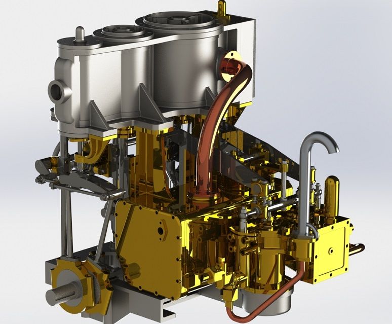
Compound Condensing Engine

Home Model Engine Machinist Forum

Help Support Home Model Engine Machinist Forum:

This site may earn a commission from merchant affiliate links, including eBay, Amazon, and others.
Well, you know what they say about kids with new toys? ;D

After postie delived a brilliant surprise this morning, I just couldn’t help myself at lunchtime and took the bedplate down to the mill to start the cleanup. My initial thought was that I wanted the pads on the top face to be of equal height, so I used the main upper face as a datum, with a pair of parallels and a couple of clamps, and skimmed the lower rails. I used whats possibly an unusual cutter for iron, a Kennametal high rake twin tipped 20mm facemill, and the iron cut like butter – absolutely beautiful. If the rest of the castings are even close to this one then we’re in for a stunner here!Thm:

Once those rails were clean I flipped it over on to a larger set of parallels, and it sat flawlessly level. Securing it again with a pair of clamps, I then cleaned the top face. It took around 1mm to clean up, but that was down to one of the bearing cap faces (at A) just being slightly low, but it’s no problem at all as there’s bags of material left.

I didn’t bother at all about any other faces being true, but at least now there are two datum faces to use for working out where we go from here. It’s been a fair while since I’ve machined any iron, but this was a pleasure, and with absolutely zero porosity or inclusions

Oh, and I did take a load of setup pics on my Ipod, so I’ll get those off tonight and post them ;o)

Overall, it has to be said that it's really great to get started on this, and proportion wise it promises to be a stunner!
woohoo1woohoo1woohoo1

DSC04519.jpg


DSC04518.jpg
 
Here we go, I finally dug the pictures from my Ipod of the two setups done so far ;D
Op1 referencing from the main upper face to clean the base, and the Op2 referencing from the cleaned face to skim the upper pads. Next job should be working out which side to get true first...

Bedplate - Op1.jpg


Bedplate - Op1-2.jpg


Bedplate - Op1-3.jpg


Bedplate - Op2.jpg


Bedplate - Op2-2.jpg


Bedplate - Op2-3.jpg


Bedplate - Op2-4.jpg
 
And the sides squared up, but not yet to size, in the same setup as the last op. ;D

Next job? Perhaps getting to final thickness before working out where to datum the part in X & Y...

Bedplate - Op3 - Squaring sides (1).jpg


Bedplate - Op3 - Squaring sides (3).jpg


Bedplate - Op3 - Squaring sides (4).jpg


Bedplate - Op3 - Squaring sides (5).jpg
 
Well I made some more progress on Friday and got the upper and lower faces to their final dimensions, and also cleaned up the bottom of the main bearing bolt bosses, and as usual everything is machining beautifully. The mill's tied up at the moment on another job, but the next op is programmed and ready to go - the spotting, drilling and reaming of the holes, and then rough and finish machining of the main bearing pockets, crank clearance, air pump passageways, and the profile around the air pump bore. I'm CNC'ing these, but if anybody would like a mock up of the manual steps then feel free to let me know.

Capture.jpg
 
And we're done on the bedplate machining! woohoo1

The part actually datummed really nicely in X & Y, so after drilling and reaming the bores I pocketed the main bearings, profiled around the casting to true it, and then lightly skimmed the top face.

Now off to the workshop for a nice filing and fettling session...

Dennis is progressing really well with the next pattern, which will be the flywheel, eccentric straps, main bearing caps, and the condensor, so all being well the progress will keep coming. I'm redrawing and checking the 2D drawings for this as we go too, so at the end of all this there shoudl be a nice safe set of plans.

Bedplate - Op4 - CNC (1).jpg


Bedplate - Op4 - CNC (2).jpg


Bedplate - Op4 - CNC (3).jpg


Bedplate - Op4 - CNC (5).jpg


Bedplate - Op4 - CNC (4).jpg


Bedplate - Op4 - CNC (6).jpg


Bedplate - Op4 - CNC (8).jpg


Bedplate - Op4 - CNC (9).jpg
 
Looks nice Dave,
I’m curious to see it after you work your magic with the files and sand paper.

Dave
 
Thanks, Dave!

Lol, I seem to live my life with files and sand paper these days - that flywheel for the entablature is driving me slowly insane :(
I don't think this will take too long to clean up, and there are a couple of spots to fill, but nothing major. I do still want it to look like a casting and not a billet though...
 
Centre main bearing halves sweated together, blocked up and grooved, and in for a trial fitting. I'll get the outers up to this stage, and then head scratch a way to line bore them with the equipment I have here...

Centre Main - 01.jpg
 
Oh, and seeing the shocking finish visible on the crank journal in this pic, I'd better add that it is only rough turned at present ;)
 
And here's the mains bored and faced to length, but I did have a senior moment and used an expanding mandrel to hold them for facing, and loosed the soldered joints, so to turn the concave rads on the end faces I'll either need to clamp them back together or interpolate it on the CNC...

DSC04607.jpg
 
And the mains finish turned and fitted - a pair of toolmakers clamps (and a cable tie) kept them together on the expanding mandrel. Next job perhaps the front columns...

DSCN0056.jpg
 
And the first fitting of the front columns ;D
The outer two are finish turned, while I just want to confirm one dimension before finishing the centre one, as what will be a square boss for mounting the reversing shaft is larger on this one to carry the worm & wheel.

DSCN0061.jpg


DSCN0062.jpg
 
I'm still pondering the finish turning on the crank (or being a big girl, one or the other!) so I thought the next job to start getting some motion underway would be the connecting rods. They're from 45mm steel bar, and to allow for distortion the first job I'm doing is to knock as much meat off of them as I can before leaving them a week or so to get any movement out of the way before finishing.

DSCN0071.jpg


DSCN0072.jpg


DSCN0073.jpg


DSCN0074.jpg


DSCN0075.jpg


DSCN0076.jpg


DSC04706.jpg
 
And some more progress - the rods are dowelled, assembled, and the big end milled to size ready for boring and profiling, the first rough op on the reversing wheel is off of the mill (and due for a LOT of finishing work!), and the propshaft flange is turned from stainless ready for drilling and broaching. I may not achieve my aim of getting the crank in by Xmas, but we won't be too far off :D

DSC04849.jpg


DSC04867.jpg


DSC04868.jpg


DSC04869.jpg
 
Well we've all made some more progress lately. Dennis is still working hard on the patterns, and last week received the first of the brass castings which is the condenser body. This has been cast in red brass, and overall the quality of the job is excellent, but it was found that the outside cores were a little loose and this has resulted in a casting that's around 0.28" too large on the top and side of the box. Dennis is playing with making some mods to the first casting, and in parallel with that modifying the cores to tighten everything up. For the first pour the foundry cut the gates and runners themselves by hand to see which worked best, and based on the results these will now be incorporated into the pattern. All being well there'll be a trip to both the iron and brass foundries in January after everybody is back to work and up to speed again.

I've been playing here too, taking the back off of the reversing wheel, which is now the subject of much verbal abuse while I profile the spokes (why, oh why did I start another wheel this close to the entablature wheel?? :wall:). Also the connecting rods are in the CNC having the bores finished to size and also the first profiling op on their upper ends...

Condenser - First raw casting (1).jpg


Condenser - First raw casting (2).jpg


Condenser - First raw casting (3).jpg


DSC04881.jpg


DSC04925.jpg


DSC04926.jpg
 
Lol, you and me both! At least we'll have both proven plans and castings for this stunning engine soon :)
 

Latest posts

Back
Top