CAD Exam - 5-Cyl Steam Radial

Home Model Engine Machinist Forum

Help Support Home Model Engine Machinist Forum:

This site may earn a commission from merchant affiliate links, including eBay, Amazon, and others.

Setarkos

Member
Joined
Mar 13, 2012
Messages
6
Reaction score
0
Hi everybody!

I'm making this thread of gratitude to this forum.
I'm currently working on my BS in Mechanical Engineering, as the final exam in 3D-modelling my class was given the task to make "a steam driven engine" in SolidWorks, either a copy of a working design or something new. My search for inspiration lead me to this forum where I've beed inspirated and educated.
Since English is my second language, I hope you will excuse my grammar.

I hope the radial makers of this forum does not feel "ripped off" that i have used their designs and buildthreads as guide and inspiration. (The model is only used for academic purposes)
As you may see my main inspiration has been theese threads:(Time for a Radial and Radial Updates) and I therefore want to give a special thanks to the creator of those threads: cfellows.

General information:
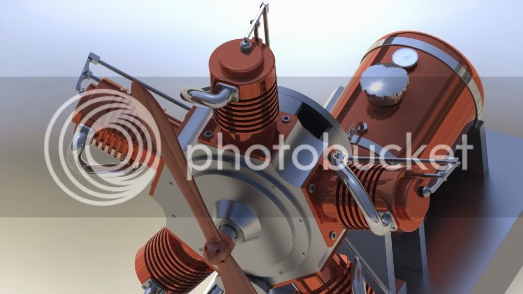
The model is intended to be a medium/large size "table-model" of a radial engine. The pistons are Ø50mm, that should say something about the size.
Materials used are: Copper, Aluminium 3003-H18 and some Stainless 316. (Fasteners not included)
The total mass is aprox 40Kg. The base-plate may be more massive than it needs to be.
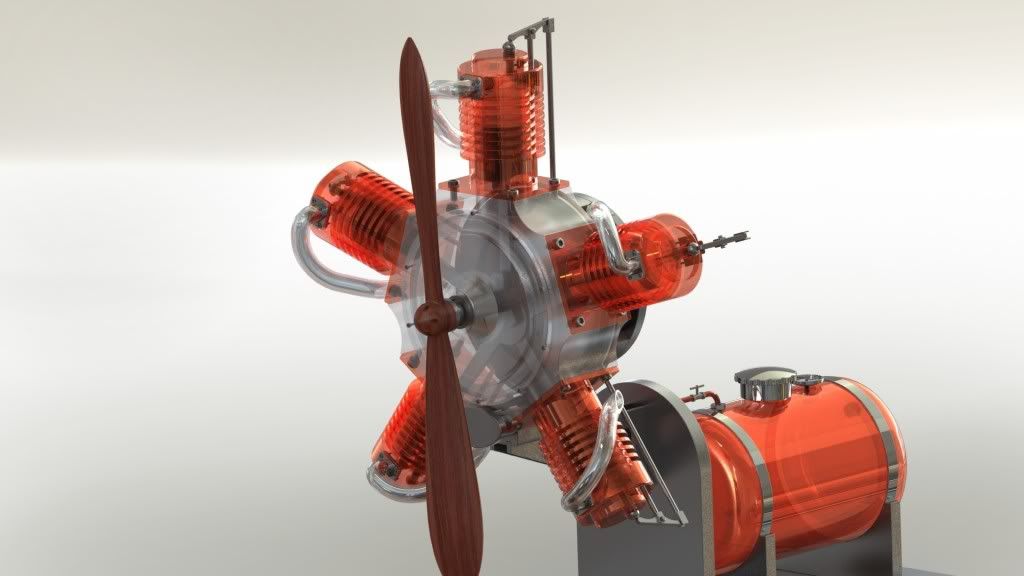
The propeller is here presented in rosewood, but was designed to be in aluminium and would serve as a counterweight.

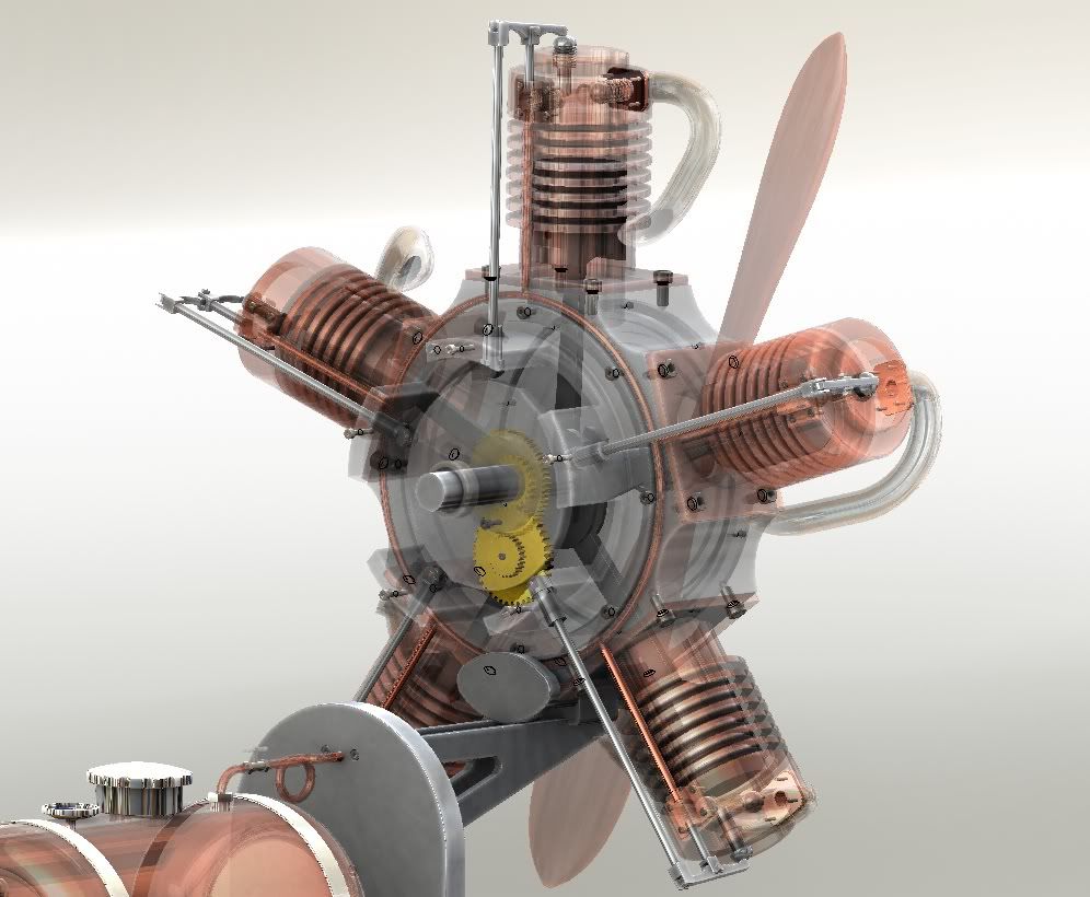
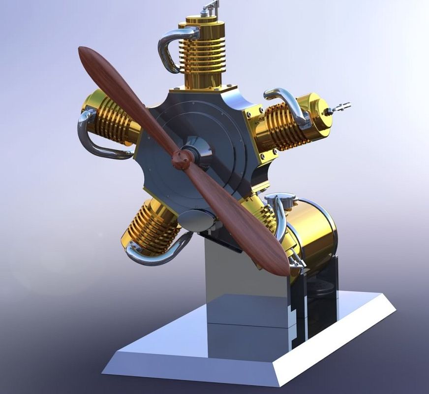
Here is the assembly of the 5-cylinder radial, I hope this thread will serve as inspiration to others as this forums has inspired me.
A2Cut.jpg

The variation of scenes and light may give different visual apperances.
A1Cut.jpg

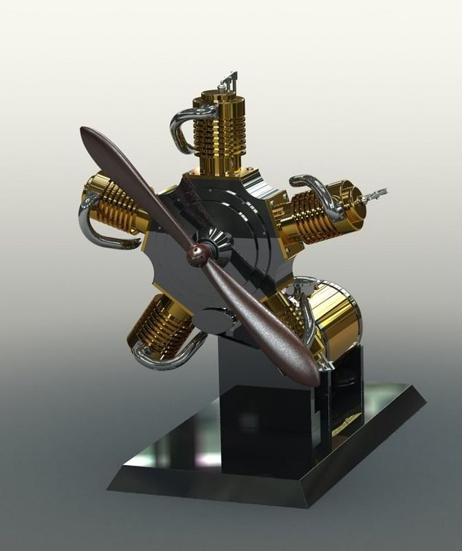
Brass and polished aluminium look.

A3.jpg

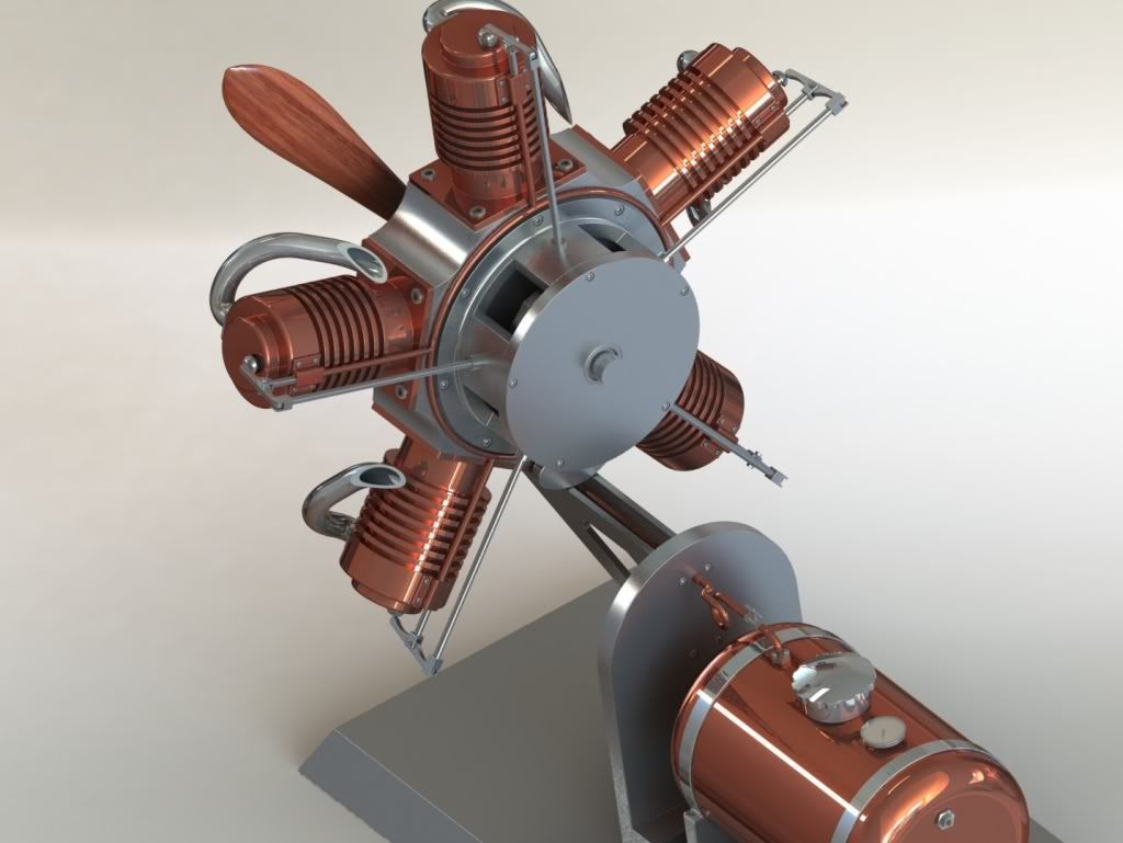
A bit more realistic copper and alu look.
A4Cut.jpg


A5Gamma.jpg

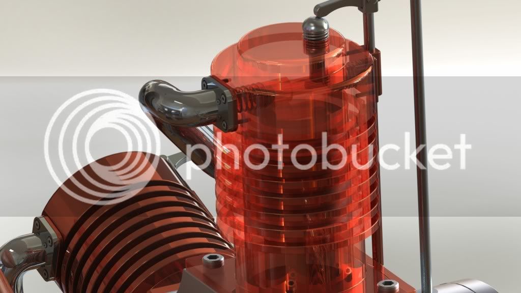
With cylinder transparency.

SectionCyl.jpg

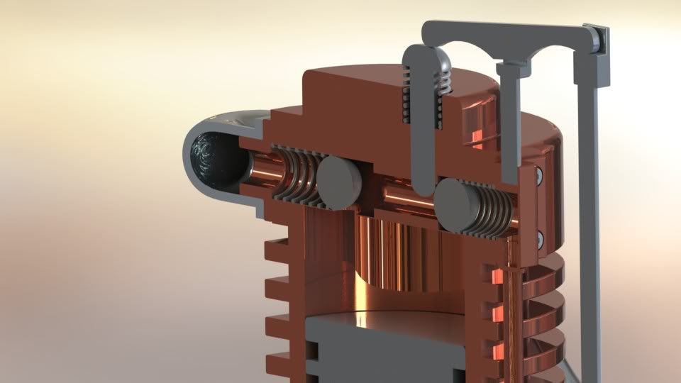
Section of cylinder. Shows ball-bearing exhaustvalve as seen in among others, the Halo engine.
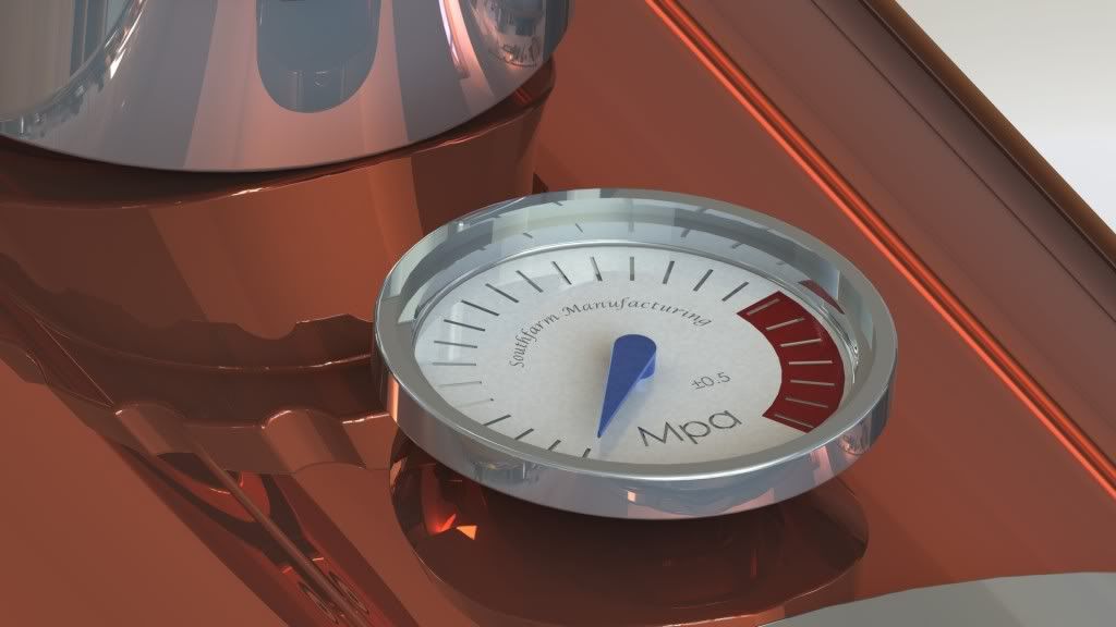
Gauge3-Maximum.jpg

Details
 
Hello Setarkos and welcome,

Beautiful work on your CAD project. You certainly deserve an A+ for your work. Did you complete the individual detail drawings of all of your engine's components? Although a bit large for most of us, I would think that many here would love to build a 1/4 or 1/2 scale version of your engine. Do you have access to a shop to build one? If so, I hope you also have access to an industrial compressor, it would be a monster. What is the diameter of the propeller?

What is your home country? Good luck with your studies, it sure looks like you have a pretty good grasp of 3D modeling.

Well done! Thanks for sharing your work.

Kind regards,
Mike
 
moconnor said:
Hello Setarkos and welcome,

Beautiful work on your CAD project. You certainly deserve an A+ for your work. Did you complete the individual detail drawings of all of your engine's components? Although a bit large for most of us, I would think that many here would love to build a 1/4 or 1/2 scale version of your engine. Do you have access to a shop to build one? If so, I hope you also have access to an industrial compressor, it would be a monster. What is the diameter of the propeller?

What is your home country? Good luck with your studies, it sure looks like you have a pretty good grasp of 3D modeling.

Well done! Thanks for sharing your work.

Kind regards,
Mike

Here Here :bow: :bow:

Have had a dabble into lights, luminance and surface finishes I have some appreciation of how much work went into producing those models.

Best Regards
Bob
 
Thank's for kind words.

The exam had to include three 2D-drawings as well, so I've got drawings for the cylinder, motorblock and one of the mounting-plates, more may come when i got the time. (If anyone would like to build this, i'm happy to share.)
Yes, I do have access to a CNC-shop where i teach manufacturing one night pr. week, allthough we are running a project where we are making a mini CNC-router, so I doubt there will be time to make this engine in the near future, but the machines we use are as made for the job.
[ame=http://www.youtube.com/watch?v=9uvMCCjq5dM]Okuma MultusB300[/ame]

What's impresses me the most is how many of you guys make these engines in manual lathes and mills. As a man of the cnc generation I concider that quite impressive.

The propeller is 500mm across, and since i have no experience with propper propeller/turbineblades it's probably not very efficient. :D
I'm from Norway.


Maryak said:
Here Here :bow: :bow:

Have had a dabble into lights, luminance and surface finishes I have some appreciation of how much work went into producing those models.

Best Regards
Bob
Well, the program itself and a good graphics card does most of the work. For rendering i use a integrated SolidWorks application called PhotoView360.

/S


Ps. Some more pics.

Transp2.jpg


Transp1.jpg

(I know, the timing gears may not be quite right! :) )
 
That is a very nice looking model.

Can you explain the valve? Ive looked at the section model, and I see that the rocker arm has a short push rod that can move one of the balls, but I don't see the use of the other ball, and I don't understand the porting.

 
That is an excellent CAD model.....you would pass my Solid Works class with flying colors!

Which program did you create the model in?

My journey into this hobby started with modeling various engines in Solid Works and creating kinematic animations. Then one day I decided to actually make one and have been hooked ever since.

One of the greatest compliments you can give a model engine builder is to model their engine in 3D....from a CAD guy's perspective anyway.

Great job!!!!!!!!!!

:bow:
Chris
 
That is very nicely done! Some of the other engineers where I work do some renderings with our solidworks models, and I can appreciate the artistic talent that has to be coupled to the technical talent to make images like that. It is something I struggle with.
 
If I understand the model correctly, the rocker arm controls the input port, and it appears that the exhaust is a poppet valve.
 
Beautiful drawings! Thank you for acknowledging my valve design. You've certainly applied it to a lovely engine design.

If I may explain the valve operation, the intake is operated by the push rod which moves the intake ball valve aside to admit air. The incoming air pushes the exhaust ball valve to one side which opens up the inlet to the cylinder to the incoming air and simultaneously seals off the exhaust port. When the inlet valve is closed, spring pressure returns the exhaust ball valve back to the other side connecting the port to the cylinder to the exhaust port.

This design, by the way, is freely available for anyone to use.

Chuck
 
Very nice work!!! I create literally thousands of Solidworks parts, assemblies, and drawings as part of my "regular job", but they are nowhere near as pretty as yours. Of course, my customers care a great deal about functionality, but they get pretty ugly at the concept of "pretty". (If they have to pay for it.) I keep all of the photo rendering turned off as I find it a distraction while working, but it can certainly create some beautifull models as your posts so aptly show.----Brian
 
Setarkos-

That is some very nice modeling.
I don't have the rendering part of Solidworks, since that is an expensive option, and can be time consuming to use.

The photo renderings are very nice to look at.

Some have said my models are "Just a pretty picture", and while I would certainly agree with that statement (ie: a pretty model is not the same as say the HMEM project of the month), I think there is great value in modeling from a design aspect, and if you get interested in the design, then chances are you will want to learn how to machine also, so I think the modeling can eventually lead to some good machining and model making.

Modeling is also a great way to test various approaches to machining the parts, as well as whether the parts will fit together in an assembly. It is much better to find all the "gotchas" before starting to make parts. Do the parts of the assembly rotate without binding or without interferences with other parts?

Things to keep in mind when designing using a modeling program:
1. Are the minimum material thicknesses sufficient? (everything looks good in a model, but sometimes thickness turn out to be too thin or thick when you see them in the real world).
2. Are the fasteners actual size? Fasteners should be drawn to actual size for the size of model you intend to make. Will you make custom/scaled fasteners, or use standard fasteners?
3. Is the model "buildable"?, ie: do the shapes/contours of the model match existing bit sizes and radius?
4. Does the model make maximum use of standard material sizes? For free-lance modeling, you can save a lot of material if you design the engine using the nearest standard/stock material dimensions, or stay close to standard material sizes.

Just a few thoughts.
Very nice modeling.
 
vascon2196 said:
That is an excellent CAD model.....you would pass my Solid Works class with flying colors!

Which program did you create the model in?

My journey into this hobby started with modelling various engines in Solid Works and creating kinematic animations. Then one day I decided to actually make one and have been hooked ever since.

One of the greatest compliments you can give a model engine builder is to model their engine in 3D....from a CAD guy's perspective anyway.

Great job!!!!!!!!!!

:bow:
Chris
Thanks! The professor and the sensor is going over the design this week, so it will be interesting to see if they are of the same opinion. :) I've used SolidWorks 2011/2012 for this model.
I can relate to what you are saying, even if I know that a model will work, I still find much pleasure in making the motions work properly.


UNIcastings said:
Setarkos-

That is some very nice modeling.
I don't have the rendering part of Solidworks, since that is an expensive option, and can be time consuming to use.

The photo renderings are very nice to look at.

Some have said my models are "Just a pretty picture", and while I would certainly agree with that statement (ie: a pretty model is not the same as say the HMEM project of the month), I think there is great value in modeling from a design aspect, and if you get interested in the design, then chances are you will want to learn how to machine also, so I think the modeling can eventually lead to some good machining and model making.

Modeling is also a great way to test various approaches to machining the parts, as well as whether the parts will fit together in an assembly. It is much better to find all the "gotchas" before starting to make parts. Do the parts of the assembly rotate without binding or without interferences with other parts?

Things to keep in mind when designing using a modeling program:
1. Are the minimum material thicknesses sufficient? (everything looks good in a model, but sometimes thickness turn out to be too thin or thick when you see them in the real world).
2. Are the fasteners actual size? Fasteners should be drawn to actual size for the size of model you intend to make. Will you make custom/scaled fasteners, or use standard fasteners?
3. Is the model "buildable"?, ie: do the shapes/contours of the model match existing bit sizes and radius?
4. Does the model make maximum use of standard material sizes? For free-lance modeling, you can save a lot of material if you design the engine using the nearest standard/stock material dimensions, or stay close to standard material sizes.

Just a few thoughts.
Very nice modeling.

I really appreciate your advice! The rendering tool is great for presentations, it can really show the beauty of a otherwise dull 3D model. As you mention it is very time consuming, on Hd resolution it might take an hour or two for a complex image, but it makes me so happy to watch the results that this is soon forgotten. (A smaller image doesn't take more than minutes)

I went the other way. It all started with mechanical education and a apprenticeship where I worked with cnc and semi-manual manufacturing. Trying to decode all the crappy drawings we revived from engineers without experience gave me the idea to try it for myself and spent many hours playing with the program without further training.
During the SolidWorks class I just finished we have learned not only to design, but to design a smart model winch would be possible to understand for a colleague.

All the fasteners in this assembly is created with the smart fastener feature after ISO-standard, it's mostly M2 to M5 hexagonal bolts(Umbraco).
Contours are made as simple as possible, but still safeguard a nice visual impression. I've used two types of fillets, machinable and "Debur-fillets". That said, seeing what people do with manual mills here, it looks like nothing is impossible. Therefore I should at-least be able to duplicate it with a 5-axis machine.

The model rotates as it's supposed to, except for the rocker-cam, the program does some miscalculations here. I'll try to get a video up, but then we are talking rendering time! Even for a low resolution movie clip.

@RonGinger:
The valve works as cfellows explained, I used hies sketches as guide. It took me a while to understand this valve-design form looking at pictures of the Halo engine, but when I saw these drawings it all became clear.
(Original Thread
BallValveClosed.png

BallValveOpen.png
 
[ame]http://www.youtube.com/watch?v=oKxstwtfQUI[/ame]
Short video of the valve.
 

Very nice renderings and animation Setarkos. Beautiful Job!
 
Got an A on this one, I think I'm to thank this forum for that.
Thank you all for inspiration and great tips!
 
S-

Great simulation.
It is really nice to be able to see an engine run before you try and build it.

Great job on the models.
I can't wait to see the engines you build.
 
Back
Top