Building the Trevithick engine

Home Model Engine Machinist Forum

Help Support Home Model Engine Machinist Forum:

This site may earn a commission from merchant affiliate links, including eBay, Amazon, and others.
Hi Brian,
having made a few assumptions regarding wheel diameter etc, I calculate that at the nominal 5 MPH quoted as a typical speed at Penydarren ,
the engine was turning at approximately 64 RPM.
How do you think this would relate to your model?
Hope the greater mass of the new flywheel gets you over the hump with a continuously running engine.
Cheers,
Fred
 
-Big changes with the heavier flywheel. The flywheel is rocking back and forth like crazy between top dead center and bottom dead center under air pressure. This is very promising. Based on what it's doing now, it should just require some adjusting of the valve actuators on the slide bar. I have just blown an internal hose and have to tear things down to reconnect it. Is there any kind of liquid glue that I can permanently glue the neoprene hoses to the brass or steel tubes on the 4 way valve ? I do have some small spring wire clips from the hobby shop, but at higher air pressure the hoses keep blowing off. Crazy glue sets up so quickly that I wouldn't have a chance to put some glue on the steel tubes and then slip the neoprene hoses over them. Is there something like a "delayed action" super-glue?
 
I learned three new things today. #1--There is a type of crazy glue that doesn't dry instantly--it gives you about 15 seconds between when it is applied and when it dries. This is enough time to coat a hose barb (actually a piece of 0.185" diameter brass tube) and slip a neoprene hose over it before it becomes absolutely immoveable.---If you're quick!!
---#2--If you have a bunch of air connections inside something else that requires an hours work to take it apart, then never, ever, ever use neoprene tubing pushed onto metal tubes for connections.--Make them from metal tubing and solder them in place.
---#3---Engines which have wheels on them are as suicide prone as lemmings, which jump off cliffs into the sea. I've probably grabbed this damn thing out of the air half a dozen times today when it jumped off my desk. I haven't moved so fast since my wedding night.
 
After a full day of fixing disconnected tubing and taking things apart and then putting the parts all back together again, it was time for some analysis as to what was happening. Right now, as things set, the valve is set so that it is fully opened at the end of the piston stroke in either direction. Now, in a perfect world, where the flywheel really was doing it's job, the inertia of the flywheel should carry the crankshaft "over the top" before the piston begins to travel in the opposite direction. Since the flywheel is bouncing back and forth between the top and bottom dead center, the conclusion is that the valve is being actuated just a tiny bit too soon. If the opening was delayed for another millisecond, the crankshaft would have that space of time to get "over the hump" and make complete revolutions rather than bouncing back and forth thru partial rotations. So yes Charles, I do agree with what you are saying and what you show in your diagram. With everything "as designed", I can adjust the sliders so that the valves begin to open a bit later in the cycle, which in theory mean they would close a bit later in the cycle. That would be a "best case" scenario. If that doesn't work, then as Charles suggested, shortening the radius arm on the valve would allow the valves to operate closer to the end of the piston stroke and hopefully allow the flywheel to get "over the hump" before travelling back in the opposite direction. I have the capacity with my current design to shorten up the radius arm with no other changes.
 
Bah!! Humbug!!--The easy fix (repositioning the valve actuators) didn't work. I have never had an engine so close to running that didn't actually take off and run. I can see a number of things which I could do to fix this, but they are all progressively more and more difficult. The next easiest fix is to shorten the radius arm on the valve. Of course this will make for an extended cantilever on the sliding brass actuator. I have a small (3mm) ball bearing that I think I can work into the equation to take a bit more friction out of the valve action. Oh well, thanks to Covid there is damn all else to do anyways.
 

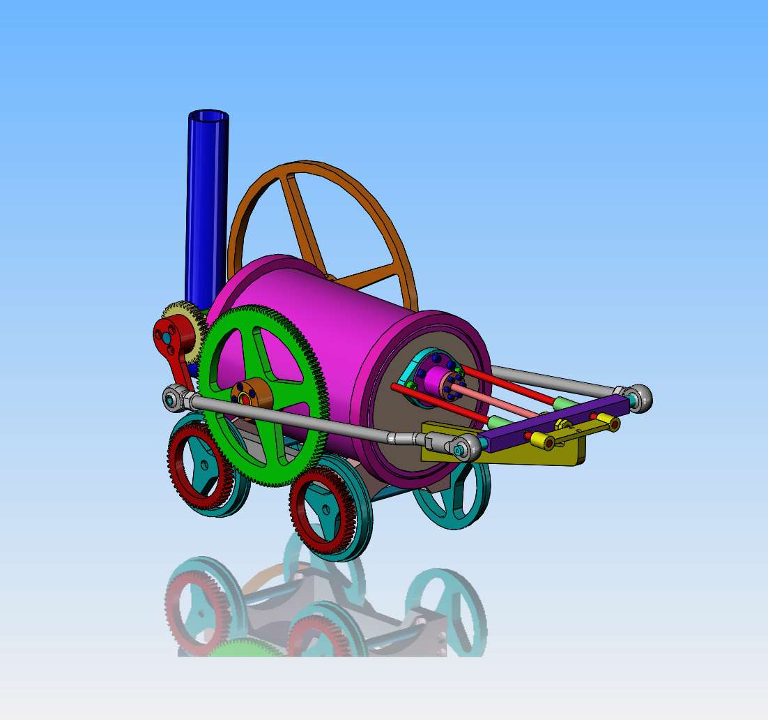
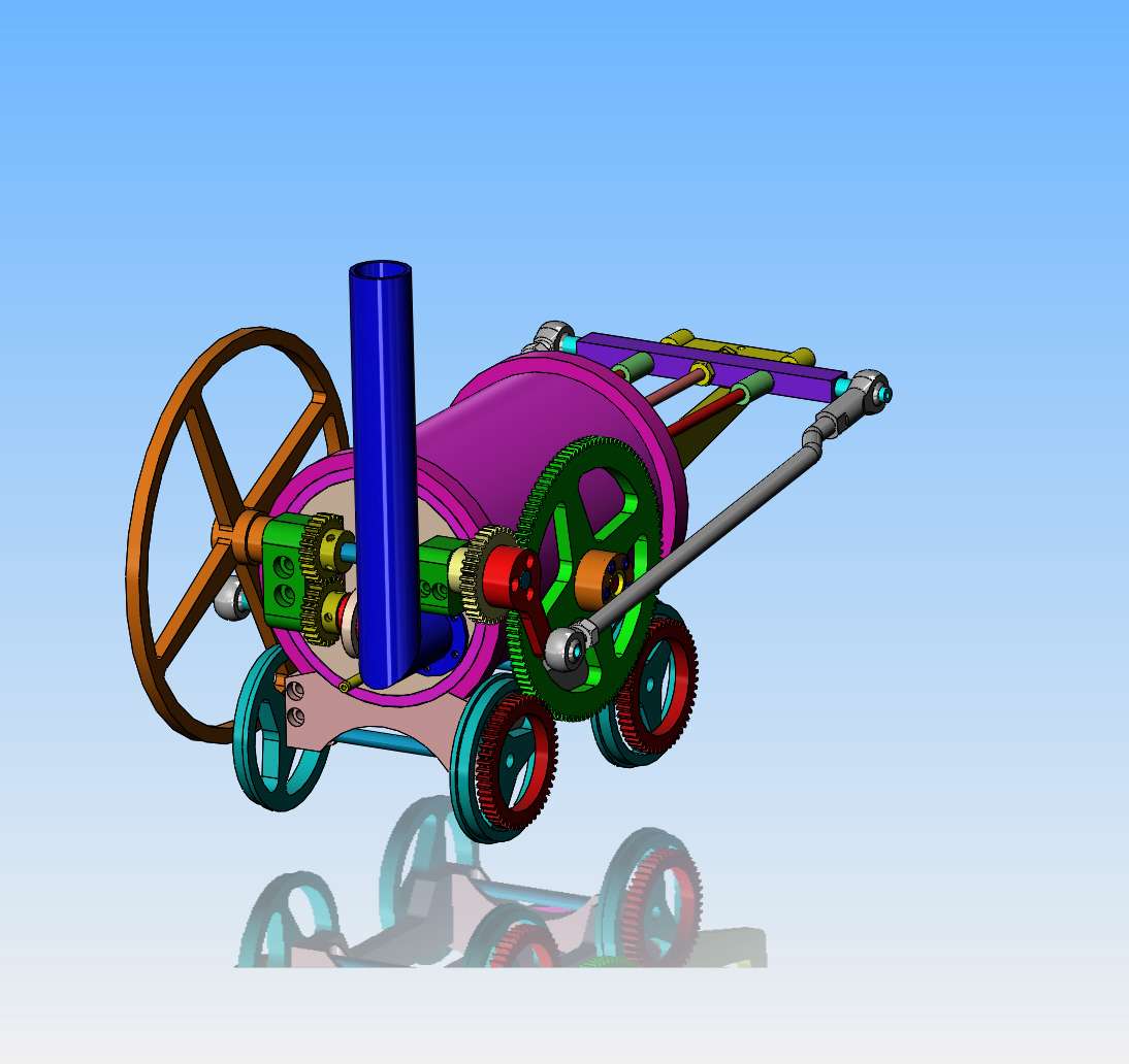
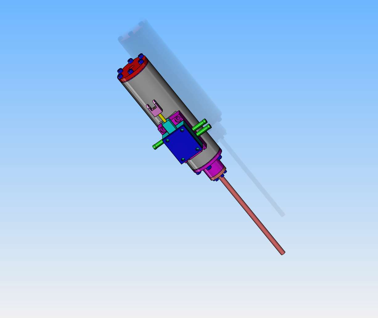
This is my Trevithick engine doing something I haven't seen before. It has a unique 4 way valve mounted on top of the boiler, and the valve swings back and forth under the influence of the sliders which contact the valve arm. I don't have things set up quite right yet, so the engine is "stuttering"---The valve is being reversed before the piston gets far enough in it's linear travel to get the crankshaft over dead center and complete a full revolution. This is not what I am ultimately aiming for, but I hope that with some adjustment to the sliders I can coax it into full revolutions.---Brian
 
Brian, The problem as I see it is the valve is fully in the reverse position before the cylinder reaches the end of its stroke.

It needs some form of over centre / sprung / cam action - such that at the end of stroke the valve is amidships and then at the last possible moment goes over centre and is flipped into full astern by the cam / spring etc. action.

Something like this...
camvalve.jpg

Just a suggestion to help you get your creative juices flowing.

The crank throw pushes it to dead centre / closed - the next say 5° - the valve is still closed but the cam action goes into freefall and the valve snaps the other way just at the end of the cylinders' stroke.

Just the first thing that went through my mind, I'm sure you can come up with something more elegant / simple.

Regards, Ken
 
I've tried all of the tricks in the "Rupnow Magic Hat" and I am not able to get this thing to run using the 4 way valve. It is one of those engines that wants to run so badly that you can almost taste it, but it isn't happening. I have tried all of the different settings that I can think of, and have pinched my fingers so badly that I cried like a baby, but this just isn't going to run for me. This is not to say that the project is abandoned--Just that it isn't going to run with this 4 way valve. I can salvage most of the parts and make a Trevithick engine that runs with a more conventional slide valve. I hate to admit that I haven't been able to get this to work, but I have tried everything I can think of. Weirdly enough, I can make the model look more like the original Trevithick by using a conventional slide-valve than I could of if the 4 way valve had done the job.
i8oJXi.jpg
 
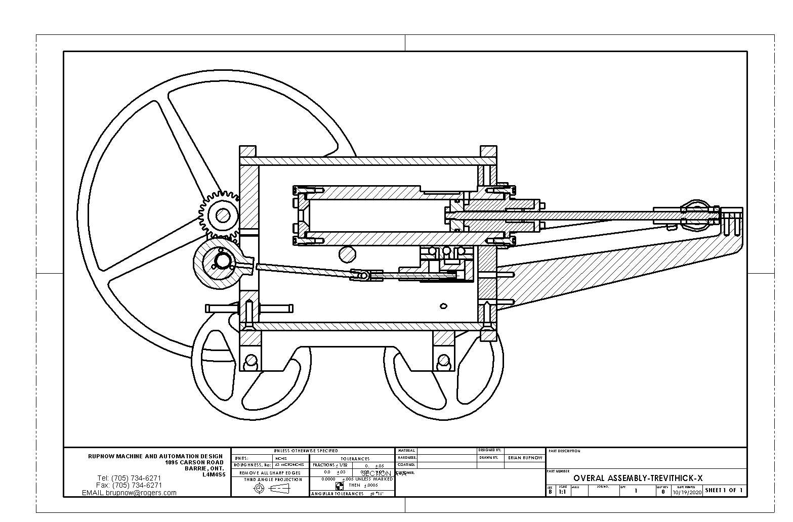
Boys, we're going to start down a new path today. I'm very disappointed that I didn't get this engine to run with the 4 way valve and I really, truly thought that I would. Ah well, so much for unbridled optimism. The change of course is going to involve a more conventional steam slide valve on the cylinder. Due to restrictions based on everything having to fit inside the boiler, I am going to have to gear the crankshaft to a "camshaft" and mount the eccentric strap and eccentric on the camshaft. (it will revolve at the same speed as the crankshaft.) This means that the steam-chest will hang from the underside of the existing 3/4" diameter x 3" stroke cylinder, similar to the way it did on the Stephenson's Rocket. I will be getting rid of all of the exterior valve control rods and guides, and the rings with built in rod guides will revert back to being just simple rings around the ends of the boiler. The only visible difference is going to be at the smoke-stack end of the engine, where it will be possible to see the extra set of gears to operate the cam shaft, and different method of mounting the crankshaft and cam shaft. If this sounds like a lot of extra work, well, yes, it will be.-However, it's Covid time. Can't visit friends, can't go out for entertainment, can't even see my grandchildren nor take out good-wife for a restaurant meal. I'm just happy to have something fun to do!!!
UtY65M.jpg

TTqvnN.jpg
 
Ken 1--thank you for your input. I know what your drawing is showing, I have messed around with "toggles" before. Unfortunately there is no good way to add toggles to the existing Trevithick engine valve actuators, and as you see in the above post I have a different idea which I will now pursue.---Brian
 
Just finished the big three hour "clean-up, slick-up, put all my tools away in the correct place" dance. I try and put my tools away as I use them, but when I get into the final lap of building something I get so excited that nothing gets put away properly. When I walk into my little machine shop and the floor "crunches", I know that it's about time for a sweeping and vacuuming. My apologies to everyone who hoped to see this run with the 4 way valve.---I did too. My apologies to anyone who I may have snapped or snarled at on the forums. I'm not normally like that. This project hasn't stopped. Very little of my work will be lost, even the cylinder will remain the same. The 4 way valve gets tossed, and I gain a cam shaft and conventional slide valve to control the cylinder. Don't go away please. There is more to come, and I promise, it will be interesting.---Brian
 
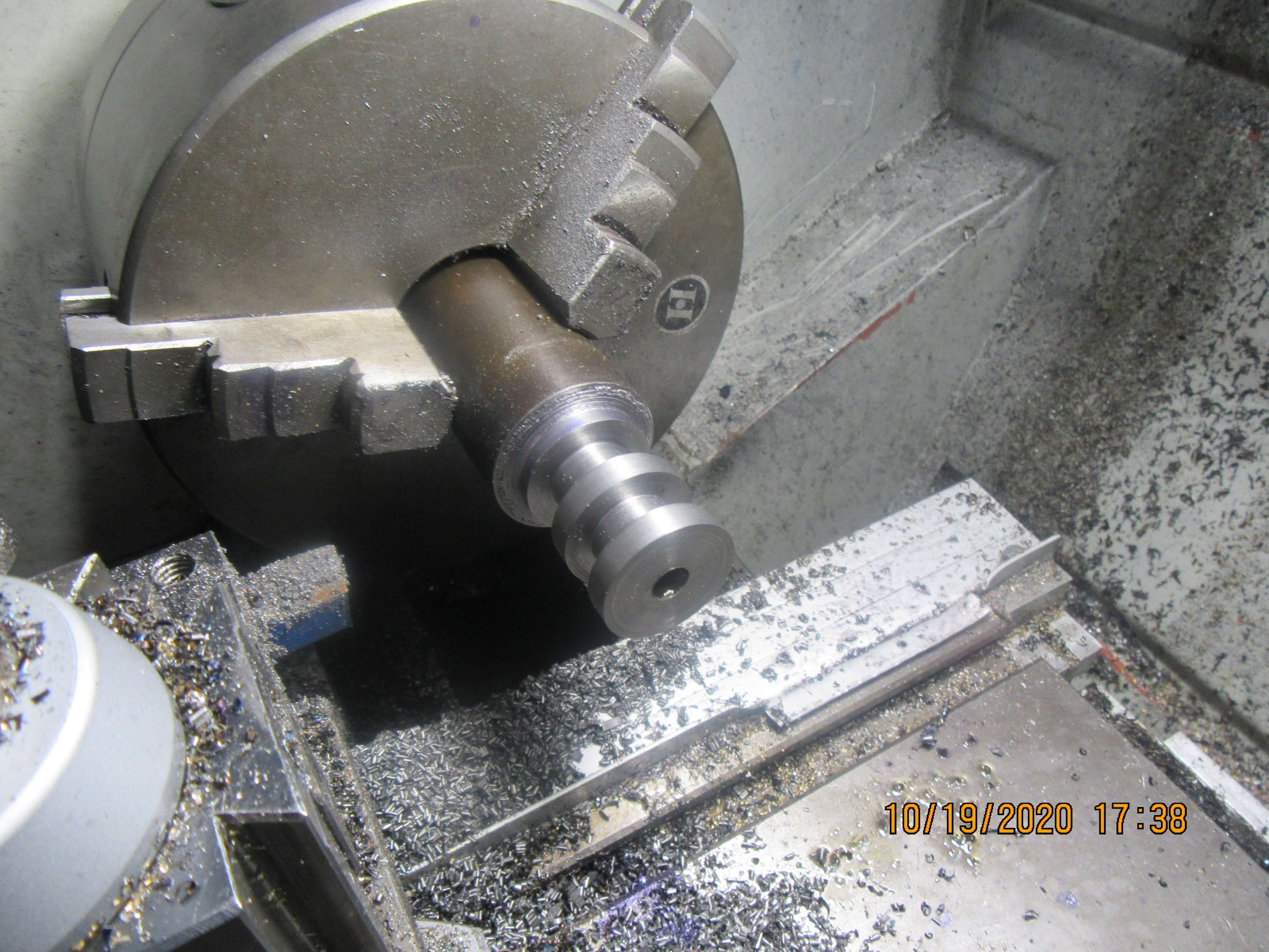
Two 25 tooth gear blanks turned and that's all she wrote for today. O.D. and hubs are turned to size from 1144 stress proof steel. Center hole has been drilled and reamed to 5/16" diameter. Next time you see them they will have teeth cut and be mounted in place.
DJ0WDn.jpg
 
Brian, I like your solution - but since you went to all the trouble of making the rotary valve and linkages etc. why not just leave them in place as cosmetic.

Regards - Ken
 
Doing something a bit new and different. Normally, when steam-chests are used with a cylinder they are either both machined as one part from the same piece of material or soldered together, and all of the steam passages are internal inside the walls of the cylinder. In my case, I am retrofitting a steam-chest onto a cylinder which was previously operated by my 4 way valve. The steam lines are going to be external to the cylinder. I will solder brass "hose barbs" into the steam-chest and run flexible neoprene lines from the steam-chest to the cylinder ports. ( I know I cautioned against doing that but needs must.) I have never seen that done, but I can't think of any reason that it won't work.
47oWRt.jpg
 

Latest posts

Back
Top