Brian, you skinned that cat well, neat idea, interesting, you good and thanks for sharing, Joe
You are using an out of date browser. It may not display this or other websites correctly.
You should upgrade or use an alternative browser.
You should upgrade or use an alternative browser.
Building the Trevithick engine
- Thread starter Brian Rupnow
- Start date

Help Support Home Model Engine Machinist Forum:
This site may earn a commission from merchant affiliate
links, including eBay, Amazon, and others.
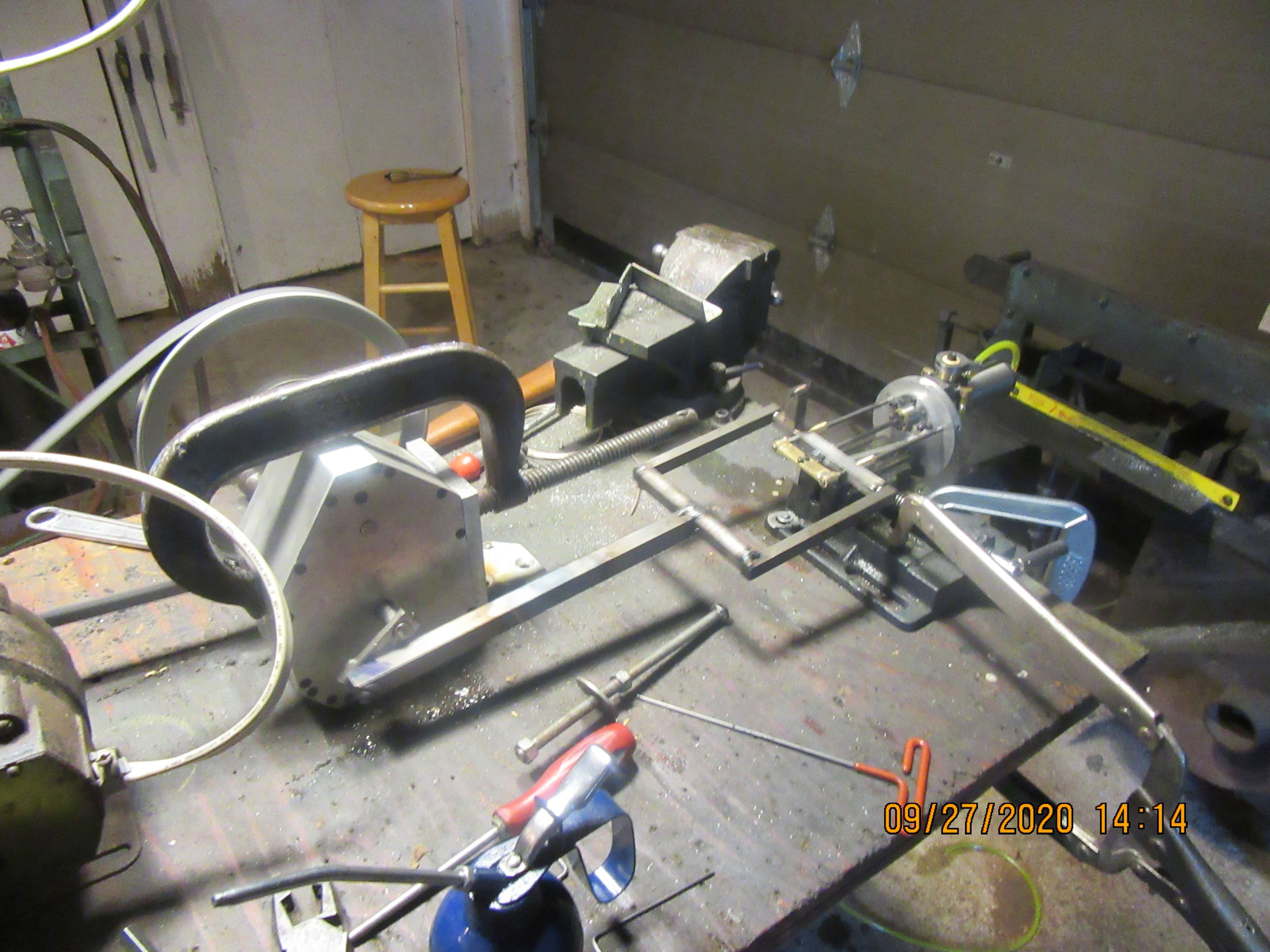
Here is a fun little video of "running in' the cross-head and cross-head guides to make them operate smoothly without binding.
Hello Brian, looking great and will be another Great Rupnow model to display. Once you have run in the mechanisms, I would suggests if you restricted the air flow into the cylinder with an adjustable valve, the movement would be slower and smoother toward the end of the stroke but would not reduce the torque. Cheers. john
Me too ,sorry to say. You do great work.Brian i am also guilty of lurking and not saying anything. Just enjoying each ride. Please don't stop.
Gary
Ron
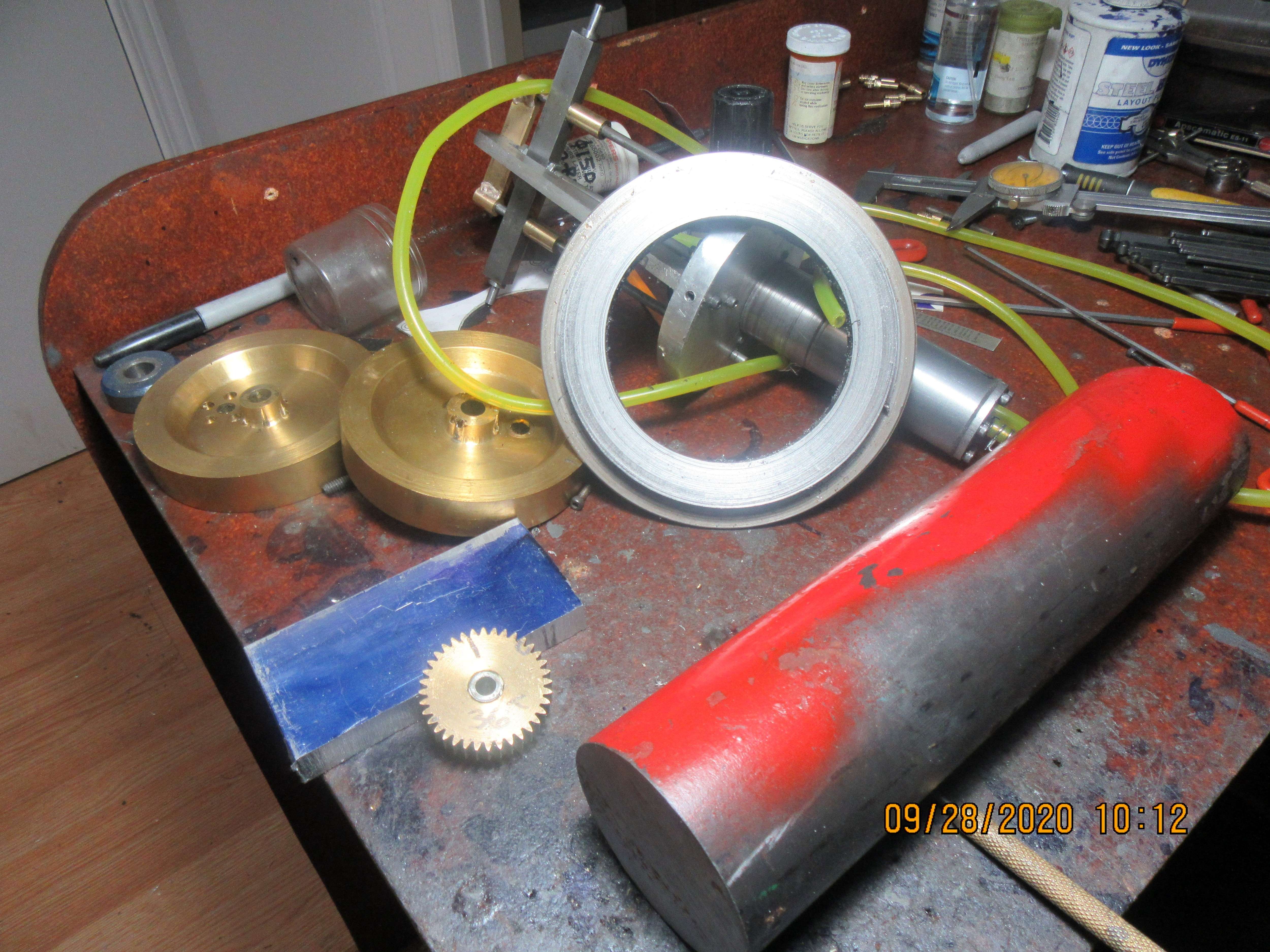
This morning I went searching about for material to make all of my gears. Okay--Good news is that I already have a 36 tooth gear left over from some project, that can be repurposed. It is the gear which sets up on the same shaft as the flywheel, and by all rights should be made of steel. Since this is only a demonstration engine that will see very few miles, I will use this gear anyways. I hunted up two bronze flywheels from the old Rupnow Hit and Miss engine, which has been scrapped and caniballized, but they aren't really of size that I can use. I found a really big round piece of mild steel that was a cut-off from something else I built, which will do to get the 108 tooth gear from.--And---I have a big long piece of 2 1/2" diameter hot-rolled which will work fine for the 50 tooth gears that attach to the wheels. In other news--Yesterday, on my "fat mans walk" I lost a pair of bifocal glasses. As soon as wife and I got home, I realized that I didn't have them, so we went back and walked the trail again looking for them, but no luck. I have put up a sign at each end of the trail explaining what I had lost and my phone number, in case someone else found them.--If not, I'm out $300. That would have bought me a lot of material for my hobby.

Last edited:
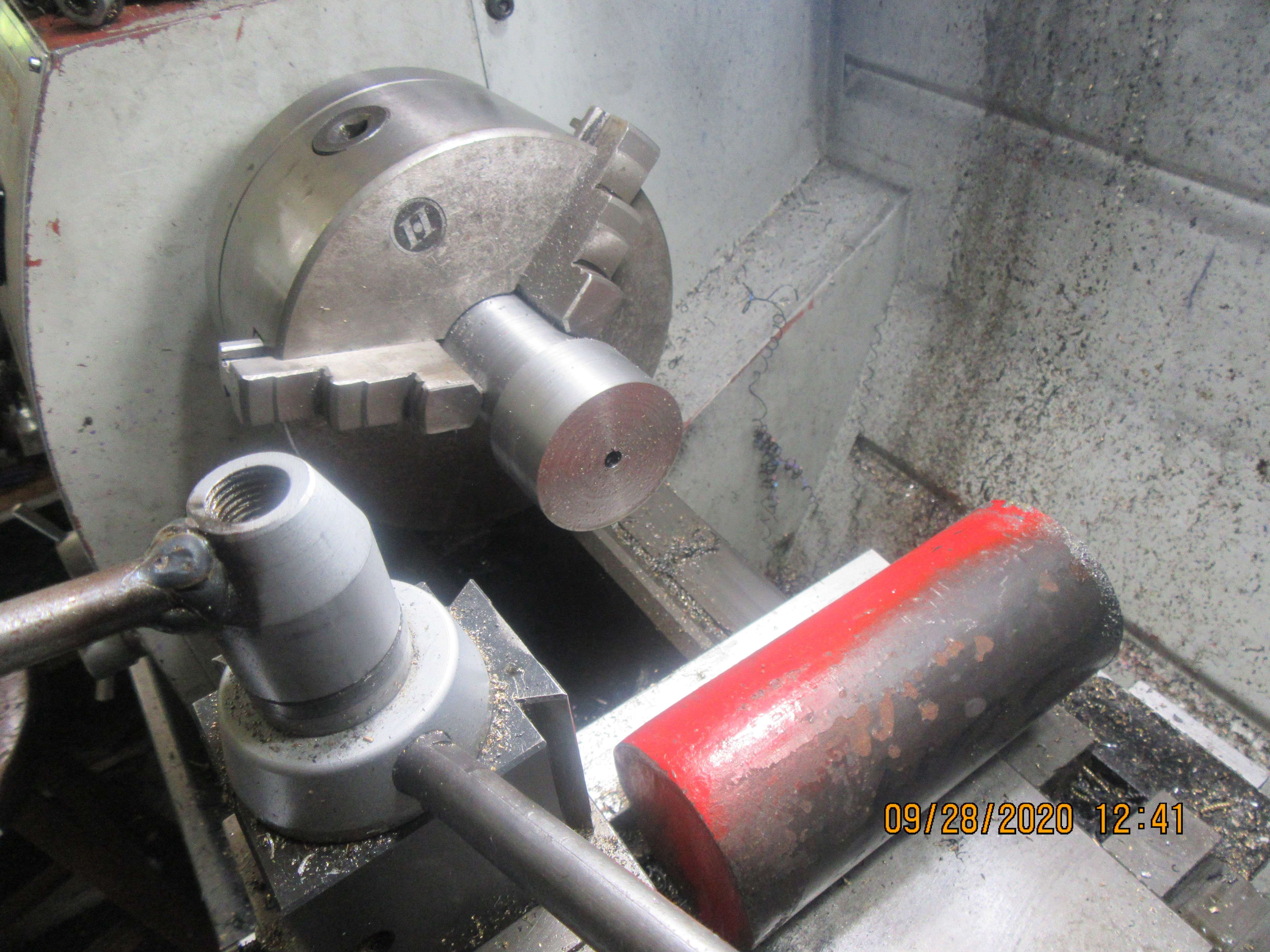
Okay---Here we go---hang on. The 2 1/2" round hotrolled has been cut off, to a sufficient length to give me two or three gears and a handle to hold in my rotary table chuck. The large outer diameter has been turned to what the actual outside diameter of the gear will be. The smaller diameter is turned to a diameter that is smaller than the root diameter of the gear teeth to be cut, and long enough so that I don't run the gear cutter into the hardened chuck jaws. That will immediately ruin a cutter. Don't ask how I know this. The center has been drilled and reamed to 1/4", which is the diameter of the axles on my Trevithick.

I'm here, I'm lurking as usual. I don't have anything to contribute, but I do enjoy the way attach an issue. Keep up the good work. LorenJoe--thank you for stopping by and leaving a comment. I don't get many people stopping by to say Hi anymore.---Brian

$39.99
$49.99
Sunnytech Low Temperature Stirling Engine Motor Steam Heat Education Model Toy Kit For mechanical skills (LT001)
stirlingtechonline

$89.99
Outdoor Wood Boiler Water Treatment Rust Inhibitor- AmTech 300 & Test Kit
Alternative Heating & Supplies

$34.74
$49.99
Becker CAD 12 3D - professional CAD software for 2D + 3D design and modelling - for 3 PCs - 100% compatible with AutoCAD
momox Shop
![DreamPlan Home Design and Landscaping Software Free for Windows [PC Download]](https://m.media-amazon.com/images/I/51kvZH2dVLL._SL500_.jpg)
$0.00
DreamPlan Home Design and Landscaping Software Free for Windows [PC Download]
Amazon.com Services LLC

$599.00
$699.00
FoxAlien Masuter Pro CNC Router Machine, Upgraded 3-Axis Engraving All-Metal Milling Machine for Wood Acrylic MDF Nylon Carving Cutting
FoxAlien Official

$99.99
AHS Outdoor Wood Boiler Yearly Maintenance Kit with Water Treatment - ProTech 300 & Test Kit
Alternative Heating & Supplies
Thanks Loren---I see all of the 'likes" you have been awarding my thread.
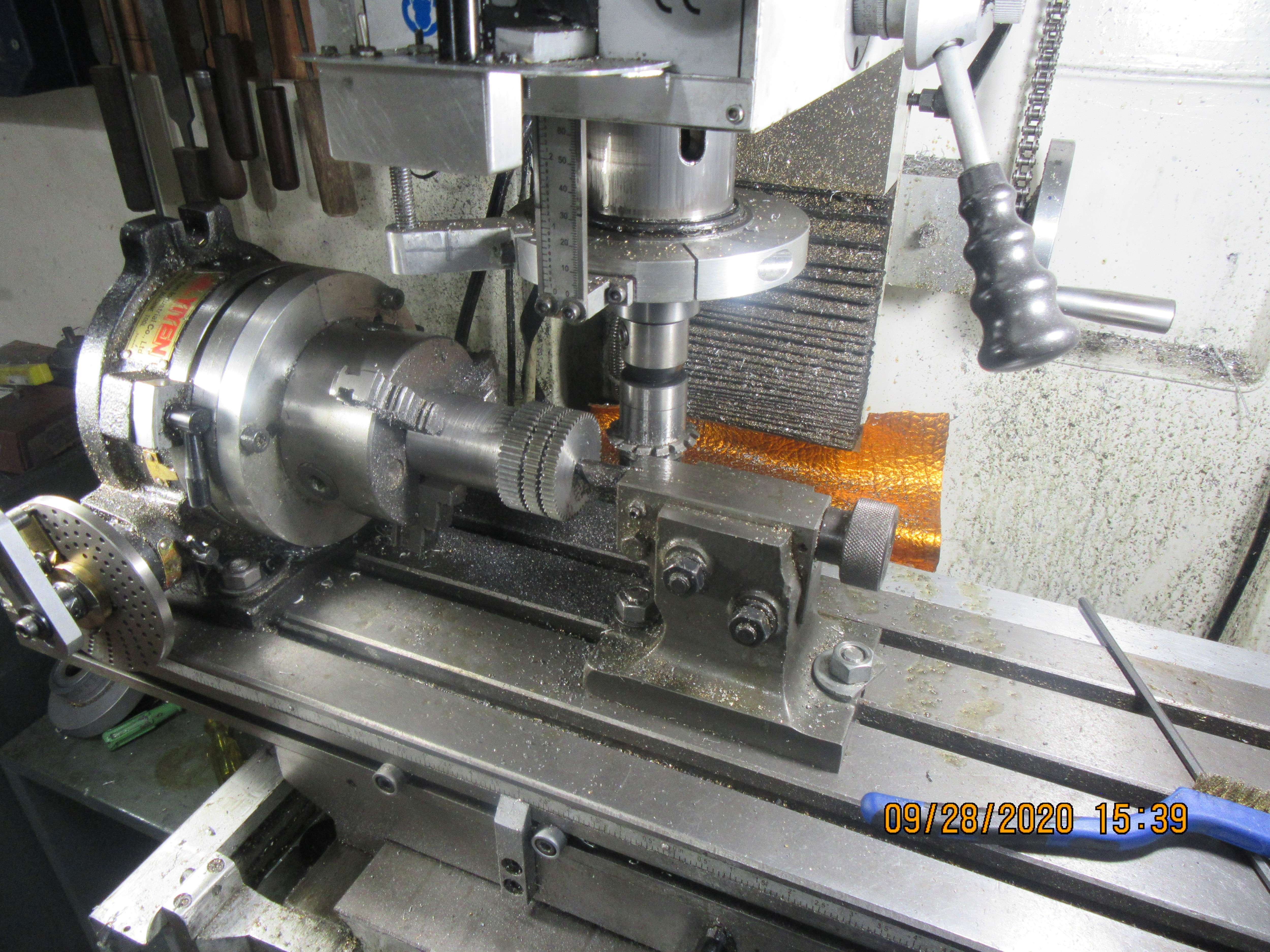
I've just finished cutting the 50 tooth gears. A couple of things here worth mentioning. Any time I cut gears, I try and make the gear blank a bit longer than necessary. That way I get the two gears I wanted, plus a "free-bee" that I can use on some future machine. I use the tailstock support, because the material is sticking out quite a long ways from the chuck. At the very front of the table, you will see two "table stops" that I set before I started cutting, so I can't run the cutter into the hardened chuck jaws nor into the tailstock support. Lastly, you can see that I used my cut-off tool in the lathe before I started cutting the gears. I cut just deep enough to be lower than the root diameter of the gear teeth. This avoids pulling burrs on all of the gear teeth, which happens if you wait until after the teeth are cut to part off the individual gears.
.
I've just finished cutting the 50 tooth gears. A couple of things here worth mentioning. Any time I cut gears, I try and make the gear blank a bit longer than necessary. That way I get the two gears I wanted, plus a "free-bee" that I can use on some future machine. I use the tailstock support, because the material is sticking out quite a long ways from the chuck. At the very front of the table, you will see two "table stops" that I set before I started cutting, so I can't run the cutter into the hardened chuck jaws nor into the tailstock support. Lastly, you can see that I used my cut-off tool in the lathe before I started cutting the gears. I cut just deep enough to be lower than the root diameter of the gear teeth. This avoids pulling burrs on all of the gear teeth, which happens if you wait until after the teeth are cut to part off the individual gears.

.
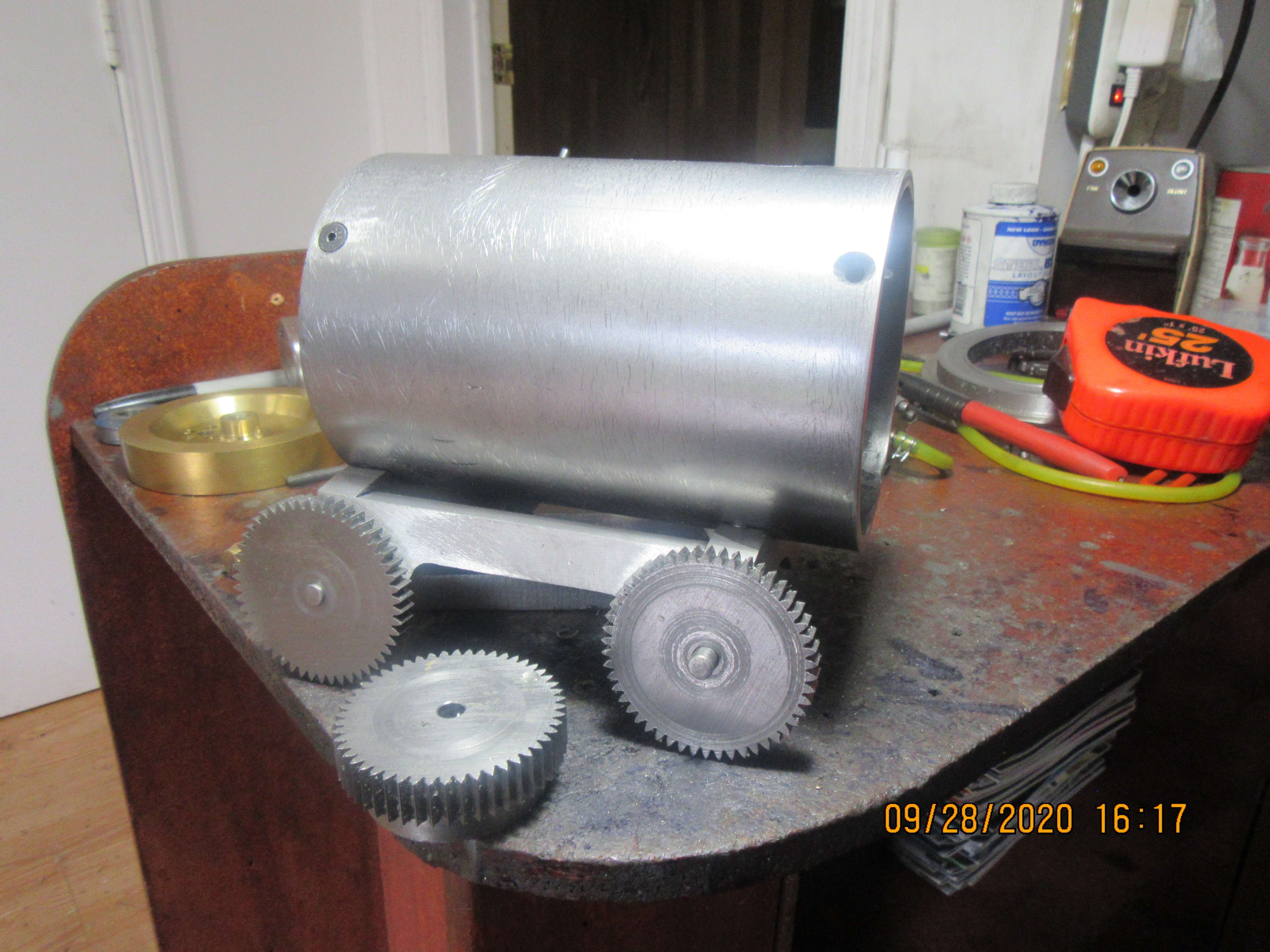
This is what I end up with. Two 50 tooth gears to go on the Trevithick, and one spare to be used on some future project. The centers will eventually be removed from these two gears and they will be attached to the wheels as shown on the 3D model, but for now they can stay mounted on the axles until I finish all the gears and see that they mesh properly.

I too, am here, lurking as usual. Some of the simplest ideas can be the most useful and productive.
- Extra length of the blank and table stops to avoid a potential crash
- Parting tool cuts before cutting the teeth the minimize deburring work
- A freebie when you are all done...
Thanks for expending the effort to document your work and methods.
Larry In New Jersey
- Extra length of the blank and table stops to avoid a potential crash
- Parting tool cuts before cutting the teeth the minimize deburring work
- A freebie when you are all done...
Thanks for expending the effort to document your work and methods.
Larry In New Jersey
Hi Larry. Nice to hear from you. Every once in a while I let some jewel of machine shop wisdom loose on here, and almost every day I learns something new from the forums myself.---Brian
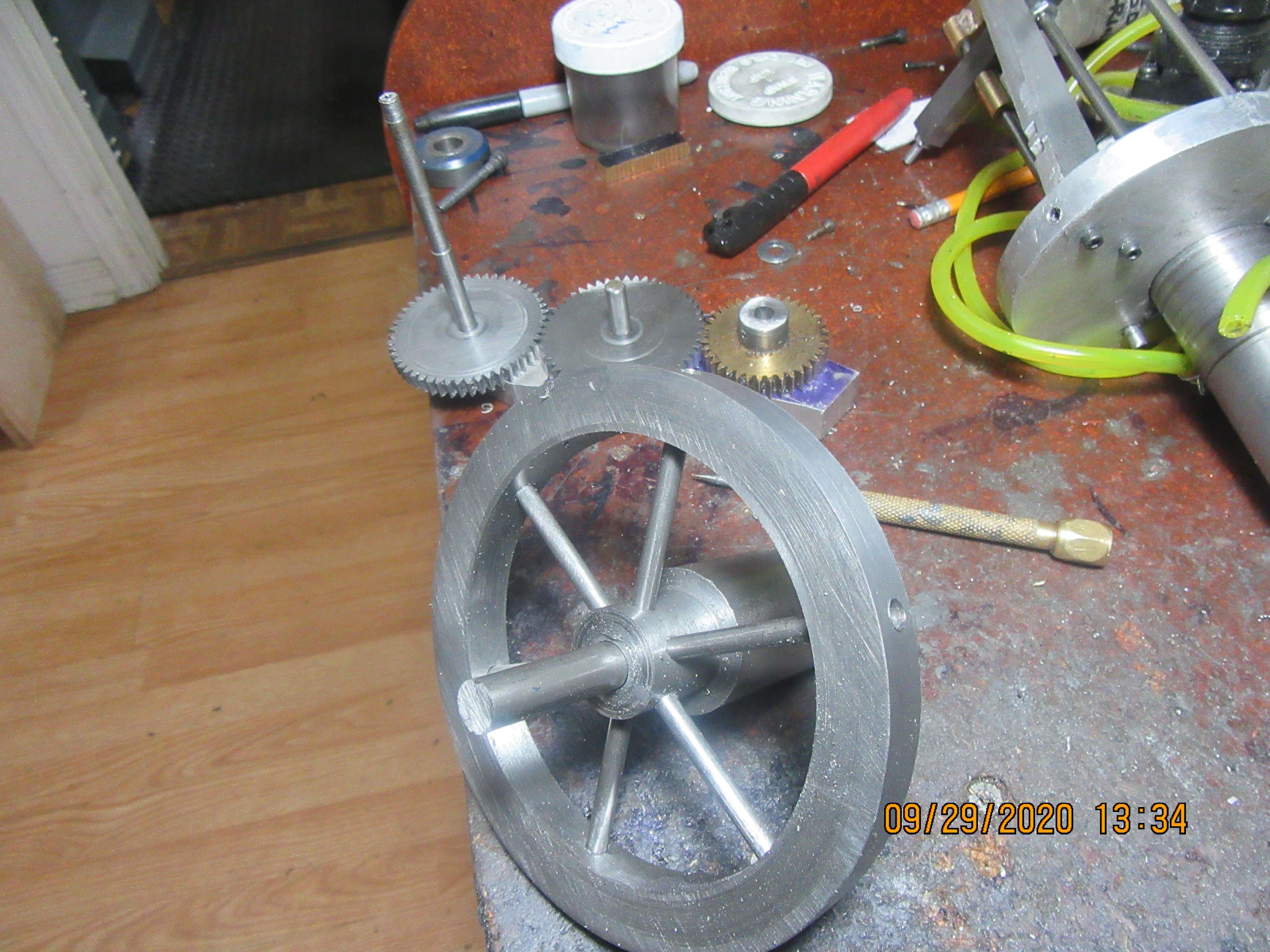
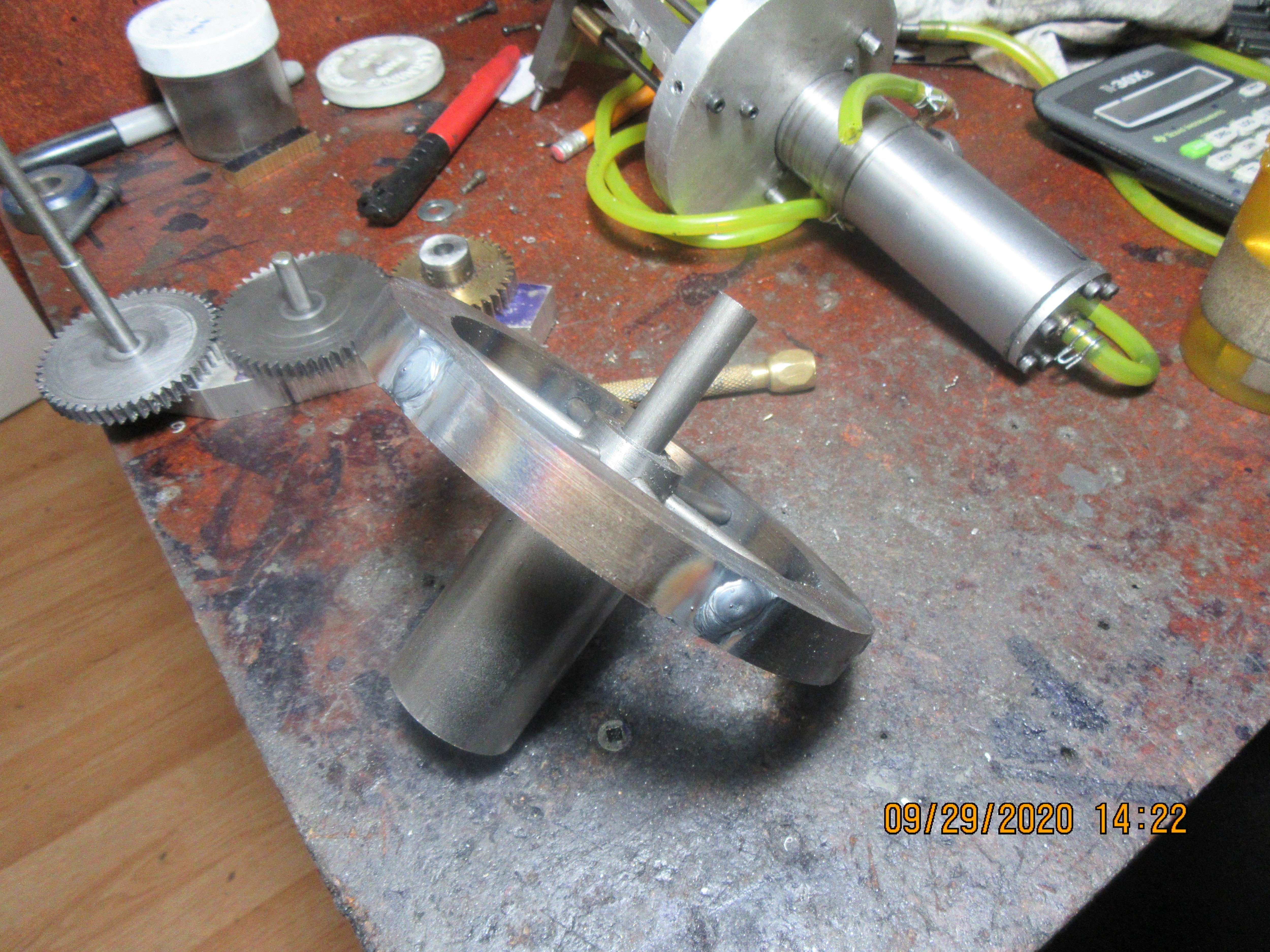
I've spent the morning preparing the 108 tooth gear blank. The gear as shown consists of outer rim, inner hub, and six spokes. If you can see it in the picture, the ends of the spokes are just below the root depth of the gear teeth. I'm going to use my new super duper TIG welder to weld the outer ends of the spokes to the outer rim, and fill the rest of the hole with filler rod up to the outer surface of the rim, which right now is 0.040" larger than the finished blank. Theory is that if the welding goes well, I will then machine off that extra 0.040" from the o.d. and machine the gear teeth. Then I will hold the gear by the i.d. of the rim, which is concentric with the outside of the outer rim, to finish drilling and reaming the center of the hub. In the background you can see that I have taken a piece of aluminum scrap and drilled it in three places for 1/4" diameter stub shafts to mount the finished 50 tooth and 36 tooth gears on to verify that they mesh correctly. (they do).

Everything went according to plan--Except, maybe the plan wasn't so good. The six 3/16" spokes have a lot of "give" to them. It becomes somewhat like trying to machine a sponge. Any pressure from the cutting tool and everything squirms all over the place. First I tried it without welding the spokes to the hub.--No good, in fact, terrible. Went back out to the main garage and welded the spokes to the hub on the side that doesn't show.--Marginally better, but kind of like trying to polish a turd. I will have a better idea tomorrow if I can save this or not, when I go to cut the gear teeth.

After thinking about the time and work involved in cutting 108 gear teeth, I've decided not to run with this idea. The gear is stuck right out on the front of the engine, and I hate wobbling and orbiting gears and flywheels worse than snakes. Not certain right now what I will use as an alternate method to spokes, but I will think on it and let you know.
Brian, When I make a flywheel like that, I screw the stems to the hub - the end of the stem having a screwdriver slot and the holes reamed to be a close fit on the spokes.
See below - soldered brass - but you get the idea.

This flywheel from my hypocycloid - I left the hub on its barstock - spotfaced and tapped it - then returned it to the 4-jaw - clocked it dead true.
Fitted the rim and spokes (locktite on threads) - persuaded the rim to run dead true with a mallet and then soldered it by flame heating the ring with a butane torch while still in the lathe (the amount of heat getting through to the chuck / lathe is nothing to worry about) - followed by a clean up turn of the outside diameter and sides.Only then parting off the hub from the barstock.
The result a flywheel that runs dead true.
Regards,
Ken
See below - soldered brass - but you get the idea.

This flywheel from my hypocycloid - I left the hub on its barstock - spotfaced and tapped it - then returned it to the 4-jaw - clocked it dead true.
Fitted the rim and spokes (locktite on threads) - persuaded the rim to run dead true with a mallet and then soldered it by flame heating the ring with a butane torch while still in the lathe (the amount of heat getting through to the chuck / lathe is nothing to worry about) - followed by a clean up turn of the outside diameter and sides.Only then parting off the hub from the barstock.
The result a flywheel that runs dead true.
Regards,
Ken
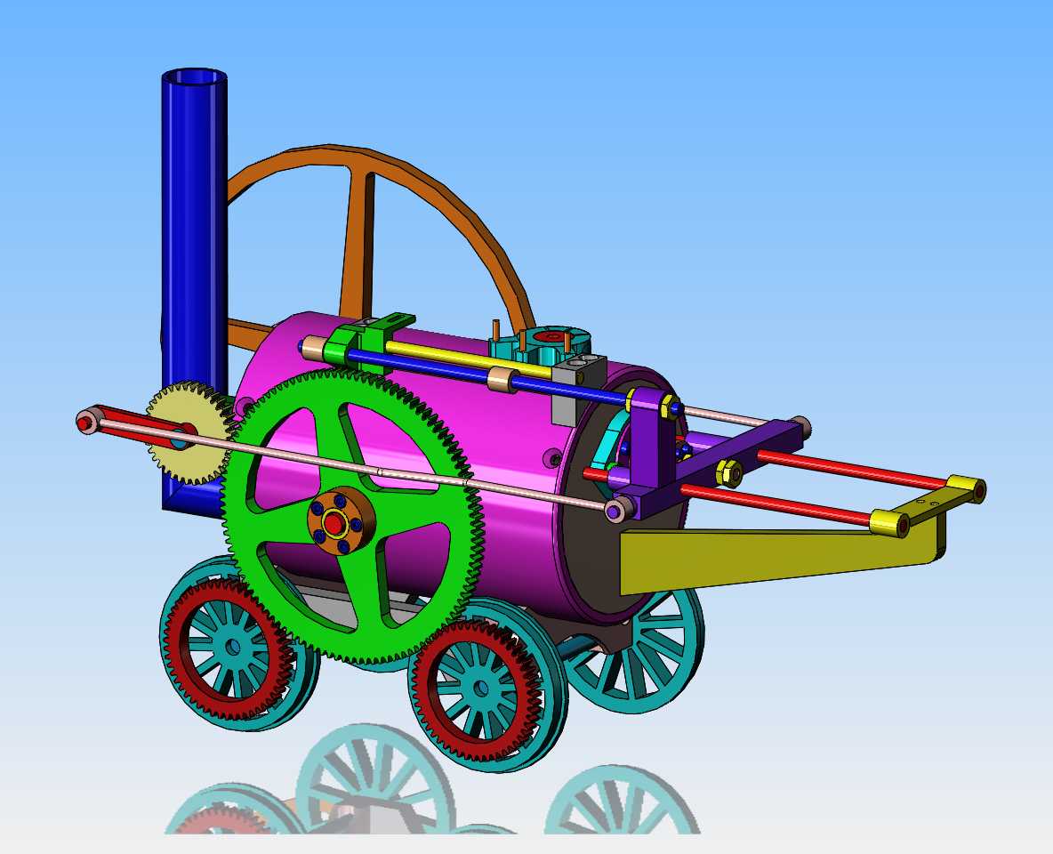
So, today we try for another kick at the can. My beautiful 108 tooth gear with spokes was not a good idea. Today we aim for something a little simpler, a gear machined from 1/4" mild steel plate with a bolt on hub and bronze bushing. At this point I have to say that I'm an incurable optimist.--I'm always sure that my parts are going to turn out beautiful, even when previous experience has shown me different. I have learned (over and over again) not to weld on things and expect them to stay true and square and symmetrical.

Holey crow!!! Start over again with 1/4" hotrolled plate.
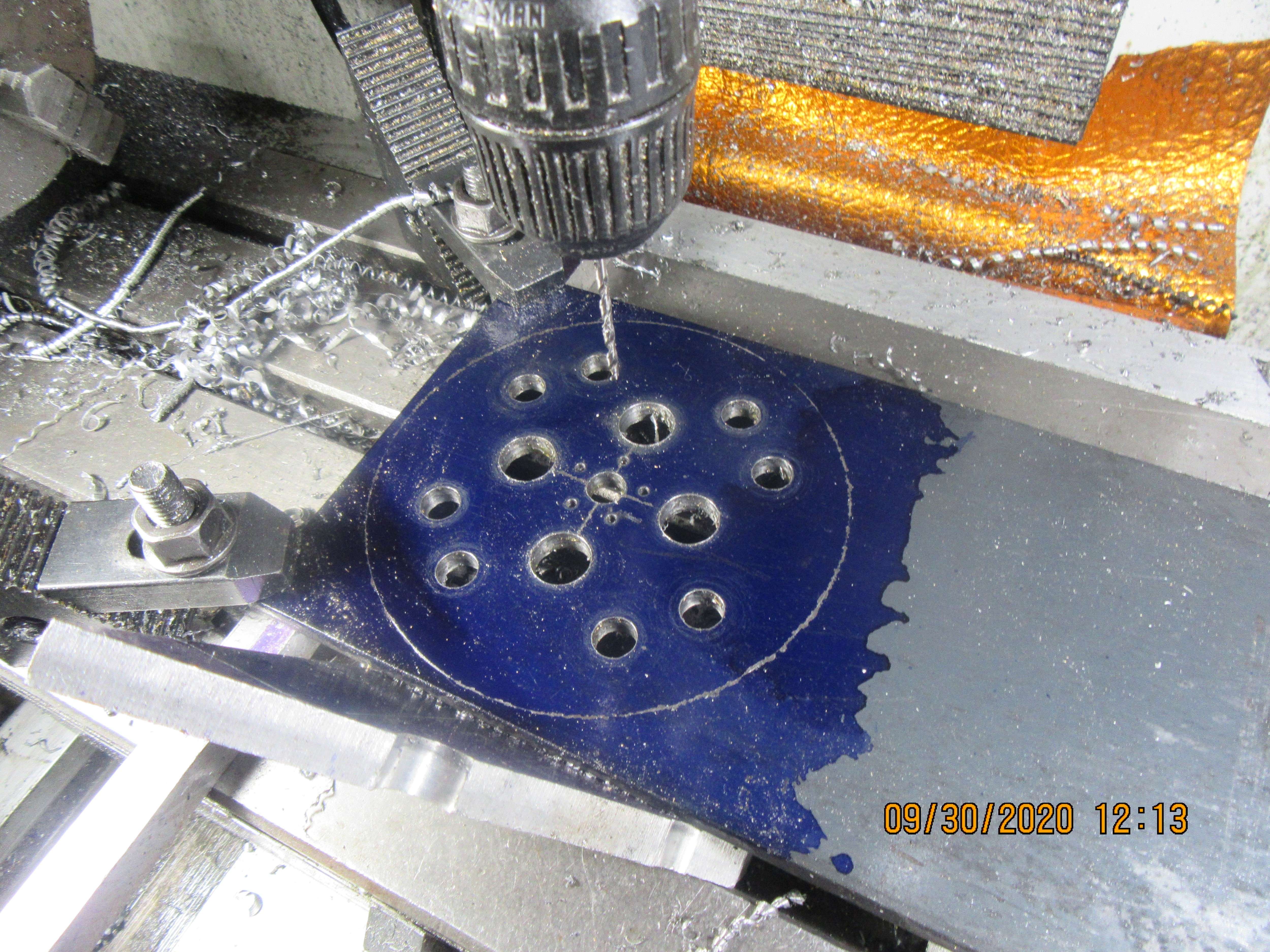

And more of the same, using the "EBVQ" method. (Eats blades very quickly).
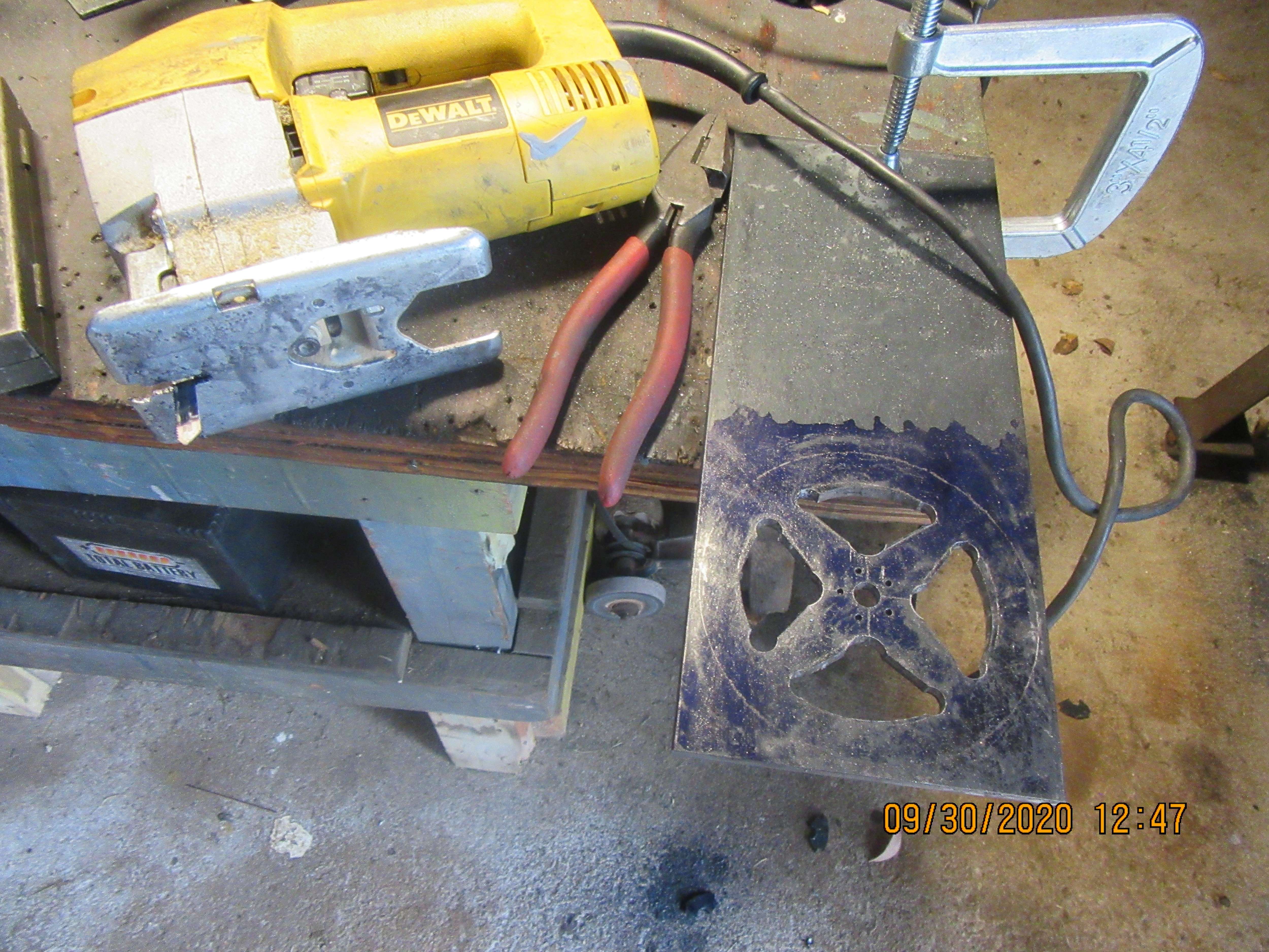

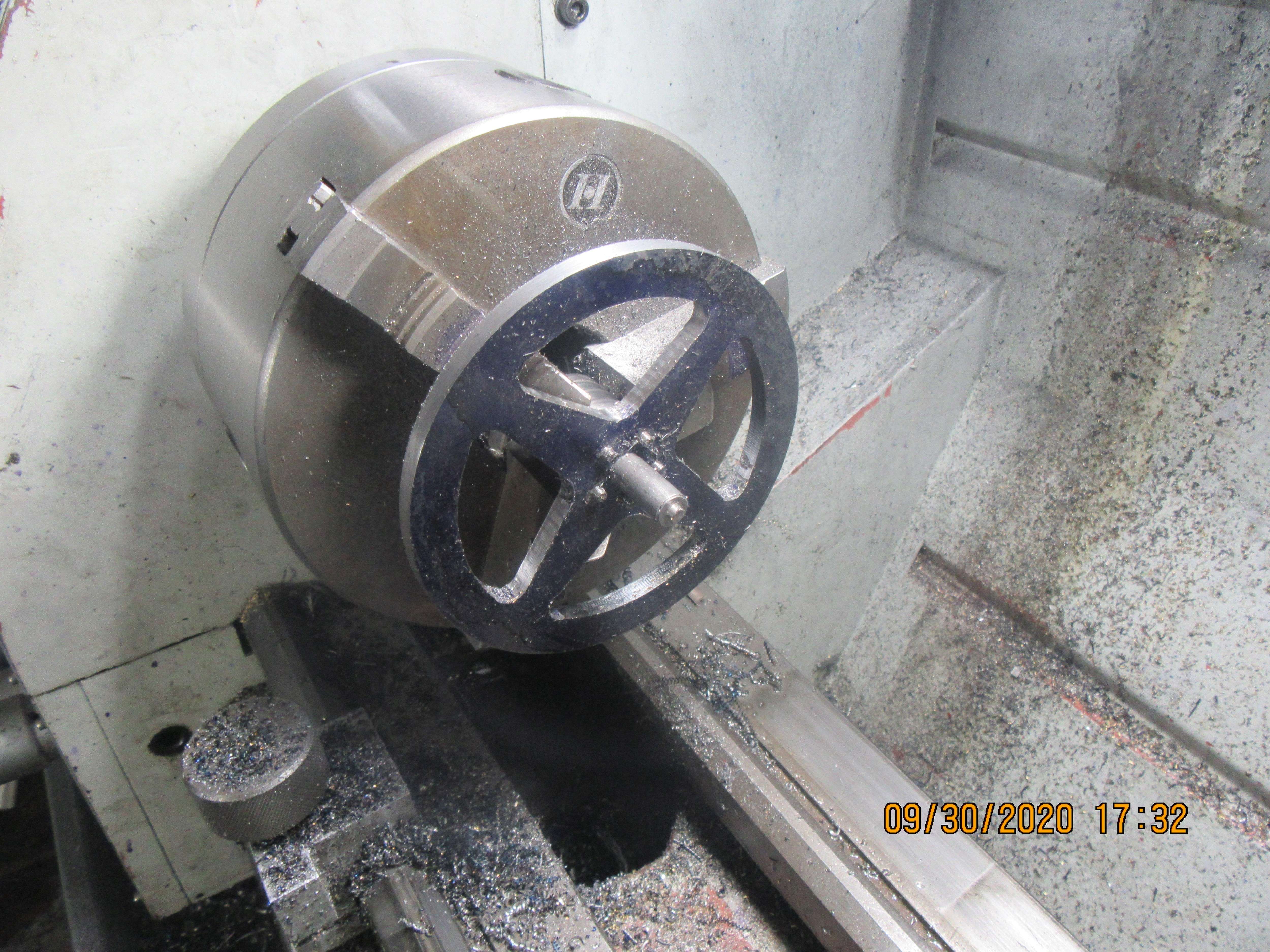
In this shot, the gear profile has been very roughly cut out on the bandsaw, and a hub is attached to it. This lets me grip the hub in my rotary table chuck, and machine the radiused area of the windows. The sides of the windows have not been machined yet, but that will be my next step.
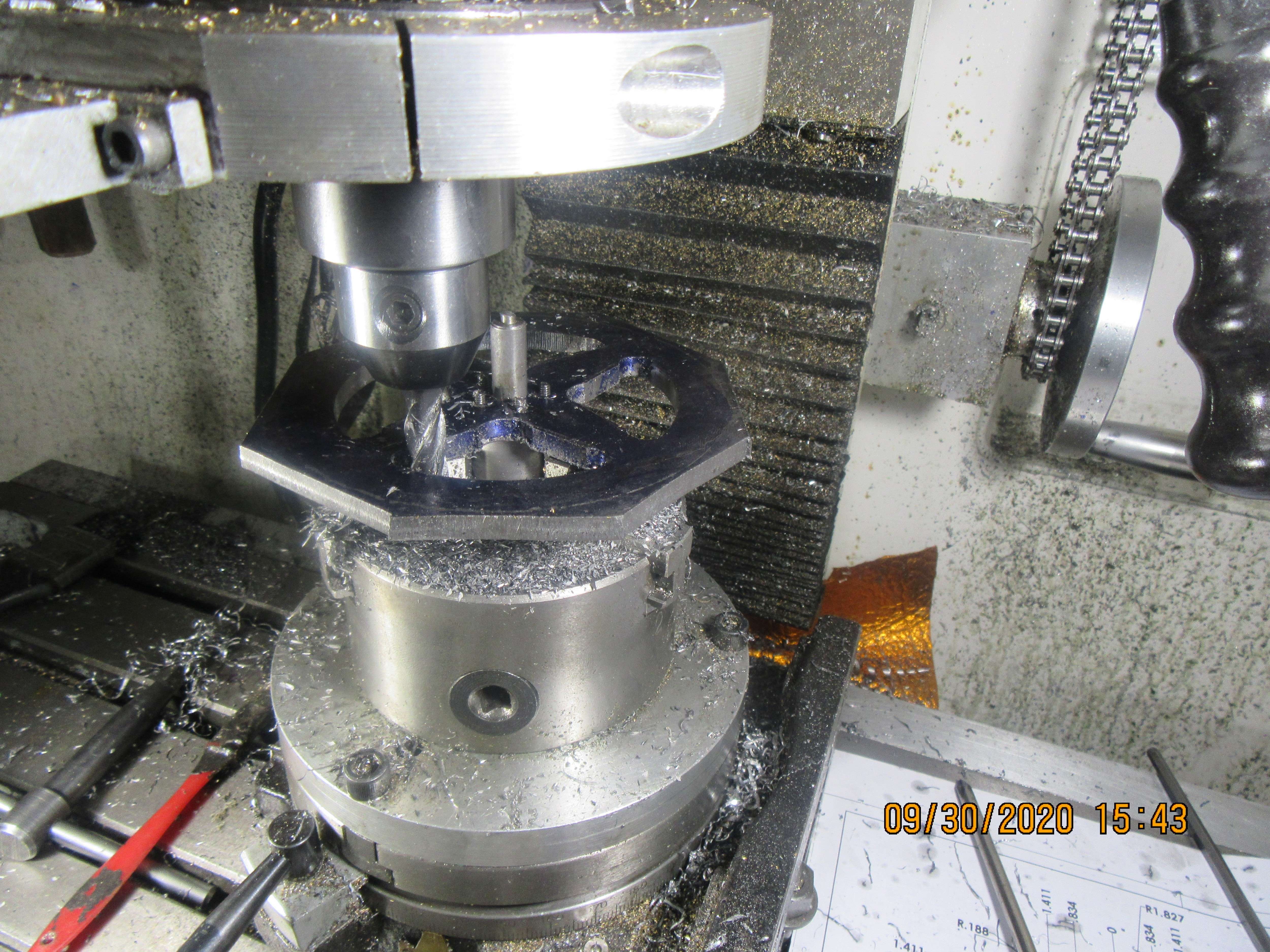

Machining the sides of the windows was easier than I thought it would be. Once you move things around with the X and Y table controls and the rotary table until you have one of the window sides parallel, (I took 0.080" depth of cut until I was thru the 1/4" plate), then if you have 4 windows you can just advance the rotary table 90 degrees and you are ready for the next side.
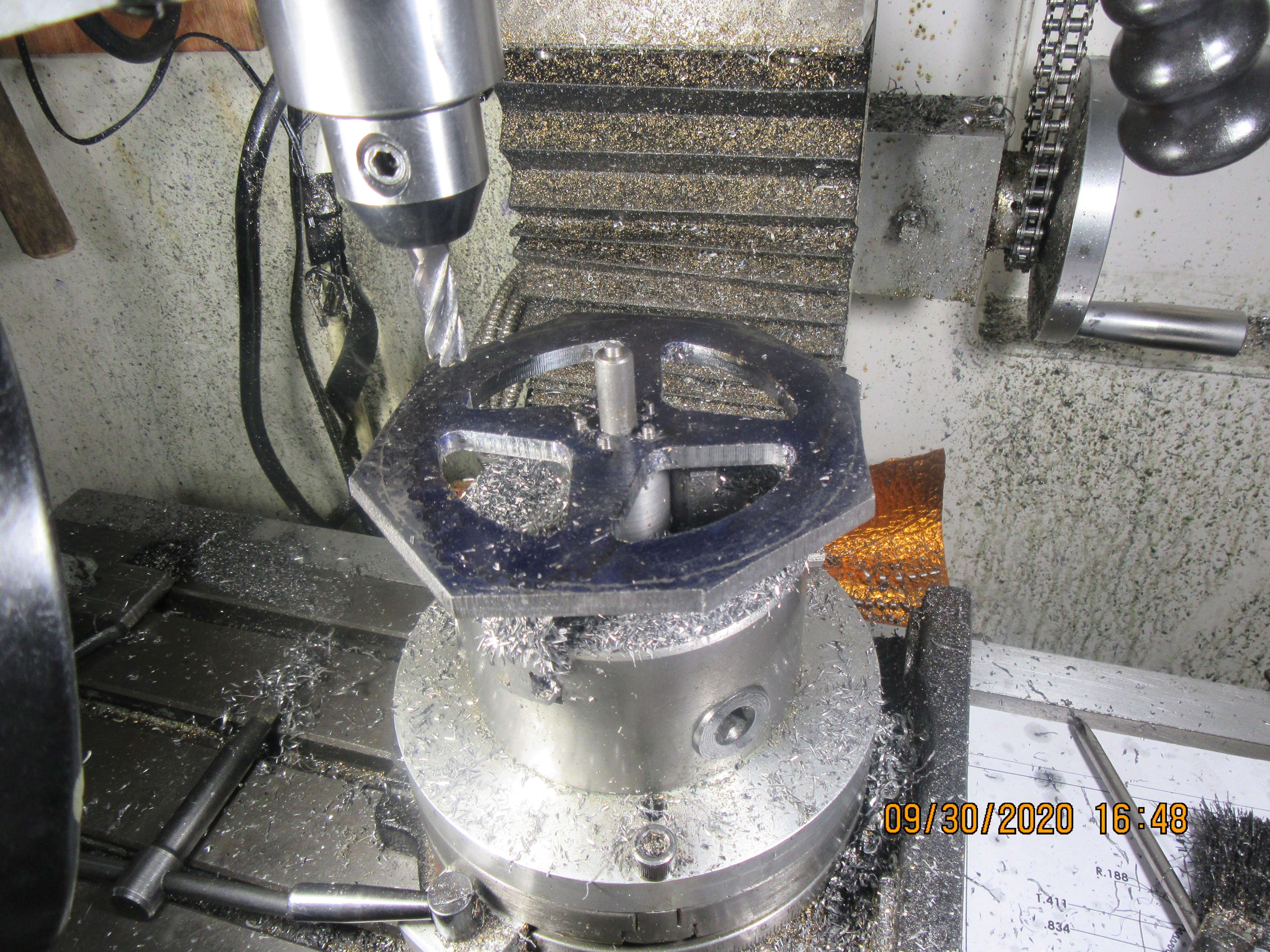

And finally, at the end of the day, the gear is ready to have it's teeth cut. This is about where I left off yesterday. It becomes pretty clear why people make large gears and flywheels with either solid webs or circular holes in the webs. It makes far greater economic sense to buy a flywheel casting or have a gear or flywheel water-jet cut. I still have "filing and fettling" to do on this gear but it is turning out like I had hoped.

Similar threads
- Replies
- 386
- Views
- 142K


