Julius sent me this today, an animation of how the four way rotary steam valve is operated on the original Trevithick engine.
You are using an out of date browser. It may not display this or other websites correctly.
You should upgrade or use an alternative browser.
You should upgrade or use an alternative browser.
Building the Trevithick engine
- Thread starter Brian Rupnow
- Start date

Help Support Home Model Engine Machinist Forum:
This site may earn a commission from merchant affiliate
links, including eBay, Amazon, and others.
I am going a bit batty this morning, checking to see that the correct ports are covered and uncovered in the cylinder as the piston and valve move back and forth in the cylinder. This is the kind of thing that you really want to get right on paper (or computer) because the next phase, building it in metal gets costly and time consuming if the ports aren't where they should be.
It's been a long and interesting day. I have taken the cylinder that Julius sent me, changed the diameter and the stroke length, eliminated some of the seals that crossed ports in the cylinder and changed the piston rod size. All I can do now is hope that I got it right and build it. I don't have a "safety net" of other designers and engineers to check some of this stuff for me. I won't build anything else on the project until this cylinder is finished, because this cylinder is the heart of the whole operation. There are no cams or eccentrics on this engine. The spool valve inside the end of the cylinder replaces all of that. There are seven ports on the sides of this cylinder. I am going to solder short lengths of small brass tubing to the outside of the cylinder at the ports and use flexible nylon tubing to connect them all. It will all be hidden inside the body of the Trevithick boiler. I will keep you posted as this develops.
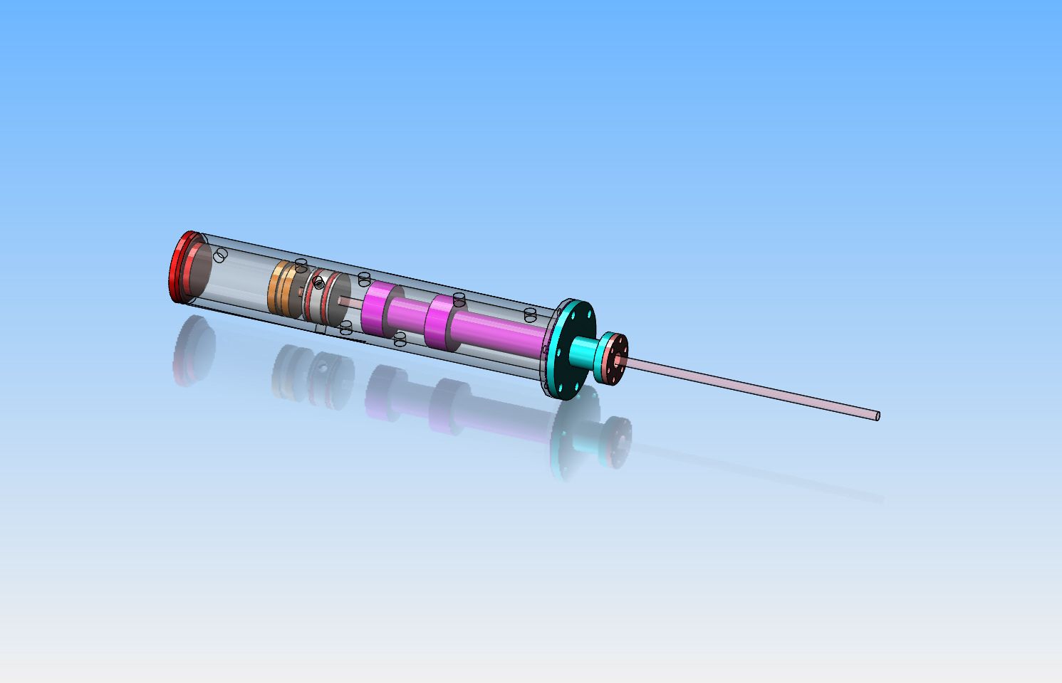

This morning the new cylinder is completely designed. I have moved all of the ports around into the bottom 60 degrees of the cylinder so they can be connected with flexible tubing. I have also redesigned the cylinder and end caps so that there is no welding or silver soldering, because I am concerned about warping the long cylinder from heat related issues. The cylinder body is now made from much heavier wall material so that I can tap the ports for 1/4"-20 threads, which lets me screw in the hose barbs with a bit of loctite so no heat is involved. I got some rather disturbing news this morning from Julius. He doesn't know if anyone has ever actually built this cylinder or not. To my knowledge I have never seen one like this myself. I don't care to be a guini pig for untried designs that haven't been built successfully by somebody else.
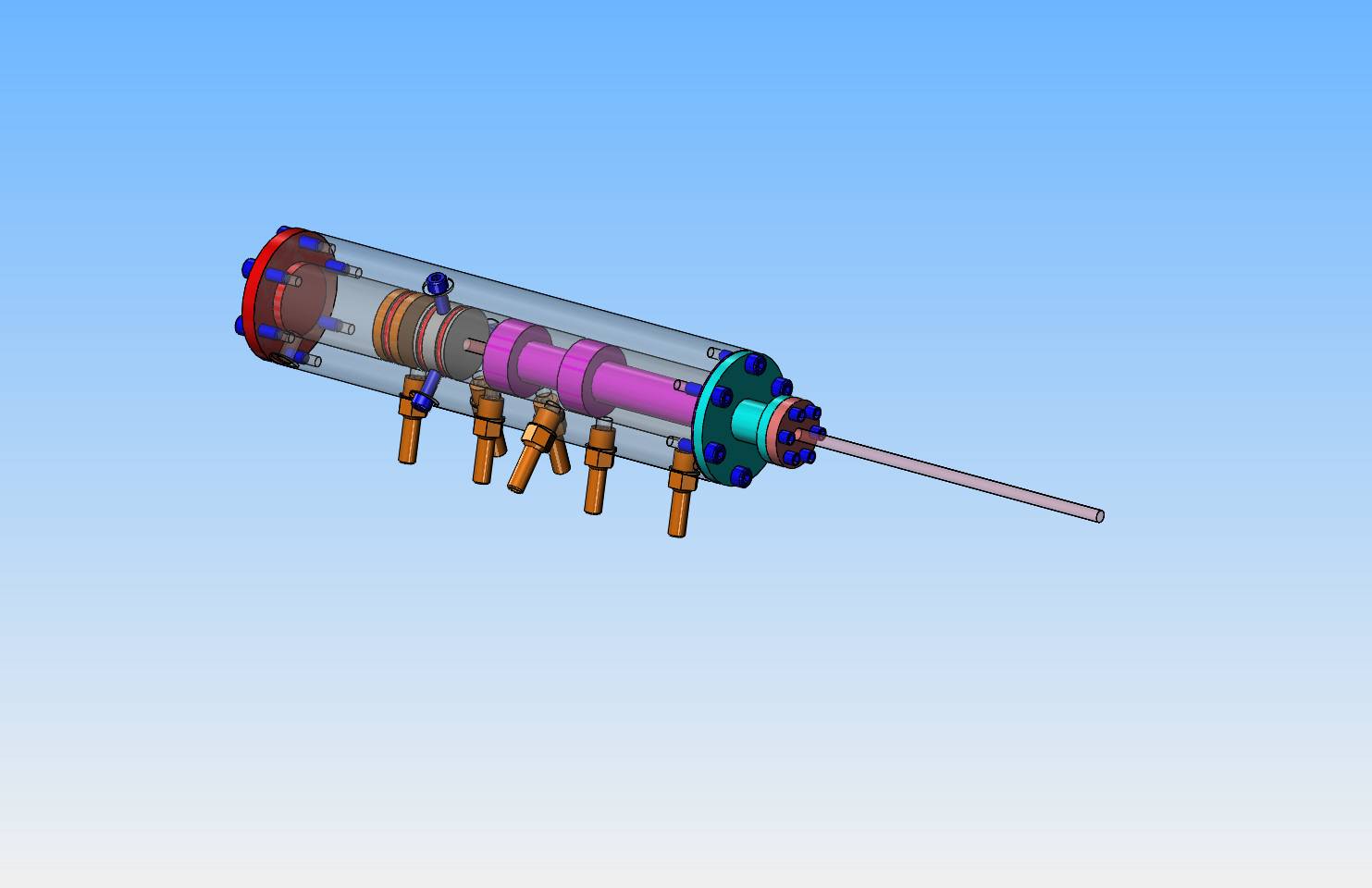

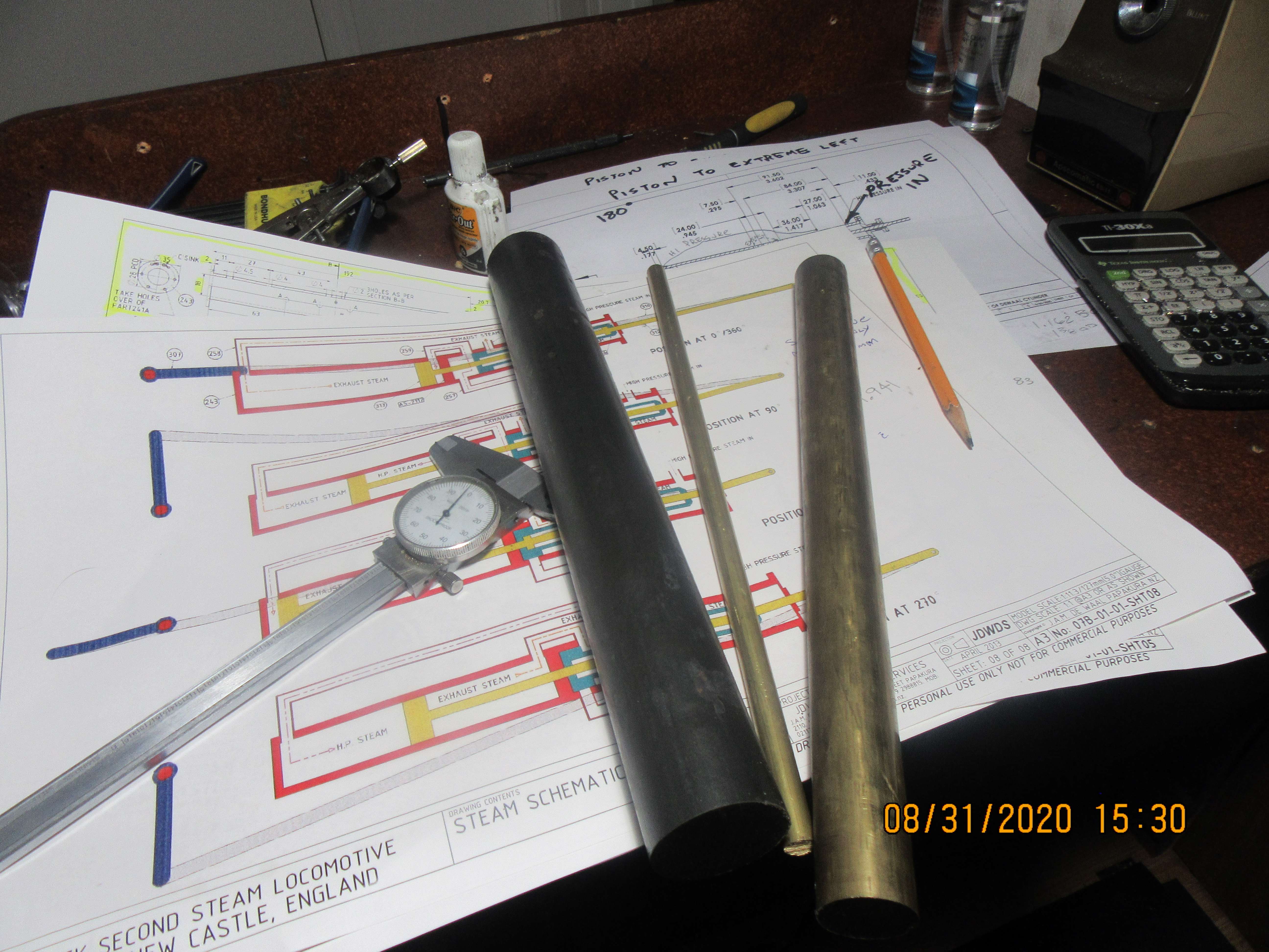
I have decided to go ahead and build the cylinder even though nobody knows if it has been built before to Julius' drawings. If it works, then Hooray, I'll be a hero. If it doesn't work, I will be able to salvage most of it to work with a more conventional valve system. I picked up the material for it today. The main cylinder body is going to be made from hot rolled steel. This is not something that I would normally use, but since the engine will be ran on compressed air it should be okay. I generally would use grey cast iron for a cylinder if it was for an i.c. engine or driven by steam.

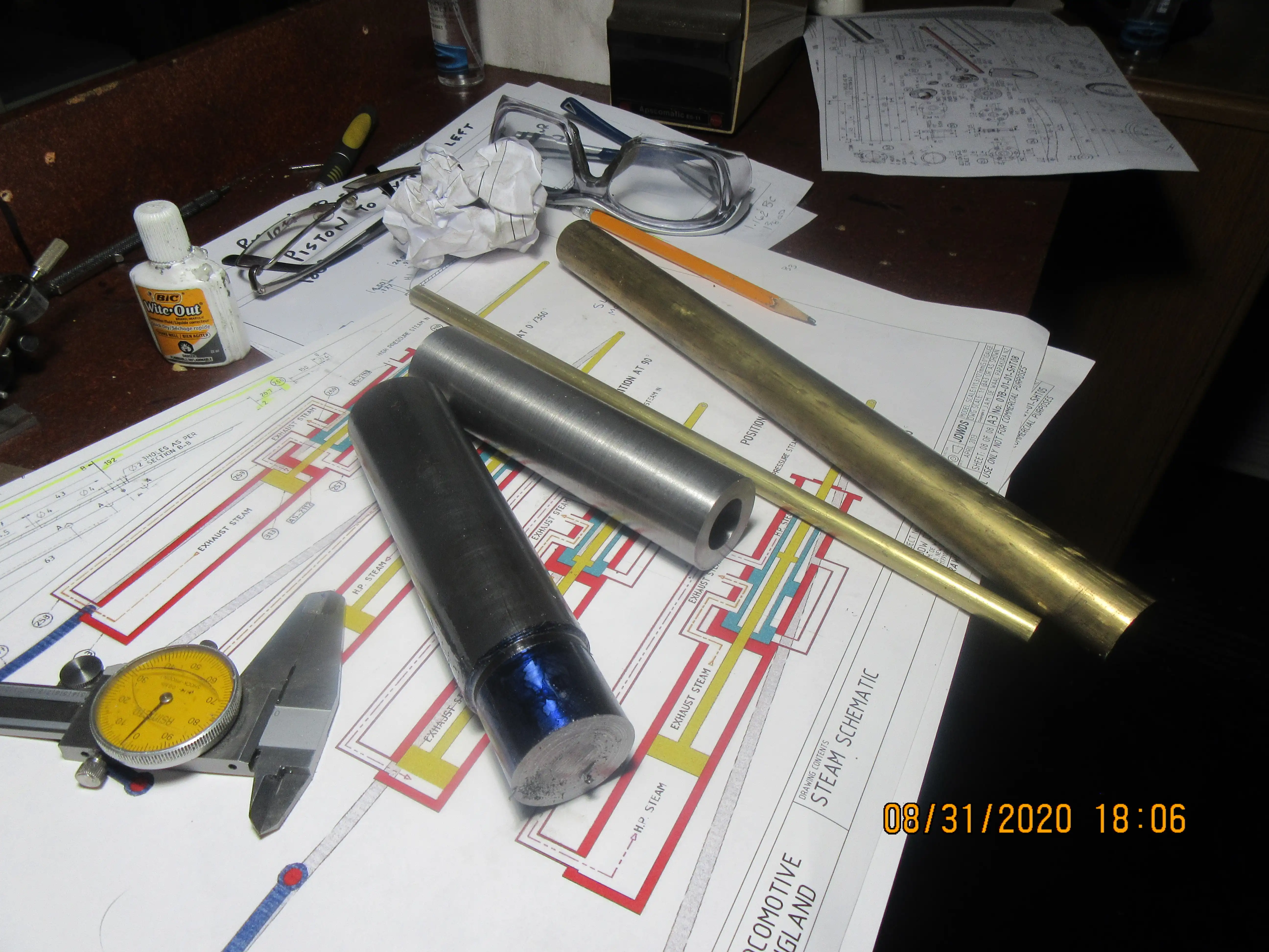
And the ugly 1 1/2" piece of hot rolled has yielded a nice cylinder. 1.375" o.d. x 0.75" i.d. x about 5 1/2" long. O.D. machined with brazed carbide at 680 rpm, inside drilled and reamed to 0.75". Hot rolled steel is such a nice steel to machine. I can get a much nicer surface finish on hot rolled than I can on cold rolled. Tomorrow I have about a billion holes to drill and tap.

![DreamPlan Home Design and Landscaping Software Free for Windows [PC Download]](https://m.media-amazon.com/images/I/51kvZH2dVLL._SL500_.jpg)
$0.00
DreamPlan Home Design and Landscaping Software Free for Windows [PC Download]
Amazon.com Services LLC

$34.74
$49.99
Becker CAD 12 3D - professional CAD software for 2D + 3D design and modelling - for 3 PCs - 100% compatible with AutoCAD
momox Shop

$599.00
$699.00
FoxAlien Masuter Pro CNC Router Machine, Upgraded 3-Axis Engraving All-Metal Milling Machine for Wood Acrylic MDF Nylon Carving Cutting
FoxAlien Official

$99.99
AHS Outdoor Wood Boiler Yearly Maintenance Kit with Water Treatment - ProTech 300 & Test Kit
Alternative Heating & Supplies

$39.99
$49.99
Sunnytech Low Temperature Stirling Engine Motor Steam Heat Education Model Toy Kit For mechanical skills (LT001)
stirlingtechonline
I spent some time designing this morning, and decided to make the piston rod 3/16" diameter with all the attendant changes to parts which mate with the piston rod. (It was 1/8" diameter before). I am happy with things as they are now, and the success of this design depends on the drawing of the cylinder I received from Julius. You have to admit---it looks pretty wild!!
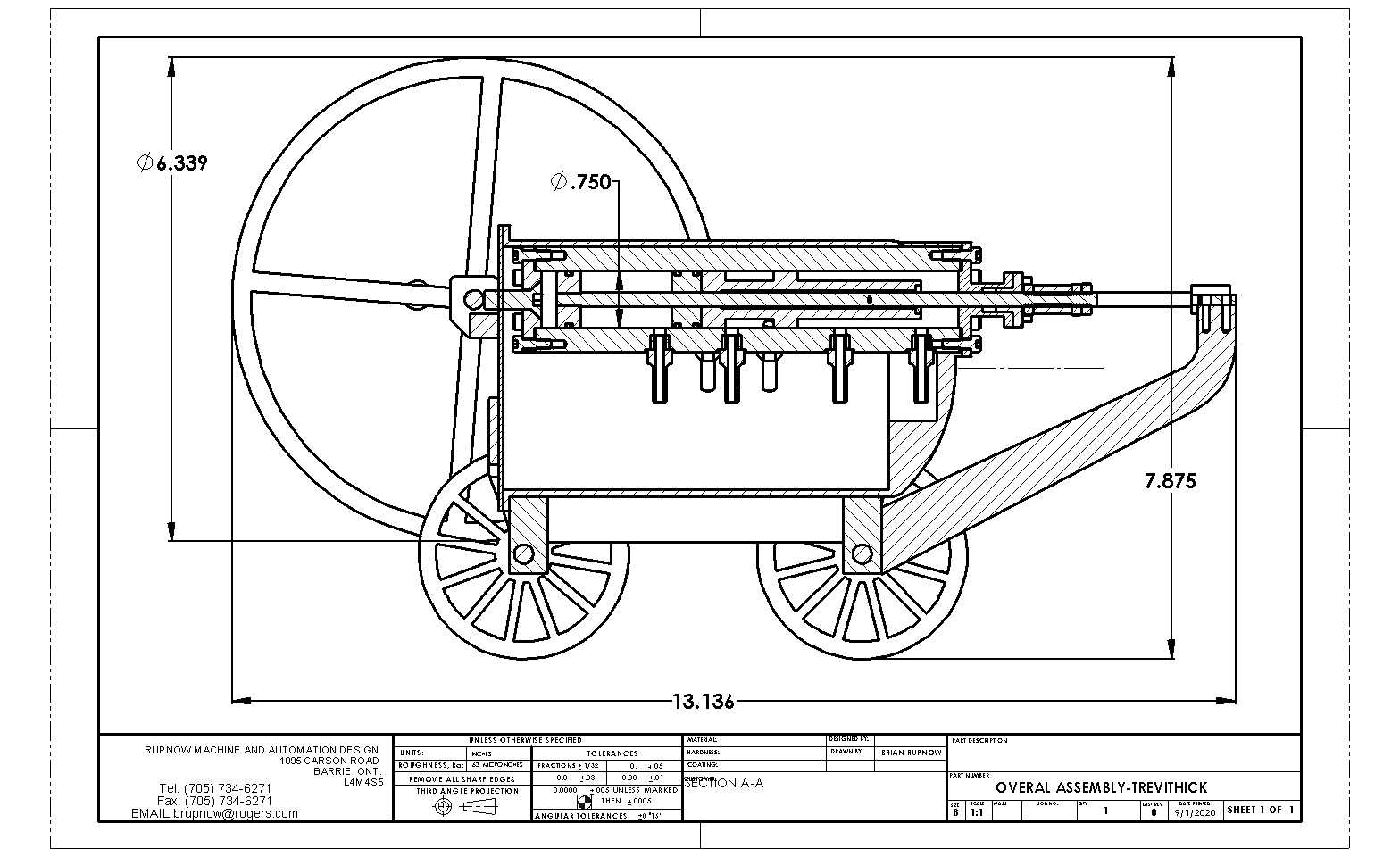

Looking great - but I cannot get my head around how that valve works - is it a spool valve ?
Regards, Ken
Regards, Ken
Ken, I really don't know. It is shaped like a spool valve, and it travels back and forth with the cylinder rod. This concept was designed by Julius DeWaal in New Zealand and he doesn't know if anyone has ever built it.
Yow!!!--That's a lot of holes. Hope they're all in the right place---
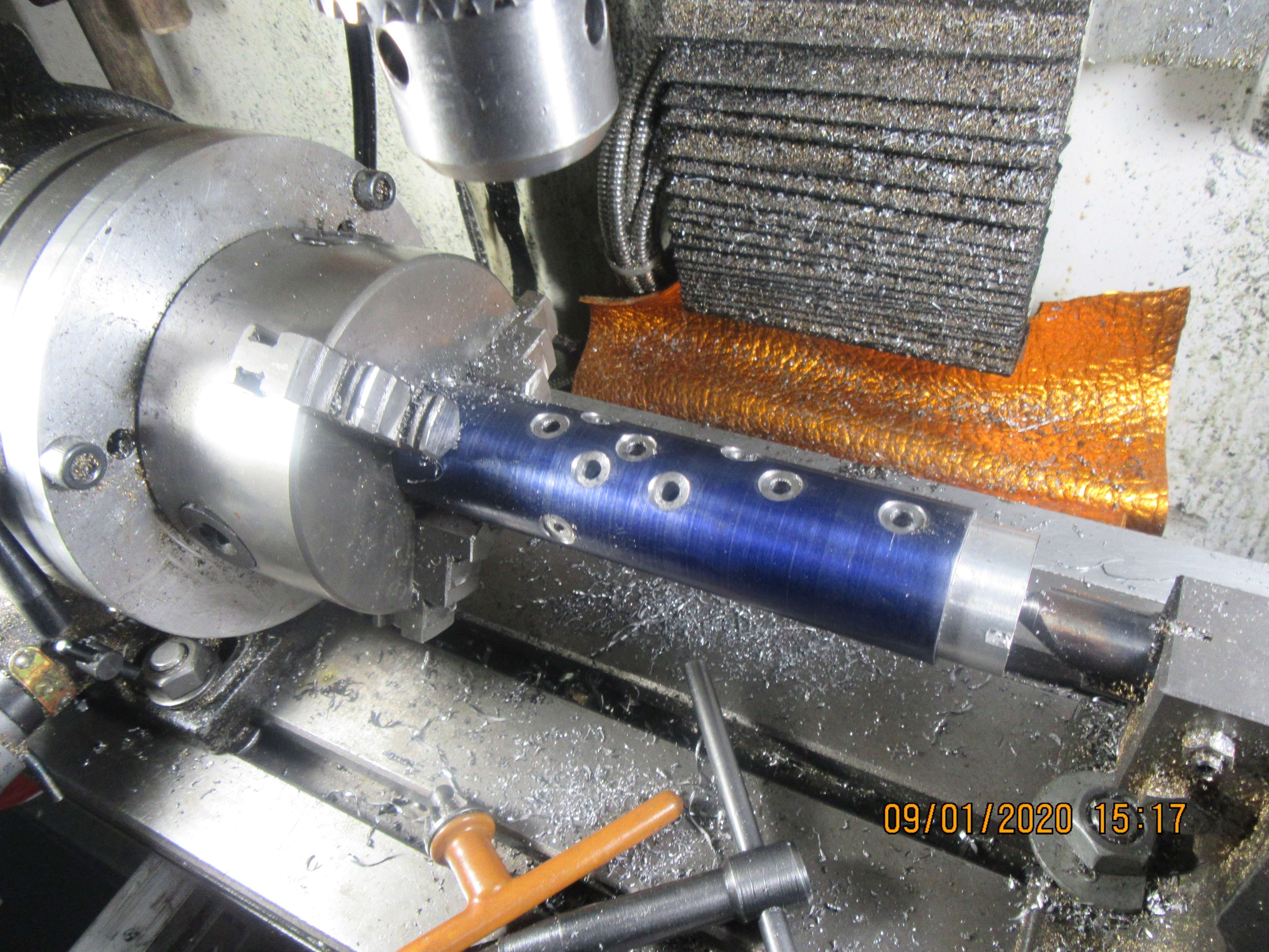

I'm slowly going ahead with the valve as designed by Julius. We have visiting grandchildren this week, and next week after they all go back to school it will be too dangerous for good wife and I to see them until a Covid vaccine is found. As for the valve which Julius designed, I can see the theory behind it, but I simply can't tell if it works until I have built one to see if it works or not. I think the cylinder is going to have a large "dead spot" at each end of the stroke, but with a large enough flywheel (which the Trevithick engine does) it may not matter. I have almost melted the internet searching for information about the original Trevithick 4-way valve, and the good news is that I think I have sussed it out. Now, whether the Julius design works or not, I simply have to build a rotary valve engine. If I do, I will publish the drawings on all my forums because this stuff is so neat that everyone should have free access to it.
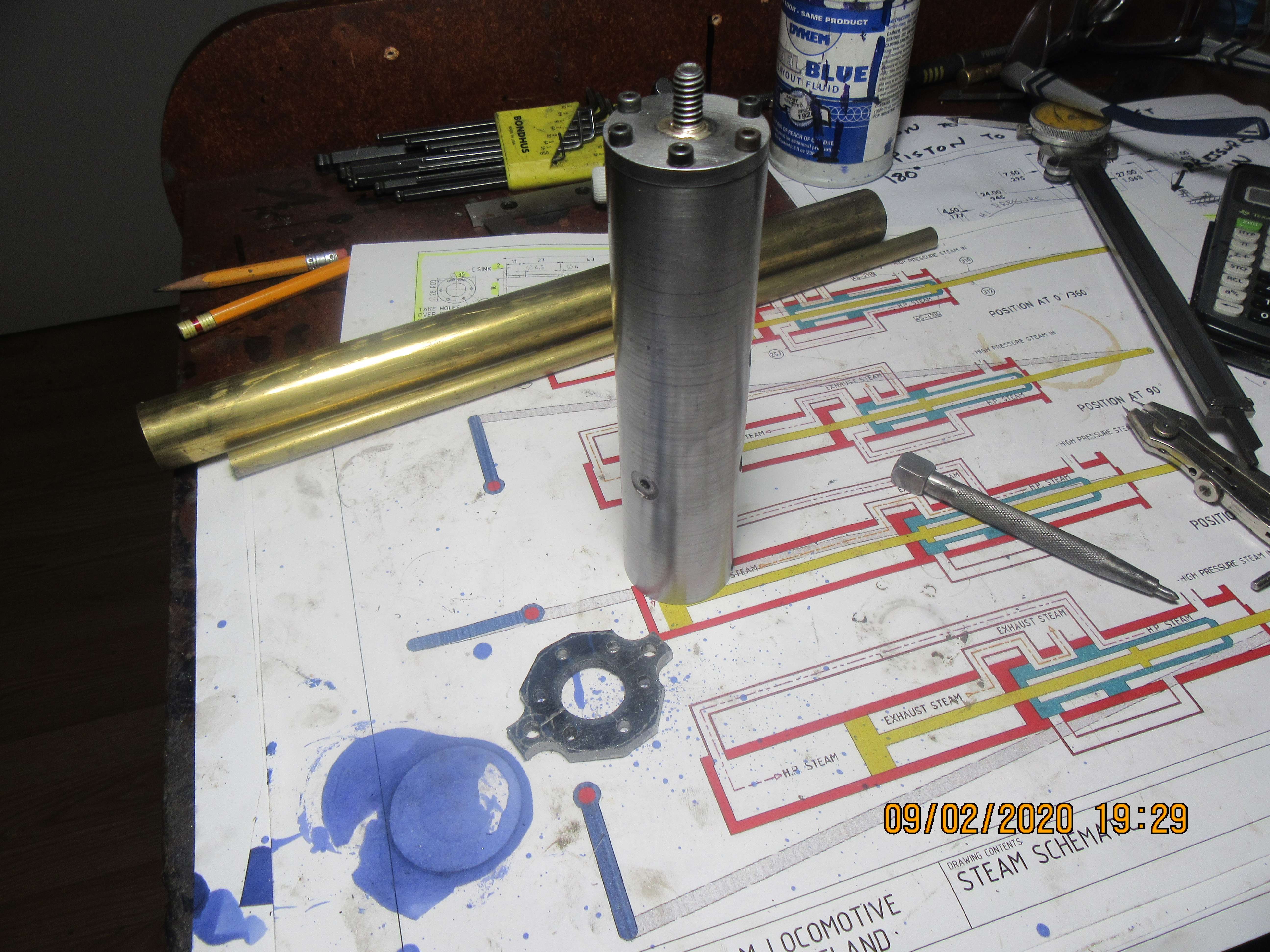

Brian, I don't know if this helps - but this is the 4 way valve I designed for my elbow engine - it acts as a throttle and reversing gear - swinging it through 90° takes you from full ahead to full astern. Mid position is stop.

It relies on fit to avoid leakage - but it has worked well so far.
I had considered using a non-self holding taper which could be lapped into a near leak proof fit and could be tightened as necessary to accommodate wear (as opposed to the cylindrical spool indicated).
It simply swops the cylinder connections from one end to the other so it could also be used to cycle a cylinder.
My 2c worth.
Regards, Ken
Last edited:
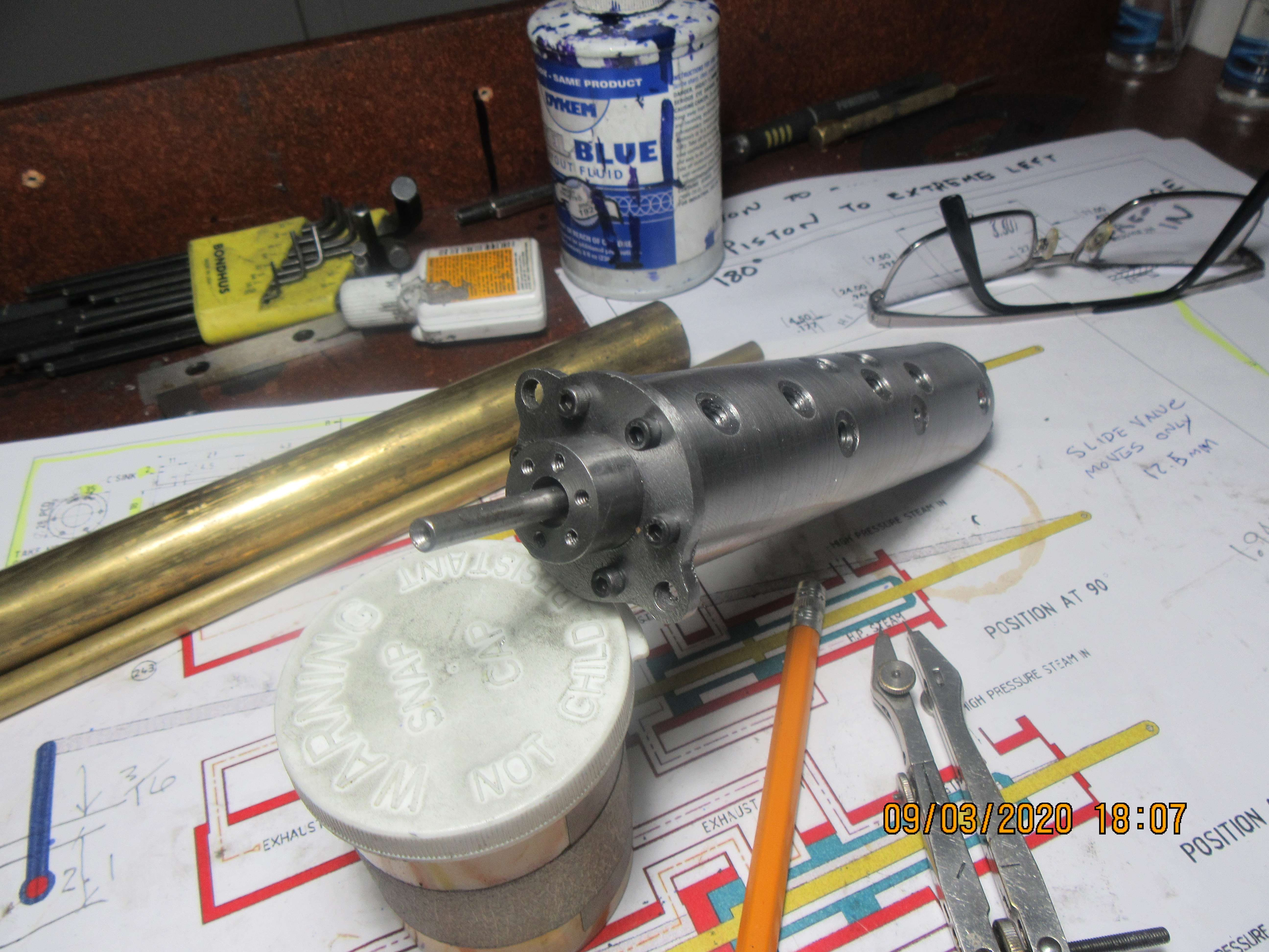
Today we have both cylinder end caps finished. That little bit of shaft you see sticking out the end isn't really the piston rod.---I'ts just a "fooler". I still have to make the packing gland, and then I will start on the hose barbs that screw into the sides of the cylinder. I miscounted earlier when I said there were seven ports.---Actually there are eight.

Ken1--Thank you for the drawing. When I get this current cylinder configuration finished I'm going to build a cylinder with this valve on it.---Brian
Eight little hose barbs, all in a row. This cylinder is going to look like a porcupine. If I can just get a 1/4"-20 thread on the end of each one without destroying it, I'll be very happy!!!
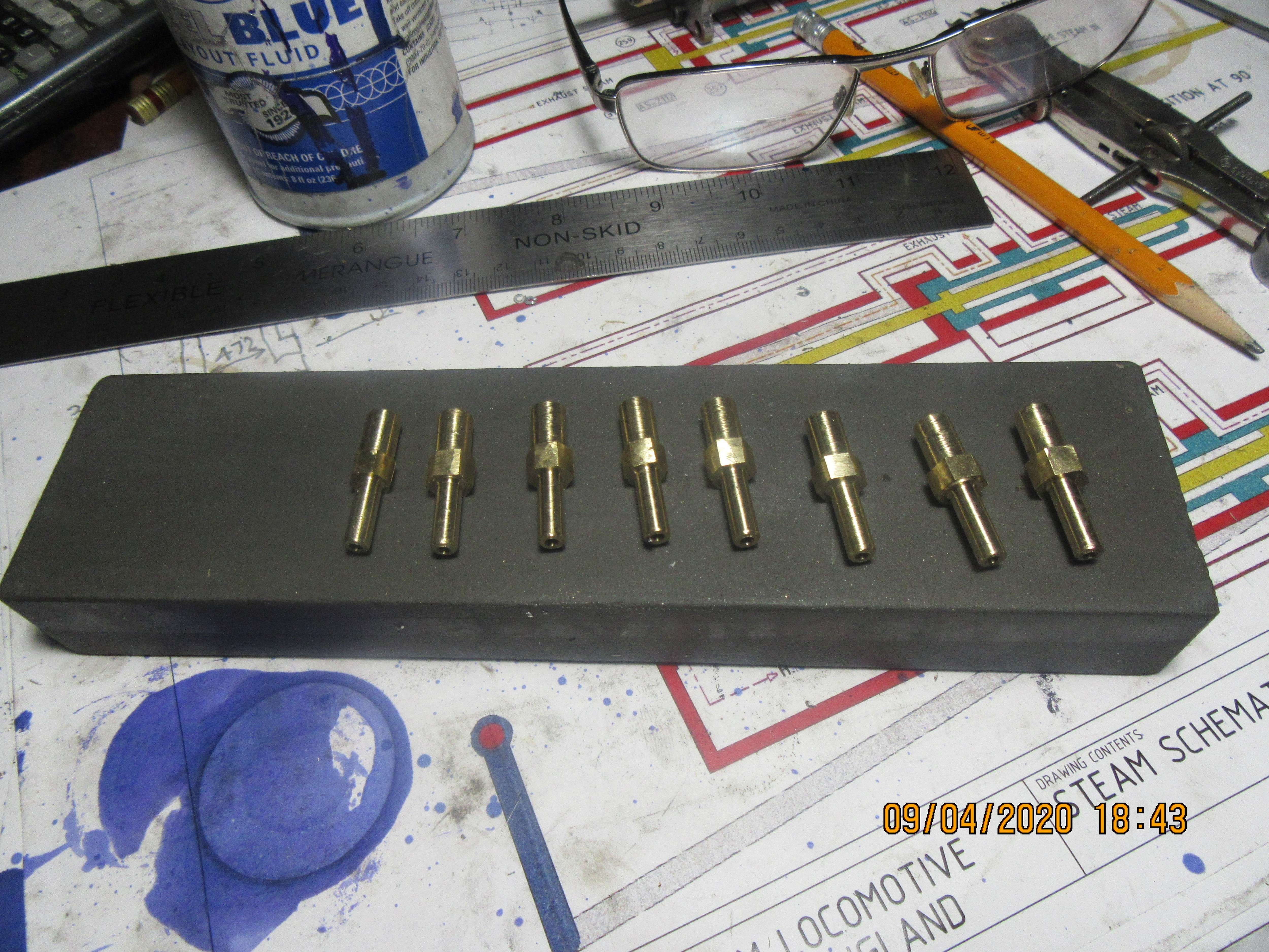

Brian, You ever thought of using 1/4x40ME like the steam guys use.Eight little hose barbs, all in a row. This cylinder is going to look like a porcupine. If I can just get a 1/4"-20 thread on the end of each one without destroying it, I'll be very happy!!!

- Joined
- Oct 1, 2010
- Messages
- 1,404
- Reaction score
- 431
I have used 1/4-28. That size is included in both my tap sets.
--ShopShoe
--ShopShoe
Perhaps not in the spirit of do it yourself - but Festo make barbed fittings for 2,3 & 4mm bore tubing in M3 & M5

I use bits like this on my models - the tiny self closing quick couplers are great.
That brass fitting in the middle I made myself.
Regards,
Ken

I use bits like this on my models - the tiny self closing quick couplers are great.
That brass fitting in the middle I made myself.
Regards,
Ken
Last edited:
Today yielded a piston, a spool valve, and a cylinder partition plate. Those o-rings are Viton---Didn't need to be because there is no heat involved, but that's what I had. I still have to drill and tap 3 holes in the cylinder partition plate.
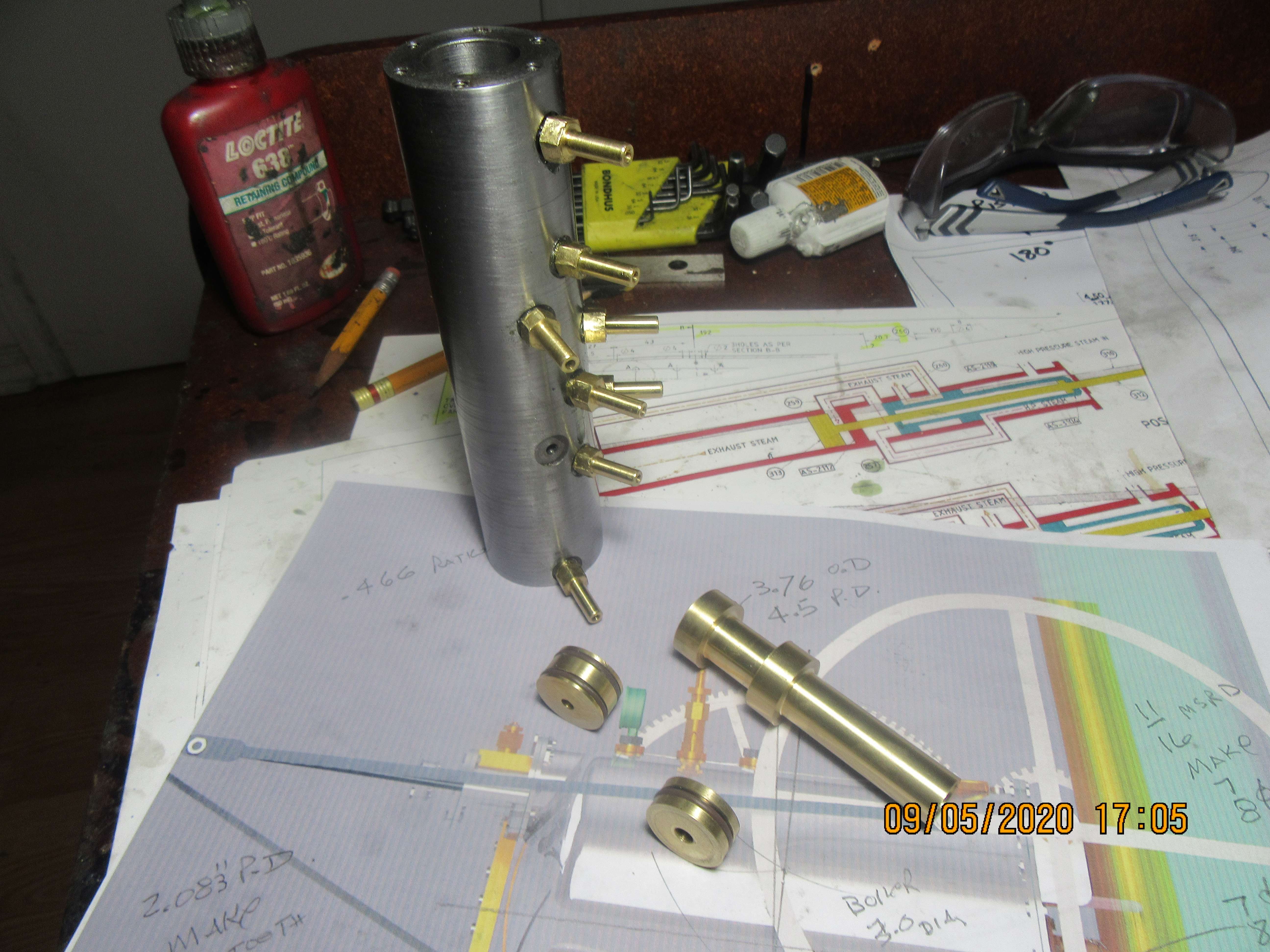

1/4"-20 threads suit all of my needs. The only place I use 40 threads per inch stuff is when I build the main needle jet for carburetors.
Similar threads
- Replies
- 386
- Views
- 142K


