Building the Pumpjack

Home Model Engine Machinist Forum

Help Support Home Model Engine Machinist Forum:

This site may earn a commission from merchant affiliate links, including eBay, Amazon, and others.
Of all the small steam engines I have built over the last 2 or 3 years, my version of Elmer Verburgs #33 mill engine seems to be the closest "fit" scalewise to drive the pumpjack. I will have to first finish the pumpjack and do some tests to see how much power will be required to run it, but I think this will be the one.
PUMPJACKWITHELMERS33.jpg
.
 
Good choice Brian - looks about right to my eye.
 
Thanks Tel---The pumpjack is on hold for the moment---After 4 weeks of no "real" work, the heavens have opened up and I have more "real" work than I can possibly do. Never rains but what it pours!!! :D :D
 
Ah well mate, you gotta grab it when you can - I'm a bit in the same sort of boat at the moment, with a few fabrication jobs on stream.

Meanwhile my Traxxas gear and pinion arrived yesterday and I found a good sized idle gear in my collection, so I might make a start on that bit (so they don't get lost) as soon as time permits.
 
Quick question tho' - your drawings just show the pump rod hanging through the base - My idea was to fit a collar and a light spring down under there out of sight so that there is some preload to keep the cables taut. Have you considered doing this?
 
tel said:
Quick question tho' - your drawings just show the pump rod hanging through the base - My idea was to fit a collar and a light spring down under there out of sight so that there is some preload to keep the cables taut. Have you considered doing this?

Oh, you sly devil, you!!! Thats exactly what I'm going to do!!! Thats why there's a thread in the bottom of the pump rod----
SUCKERROD.jpg
 
My customer called at 10:00 this morning and put a hold on the job while he "Sorts out some issues."---This kind of thing drives me crazy----But it did give me time to machine a couple of connecting rods and the stub shafts that attach them to the counterweights. ;D ;D
connectingrodsfinished003.jpg
 
Its probably going to end up looking like this. This will let me put a spring on the underside of the pump-rod to keep some tension on the wire ropes at the horsehead while it is operating.
OVERALLPUMPJACKWITHSTEAMENGINEANDNE.jpg
 
If you want to do it up right, make the box it sits on from transparent plastic. Fill it partially with mineral oil, and use the sucker rod to operate a small pump to actually pump oil.
 
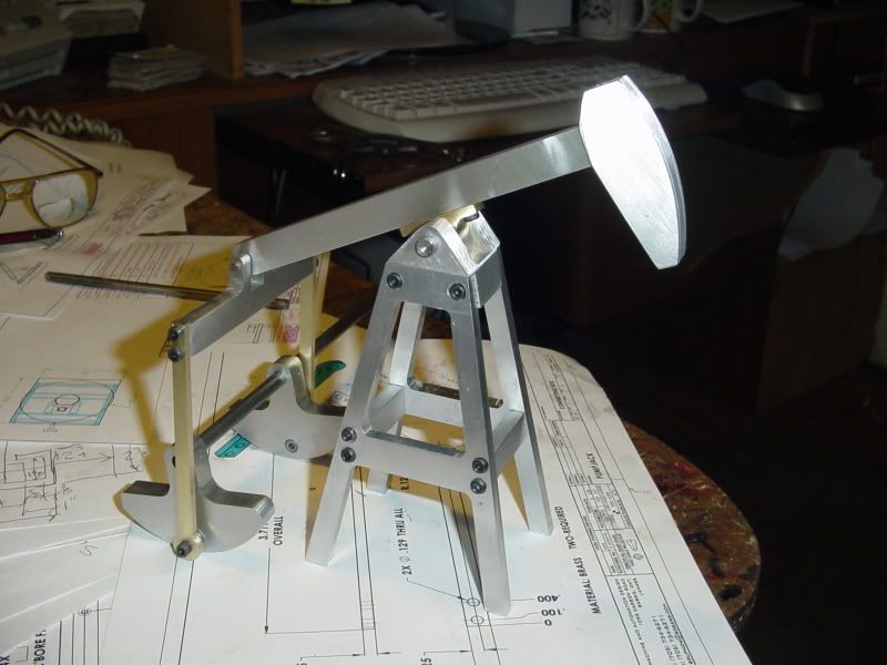
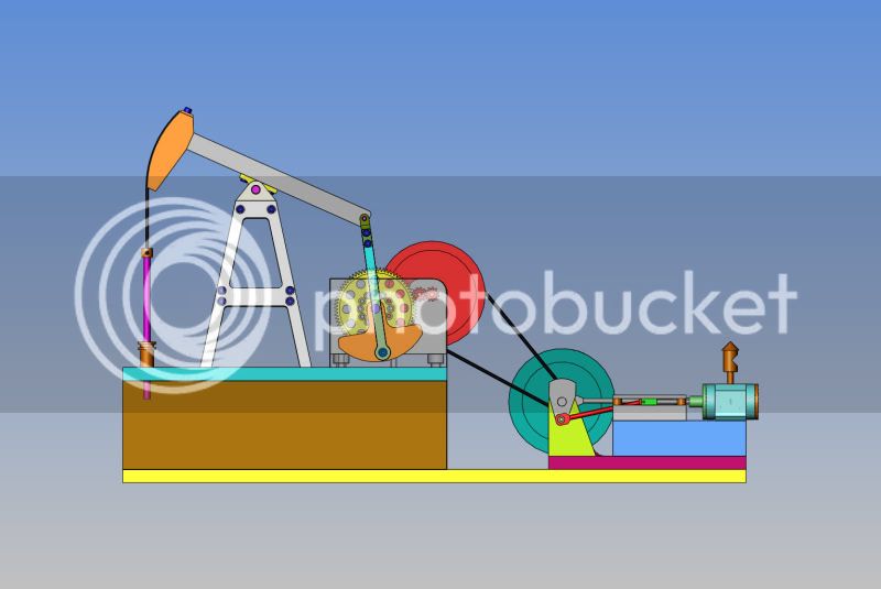
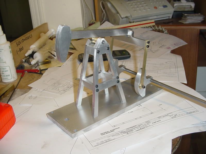
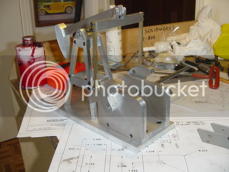
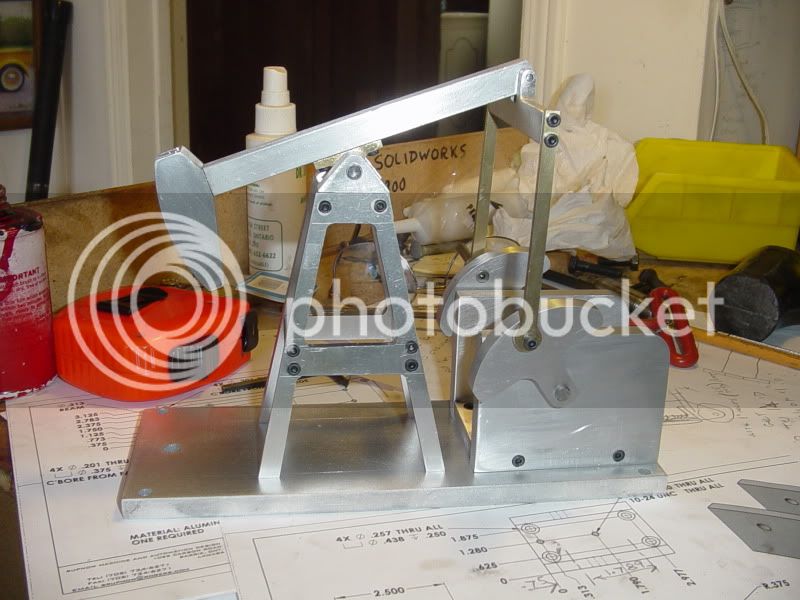
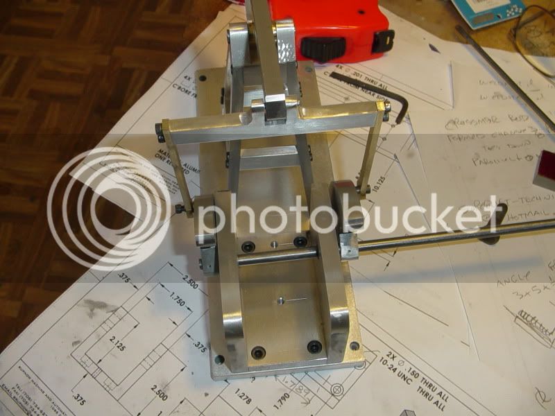
Marv---I have thought about that. This model is one of those which can "evolve" as it develops. I had thought more along the lines of leaving the sides in aluminum, but putting a small reservoir in the base and two pipes coming up through the top plate, near the pump rod. The one pipe would have a 180 degree hook in the top of it, and come up about half the height of the derrick. The second would have a funnel shaped top, and set perhaps 1 1/2" below the first pipe. With each stroke of the pumprod, there would be a visible "gush" of oil coming out of the pipe with the hook and dissapearing back down the funnel shaped pipe to replenish the reservoir. Of course, my main mandate for now will be to finish it more or less as shown in the model. If I like it, then I may add the pump.----Brian
 
Yes, all kinds of fun things are possible.

I would make the tank transparent with an inch or so of dark-colored oil on the bottom and a block of styrofoam floated on top of the oil to simulate a layer of shale overlying the oil "pool".

Have your outlet discharge oil into an open tank fitted with a standpipe overflow drain that keeps the bottom third or so of the tank filled with oil to make the pumping action more visible and realistic to the observer.
 
Todays offering is a base. Nothing too high tech, nor complicated here. As you can see, I lay all my holes out BEFORE I start to use the mill. I still use my edge finder and indicate all the hole positions with the table dials, but I like to know that when I go to drill a hole, its really going to be where I expect it to be. One of these days I have to buy a counterbore tool for a #5-40 shcs. I have been getting along very well using a 1/4" end mill to c'bore the holes, but I want to get the correct tool.---And while I'm buying that, I will buy a second set of hold downs for my mill table. Two are not enough----
MACHINEBASE002.jpg
 
I really like the way this is turning out.---Thought I might have trouble matching the holes in the baseplate to the tapped hole pattern in the 4 legs of the derrick, but I was a bit sly there---I built the derrick (tower) first, then made my hole pattern in the base plate to suit the tower.---And amazingly, it was very, very close to what I had originally designed!!!
MACHINEBASE004.jpg
 
Good Work Brian. I always get Nervous when drilling hole patterns and sometimes use a dial indicator if I have to move the dials in two directions. But that limits me to 2 inches of travel.

Great work. Thm:

Kel
 
I always get Nervous when drilling hole patterns and sometimes use a dial indicator if I have to move the dials in two directions. But that limits me to 2 inches of travel.

I solved that problem by making the stop that the (permanently mounted) DI bears against a long, movable rod. When I reach the limit of the DI, I just slide the rod so the DI reads zero again, then continue my measured movement.

Admittedly, a DRO would be a lot more convenient but I'm not going to put a $500 DRO on a mill that's worth less than that. Besides, making small models, I seldom have to make a movement that exceeds two inches.
 
Good Lord!!! I must have been smoking rope when I designed that gear reducer housing!!! 2.5" square stock----Who am I kidding??? I am going to start on that tomorrow---MADE FROM 3 PIECES OF 3/8" PLATE bolted and pinned together. Jeez, I hate it when I do stuff like that-----
 
;D Now why did I suspect that that might be the case - tho' you did mention the alternative at the time.
 
I got up this morning and resolved to build a reducer housing. This is the only picture I took as an "in process shot"--Nothing too exciting here--Layout holes, set up in milling vice, and go nuts with various drills, taps, and counterbores---
reducerhousing001.jpg
 
And after two hours it looked like this---And this, me darlins', is starting to look pretty exciting!!! I don't often impress myself, but this is getting me pretty darned wound up. A few bushings to be turned, and then we can start with the gears and countershafts.
reducerhousing003.jpg

reducerhousing002.jpg

reducerhousing004.jpg
 
Back
Top