Howder1951
Member
Nice project, I will be following for further advancements. Keep on posting bro.!

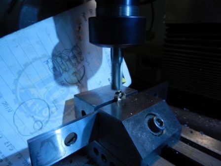
I'm thinking about mounting my Sherline lathe on the table of my Bridgeport mill and ruffling it out with a end mill.


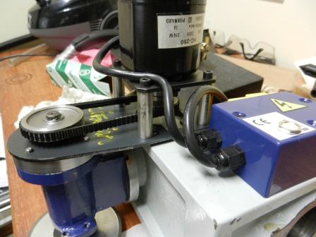
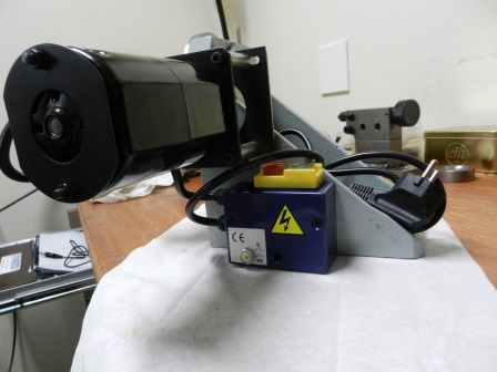
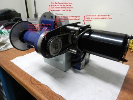
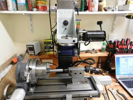
I will post this evening some photos of the machine with the "grinder device" and the modified tool post.
Thanks,
Edi
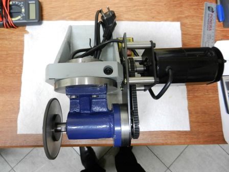
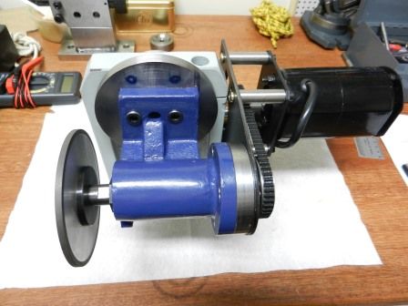
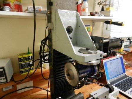
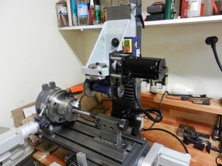
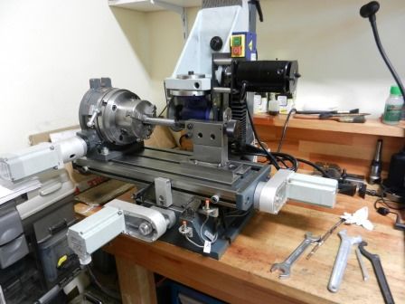
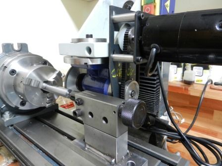
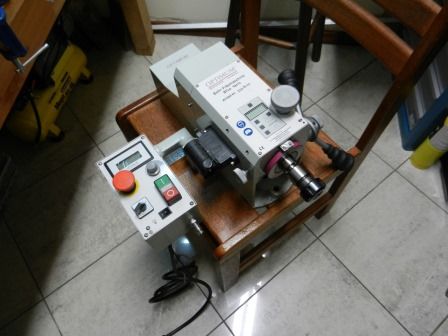
As I mentioned before, I would like to show you the result of a test I did for machining the crankshaft on the milling machine with cnc.
For a long time I was thinking how I would machine the crankshaft without having many failures. A couple years ago I saw a video showing a six cylinder model engine crankshaft being machined o a milling machine, then I thought I could use my CNC milling machine to do the job, at least to do the rough job, leaving material for final the pass on the lathe or on a grinding machine.
Here is the video I`m referring to.
http://www.youtube.com/watch?v=NV1ZOzAaXbo
As you can see on the video the blank was fixed on the dividing head (I think it is a rotary table on vertical position) with a device. For the pin throw, the device was moved of center and the milling head (z axis) was fixed.
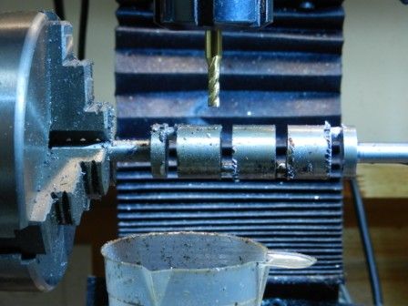
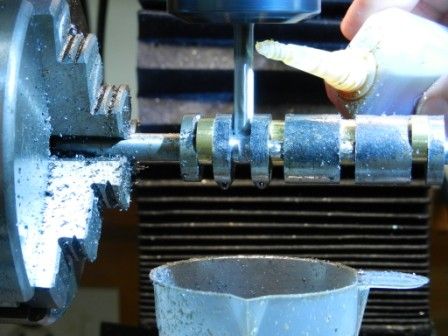
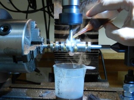
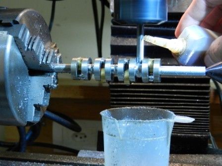
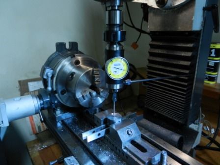
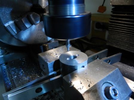
My idea was little different. I wanted to use the CNC resources I had on hand generating a G code that would move the machine head with the blank fixed on the center of the dividing head (circular interpolation) but using the Z axis.
I use the Mastercam Software to generate my G codes. With the help of my Mastercam teacher *discussion*, we produced some tests shown on the videos bellow.
I was right about my idea. The test worked fine Thm: only need some fine adjustments to eliminate unnecessary movements.
In order to avoid any "probably" damage to the machine or to the tool caused by a mistake, I run the test on a wooden blank.
First video shows the center bearing being machined. As the width of the bearing is 5.59mm and I used a 4mm end mill it was necessary 2 passes.
http://youtu.be/CwQQ9UtWpCE
The second video shows the crank pin being machined. Observe the movement of the Z axis.
http://youtu.be/w95zgWEtOkU
I`m really happy with the result, now I can start machining the real crankshaft on a 01 steel blank.
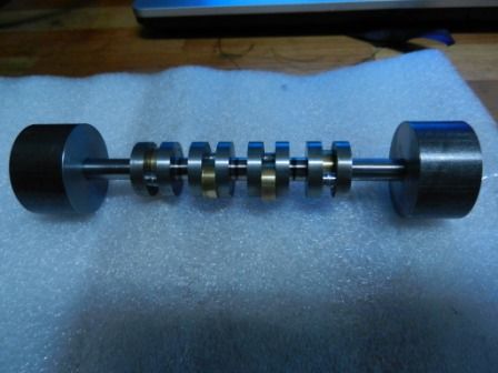
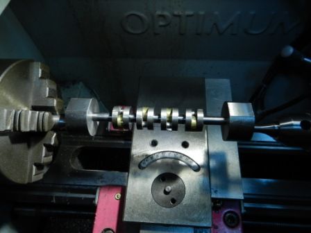
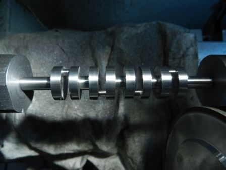
I also used the same idea to machine the camshaft. It also worked fine. I don’t have the video because I screwed the blank due to a mistake :wall:*club* on zeroing the axis. I did a second test but no video was generated.
When machining the real camshaft I will make a video.
Well, one more step reached in direction to a running engine "I hope"
Thanks for watching and I hope you liked this.
Edi
Hi, My name is Deepak. I am from India. I would like to the the plans for your inline 4 engine.
Plz email me.
Cheers Deepak
