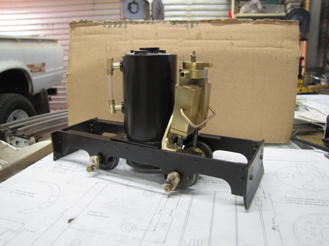
Building Fred

Home Model Engine Machinist Forum

Help Support Home Model Engine Machinist Forum:

This site may earn a commission from merchant affiliate links, including eBay, Amazon, and others.
Well, Saturday turned into a no-shop day for me, so I got an early start this morning.

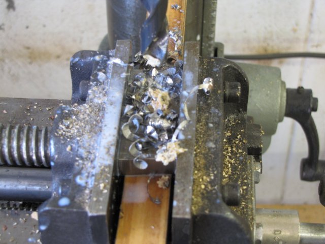
First up was a new stand for the pump. This stainless steel is a bit of a challenge to work; I found that wit LOTS of synthetic oil/water coolant and aggressive feed it works well. First I drilled a 5mm pilot hole, then the plunged the 12mm drill bit through at lowest speed on my drill press (220RPM). A photo after I finished drilling the 12mm hole for the pump body in the new block; the white puddles is the coolant:
normal_IMG_0374.JPG


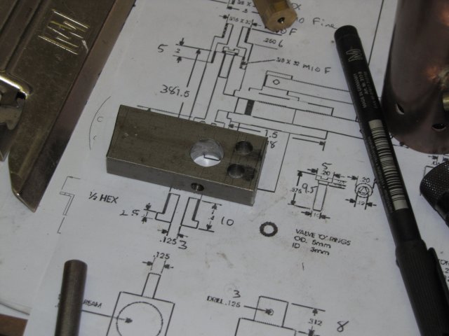
I also drilled out holes for the top link mounting, and a 5mm hole on the side for threading M6 for a grub screw to hold the pump cylinder in place. My bandsaw didn't like the stainless very much either; normally it cuts pretty square, but at the top and bottom of the piece you can see how the cut ran off at an angle when I cut the block from bar:
normal_IMG_0375.JPG


After that I hacksawed most of the excess metal off around the link connection, and milled away the rest; slowest high-range speed on the Myford, once again with lots of coolant. This time things worked out ;D. I turned the base of the stand square with the 4-jaw - and the stand was finished. Some brass plate and bar was sawn and filed to shape for the handle and linkages, stainless steel pins turned up and threaded, and a new brass fork for the piston-handle connection made. No photos; I got too busy and was working at a good clip.

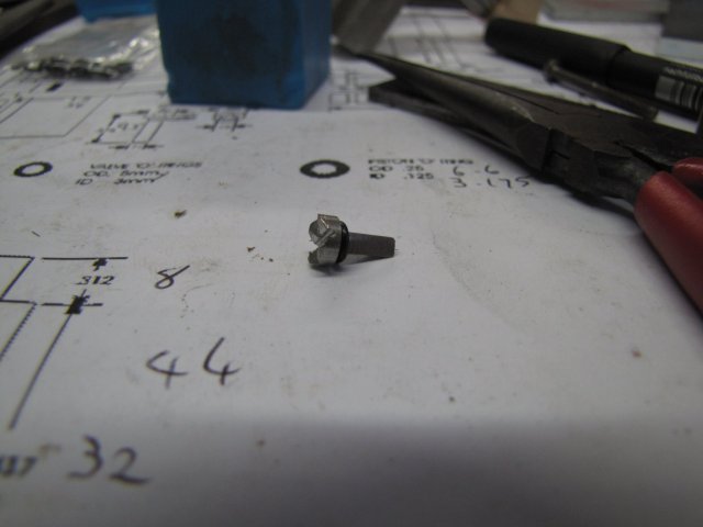
Next up was the 2 valves, also from stainless rod; simple turning job with the collet chuck, and then using 3 marks in the collet nut as "basic indexing" and some filing with a small flat file; three flats on each valve. Parted off, and clamped in toolmaker's clamp then in big vice, and used a hacksaw to cut 2 grooves on the top of each valve; then some more filing for additional clearance on the valve top. A photo of one of the finished valves:
normal_IMG_0391.JPG


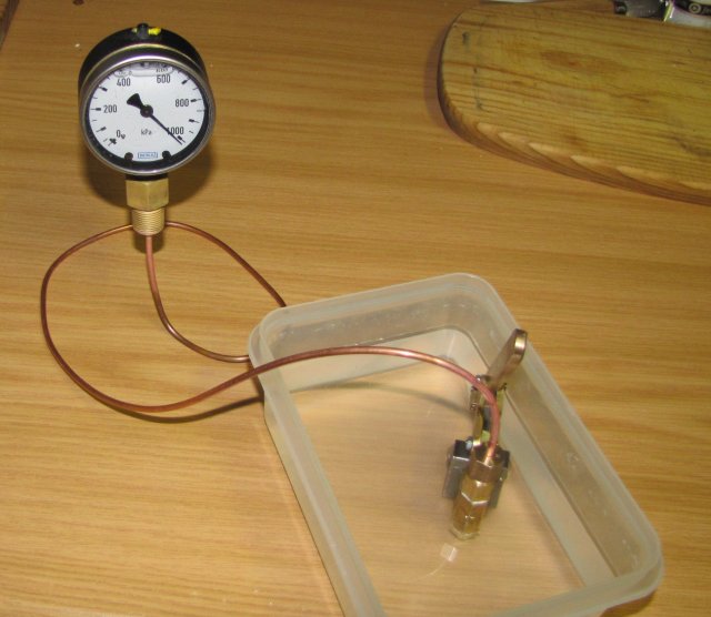
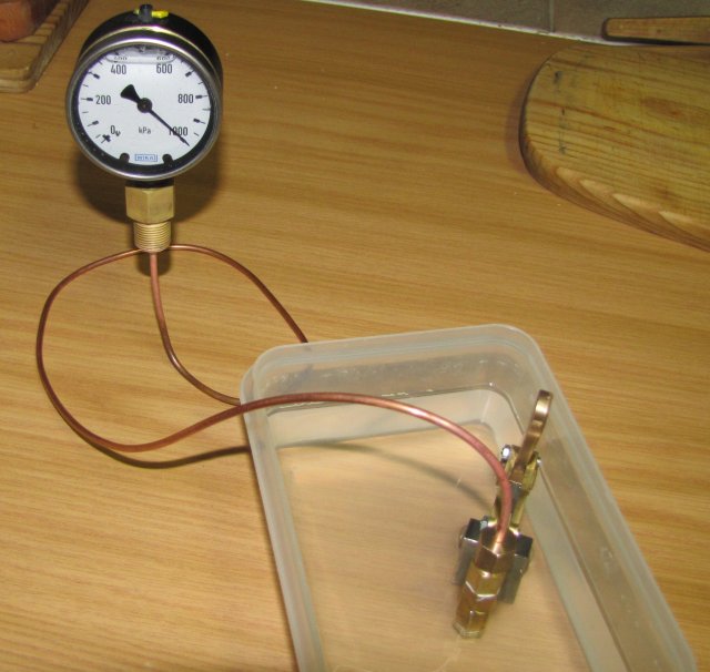
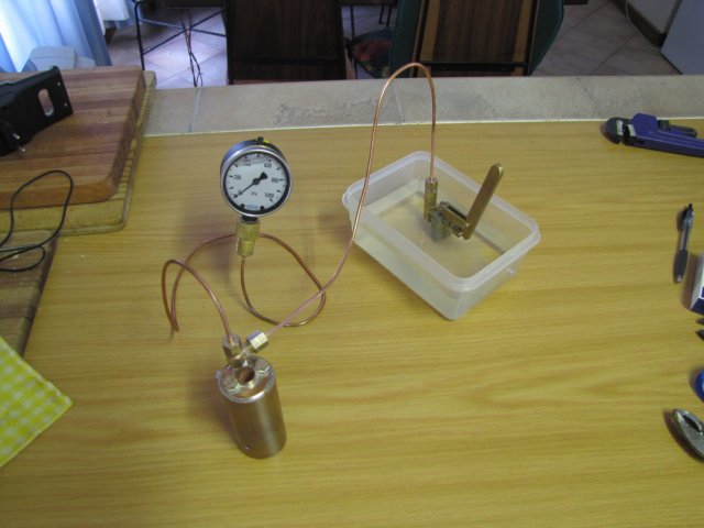
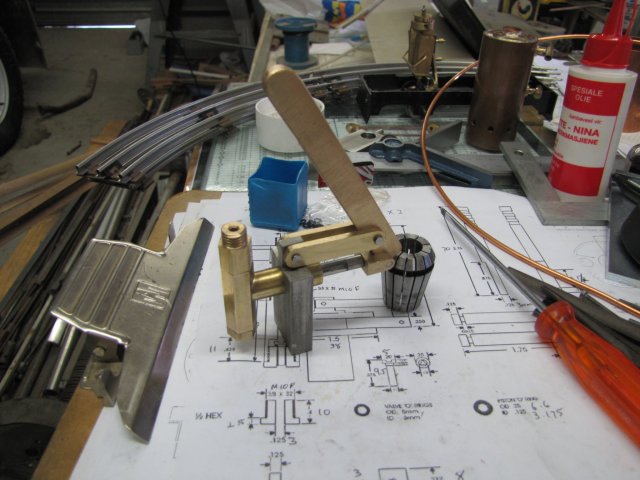
A quick assembly of the lot and a test in a bowl of water and it pumps ;D - I don't know to what pressure yet, as I still have to do some plumbing work for that, but was out of time for today:
normal_IMG_0398.JPG


I'll most likely be quiet until next Saturday, as I'm flying to Johannesburg tomorrow for a week-long course, with very limited - if any - Internet connectivity.

Regards, Arnold
 
Just look at that last picture....man oh man...

train tracks...a boiler...a pump...part of a loco...

Have a good trip.
 
Good job on the pump, Arnold. It looks good, and appears to be a sturdy unit.
Hopefully, you'll get lots of use from it. : )

Dean
 
Zee, Dean, thank you :)

Thanks Zee ;), I just wish the track I had was the full "deluxe" track set I ordered & not the "figure 8 expansion pack" I was sent... In that photo, you can see ALL of the track I have, except for a crossing piece. If I did have the lot, I'd have horrified everybody with a loop around the track with the loco body running on compressed air ;D - for now, it looks like it's first runs will have to happen on a straight line made from wooden 1/4 rounds... (I am - to put it EXTREMELY politely - "Annoyed" with the people from trainz.com...)
And thanks, I'll try and have a good trip :)

Dean, thank you; I hope so too; it does not look as good as I wanted, but for now it's function over looks :)

Kind regards, Arnold
 
A bit more progress on Fred.

This afternoon I silver soldered a piece of copper pipe to the adapter I have for the pressure gauge, turned up an olive and nut to match the pump connection, and tested the lot. Had to do that in the kitchen, as there is no open flat space available in the workshop :hDe: - I'll have to tidy up a bit...

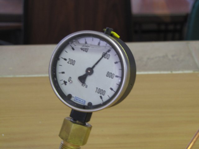
The pump works well; easily (and nearly too quickly!) went up to 150psi:
normal_img402e.jpg


An hour later, a very small loss of pressure, but I think this is OK:
normal_img403e.jpg

I played around with the setup a bit; releasing and re-pressurizing a couple of times, and will now leave it under pressure overnight to see what happens...

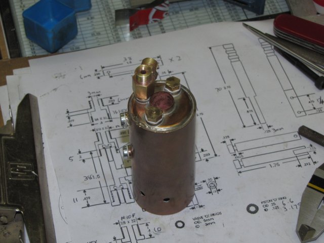
I also made up some plugs for the connections on the boiler, as well as a t-piece to connect the pump and gauge to it. Tomorrow I just need to make two nuts and olives, and fit that to a piece of pipe to give the boiler a pressure test:
normal_IMG_0405.JPG


Regards, Arnold
 
Hi Arnold.

The pump looks great and works well. I have used mine to test 2 boilers so far and I'm sure it will test many more. Well done.

Cheers

Rich
 
Been following this build all along and it's looking good, Arnold. If you don't like the pressure loss and you think it might be the check valves, you can always put a valve after the pump to close after you pump it up. I worked for an excavation contractor and we would put in water and sewer pipes that had to be pressure tested to 100 or 150 psi for 30-45 minutes. The pump was basically the same as yours only scaled up about 4X. We always closed that extra valve just to make sure any loss wasn't through the check valves. It was faster and cheaper that way.
 
Yeah, what Jared says.. my plunger pump leaks pretty badly so I have a valve to shut it off once I'm up to pressure. It's amazing how quick it comes up, isn't it.

I've considered inserting a Goodall-style check valve made from a bit of silicone tubing-- that should be pretty leak resistant at 100 PSI.
 
shred said:
I've considered inserting a Goodall-style check valve made from a bit of silicone tubing-- that should be pretty leak resistant at 100 PSI.
No kidding! I tested my Cracker boilers with the Goodalls in place and didn't get squirted at 150PSI like I was expecting. Good idea for a quick check valve! :bow:
 
Looks like you're all ready to test the boiler, Arnold. Good going!

What's an olive in this application? Same thing as a ferrule, like a small compression fitting?

And.. I know what the eating kind of olive is, for all you wise owls just about to pounce on your keyboards!

Dean
 
Rob, Thanks very much Mate ;D

Rich, thank you very much :) - and thank you for the design - works a treat!

Jared, Shred, Vernon, thank you for your input :) - I nearly made an extra valve but things worked out OK for now. Never heard of a Goodall valve; a search brought up that it is basically just a valve made using a bit of silicone tubing to block two cross-drilled holes connected to a center hole ? - sort of like a "round" Reed valve ? - filed away for future reference as it can be very useful!

Dean, thank you :D - I'm not sure if the two are the same. In my application, the olive is soldered to the pipe, whereas I think ferrules are commonly used in plumbing to use connectors to crimp them down around the pipes. Could be the same thing though, and I might have the cat by the tail :big:. Hmmmm Olives.... I feel like something Mediterranean tonight ;)

I had a very good day bar one DUH moment today; rain this morning to keep things cool, my team won the Dakar, and progress on Fred ;D

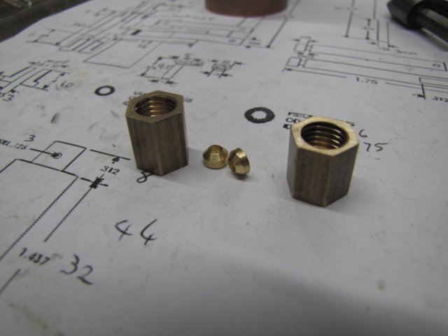
First thing this morning I made some olives and nuts for more plumbing:
normal_IMG_0409.JPG


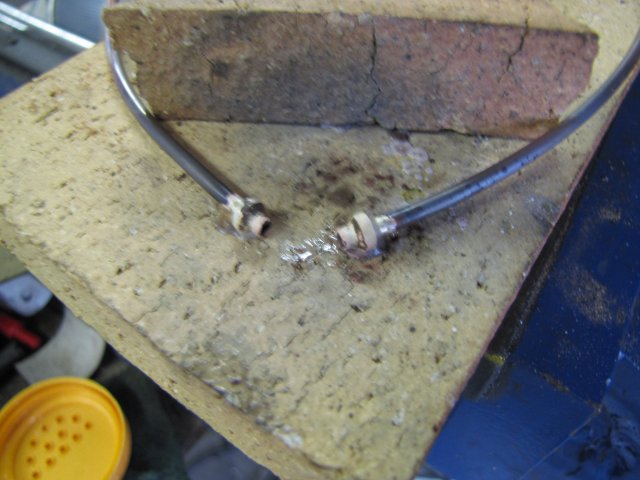
Silver soldered the olives to a length of copper pipe (AFTER I put the nuts on the pipe and made sure everything was right way around). I just looped the pipe around the back of the vertical fire brick to get the ends close together for soldering:
normal_IMG_0410.JPG


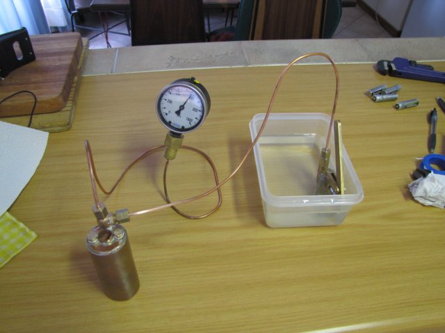
Then back to the kitchen for the tests; all filled up with water and plugged to test:
normal_IMG_0412.JPG


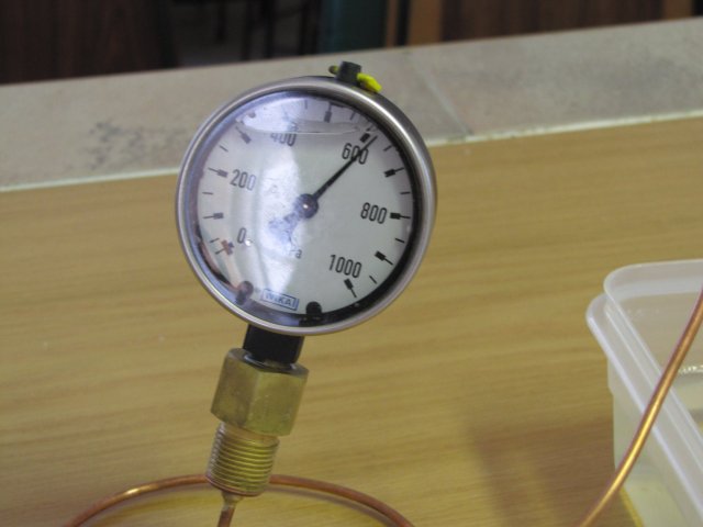
First up, slowly brought the pressure up to 550 kPa; that's close enough to 80 psi:
normal_IMG_0413.JPG


Then I loosened the connection nut on the top of the pump to relieve the pressure, tightened the nut, and brought things back up to pressure again. This was for a bit of a stress-test. I overshot the pressure a bit - went to about 610kPa (~90psi), but that's OK:
normal_IMG_0415.JPG


An hour later, a very slight drop in pressure, but that was about the same as I had with the guage only. And no leaks at all on the boiler ;D:
normal_IMG_0416.JPG


I consider the boiler safe to use now; the pressure tests were slightly more than double the designed maximum pressure of 40 psi, and from the engine tests, it might have to normally run at at only 20 psi or so. So the boiler needs a way to mount on the locomotive. As I deviated from the original plans, I had to figure out a new way of mounting it. I decided on a circular flange that can be bolted to the frame with four 2mm screws, so next up, I started on the flange.

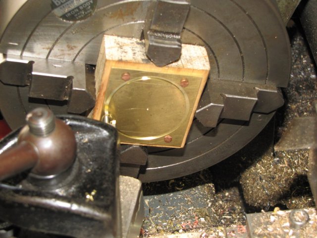
I marked up a piece of brass plate, and then puzzled on how to cut the hole for the boiler in it. I don't have a trepanning tool or a suitable hole saw. So I settled on a block of wood for a mounting surface, and nailed the plate to it through the mounting holes (which I had already drilled). Nails, because I don't have suitable small screws in stock. Mounted the lot in the 4-jaw and centered everything. I would have liked tailstock support to keep the center cut-out in place, but could not get the tailstock center past the top slide... So I went without, and VERY carefully cut the hole - Slow speed and very fine feed indeed; as that center disk was going to come out running, with sharp edges... While reviewing the photos for this post I had the DUH :Doh: :Doh: moment; I could just have screwed the center part to the wood block as well!! - so a photo on how NOT to do it:
normal_IMG_0419.JPG


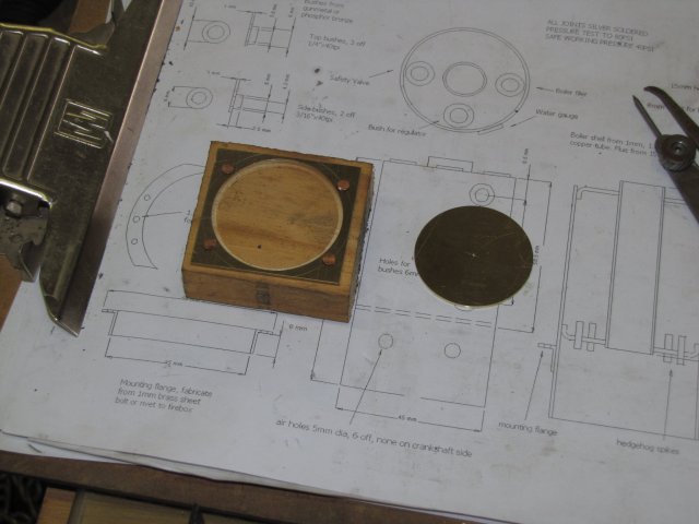
Things turned out OK though:
normal_IMG_0421.JPG


The flange was a press-fit over the boiler; I needed to use a hammer and a bearing outer shell for support to tap it into place on the boiler. Not wanting to bring the boiler to silver soldering temperature again, I soft-soldered the flange in place; there is no pressure involved, and the boiler should never reach the melting point of the soft solder; this is just a precaution, as the flange is already a press fit and should not move.

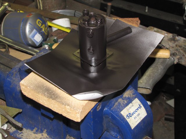
After soldering on the flange, I scrubbed the boiler with some scotch-brite and gave it a rub-down with acetone, then sprayed it with high temperature black paint - after covering all the mounting flanges again:
normal_IMG_0423.JPG


I couldn't resist a mock-up assembly of the parts so far ;D :
normal_IMG_0429.JPG


Some more plumbing required... The regulator and oiler (as well as the missing water gauge glass nuts) up next. Darn... The weekend's over...

Regards, Arnold
 
Hi Arnold

Fred is looking stunning Thm: , i am pleased the boiler test went OK , :bow: :bow: :bow: :bow: :bow: :bow:


Great job ,regards Rob
 
great progress in this week end arnold!
the boiler is very nice, and your test has proved that it is very strong too :)

Fred is proceeding fast and well, carry on arnold
 
Hi Arnold

Thats looking superb,


I bet you couldn't resist giving it a little push and going choo choo.

woohoo1 woohoo1

I know I couldn't:- :big: :big: :big: :big: :big: :big:

Great work enjoying your build.

Have fun

Stew
 
Arnold,

Great work man. :bow:

In Oz Olives come in Copper and Nylon and are used mostly by plumbers. They are not soldered to the pipe. Nylon for cold and lower pressures, Copper for hot and higher pressures. Ferrules are a slightly different system and are used on such things as condenser tube plates where the ferrule is screwed into the tube plate, using a slotted T spanner, with fibrous packing behind it, allowing for expansion and contraction of the tube(s). The 3rd way was originally to upset the end of the copper pipe to form a bulge against which the the mating male and female fittings locked to form a seal. This was later superseded by a bronze ring soldered to the pipe about one pipe diameter from the end and works in exactly the same way as the upsetting of the pipe.

This information is contained in "Bob's Glossary of Useless Knowledge," (has restricted access coz it's easy to get lost in there ;D)

Best Regards
Bob
 
I like your assembly shots, Arnold. It keeps us on the hook.
Good results on the boiler test. It's ready when you are!

Thanks for pictures of the olives.
The compression fitting I mentioned that we use here (US) looks somewhat similar, but has the same bevel on each end, and is swaged onto the copper tubing when the two mating surfaces are squeezed together by opposing nuts, (fittings).
The other thing Bob mentioned is used here too, we call flaring, or a flare fitting. The end of the tube is formed by a mandrel, resulting in a flare shape that matches the surface of another pipe fitting.
I guess we use the same stuff, but different.

Dean

 
Deanofid said:
The other thing Bob mentioned is used here too, called flaring, or a flare fitting. The end of the tube is formed by a mandrel, resulting in a flare shape that matches the surface of another pipe fitting.
I guess we use the same stuff, but different.

Dean

Actually that's No4. and I had forgotten to mention it - another senior moment, as I said you can get lost in there. ::)

Best Regards
Bob
 
Rob, Ariz, Vernon, Stew, Bob& Dean, thank you very much :)

Stew, yes, I was going Choo Choo - how did you guess ? :big:

Bob, thank you; technical information is never useless :) -

Dean, thanks for the reminder on the flaring; I actually have two pipe flaring tools - metric and imperial - never used them though... Hmmm... Chimney will need a flare...

Kind regards, Arnold
 
Back
Top