You are using an out of date browser. It may not display this or other websites correctly.
You should upgrade or use an alternative browser.
You should upgrade or use an alternative browser.
Building Fred
- Thread starter arnoldb
- Start date

Help Support Home Model Engine Machinist Forum:
This site may earn a commission from merchant affiliate
links, including eBay, Amazon, and others.
zeeprogrammer
Well-Known Member
- Joined
- Mar 14, 2009
- Messages
- 3,362
- Reaction score
- 13
Awesome Arnold. Just awesome. A very productive day.
Really good, Arnold!
I wondered how you would make out with the copper. Looks like you have it knocked!
Just point of interest, or, maybe not. I've used whole milk on copper in the past on advise of a old machinist friend. Worked pretty well, but needs a good clean up or you'll have a smelly shop in warm weather.
So, here's a question from a guy who's never built this type of boiler; What are hedgehog pins, and their purpose?
Keep up the good work. Fred is really taking shape!
Dean
R
RobWilson
Guest
WOW Arnold
Great job Thm: you are really going for it :bow: :bow: :bow: :bow: :bow: :bow: :bow:
Regards Rob
Great job Thm: you are really going for it :bow: :bow: :bow: :bow: :bow: :bow: :bow:
Regards Rob

$29.95
Competition Engine Building: Advanced Engine Design and Assembly Techniques (Pro Series)
Amazon.com Services LLC
![DreamPlan Home Design and Landscaping Software Free for Windows [PC Download]](https://m.media-amazon.com/images/I/51kvZH2dVLL._SL500_.jpg)
$0.00
DreamPlan Home Design and Landscaping Software Free for Windows [PC Download]
Amazon.com Services LLC

$99.99
AHS Outdoor Wood Boiler Yearly Maintenance Kit with Water Treatment - ProTech 300 & Test Kit
Alternative Heating & Supplies

$94.99
$109.99
AHS Woodmaster 4400 Maintenance Kit for Outdoor Wood Boiler Treatment
Alternative Heating & Supplies

$40.02
$49.99
Becker CAD 12 3D - professional CAD software for 2D + 3D design and modelling - for 3 PCs - 100% compatible with AutoCAD
momox Shop

$39.99
$49.99
Sunnytech Low Temperature Stirling Engine Motor Steam Heat Education Model Toy Kit For mechanical skills (LT001)
stirlingtechonline

$45.99
Sunnytech Mini Hot Air Stirling Engine Motor Model Educational Toy Kits Electricity HA001
stirlingtechonline

$89.99
Outdoor Wood Boiler Water Treatment Rust Inhibitor- AmTech 300 & Test Kit
Alternative Heating & Supplies

$24.99
$34.99
Bowl Sander Tool Kit w/Dual Bearing Head & Hardwood Handle | 42PC Wood Sander Set | 2" Hook & Loop Sanding Disc Sandpaper Assortment | 1/4" Mandrel Bowl Sander for Woodturning | Wood Lathe Tools
Peachtree Woodworking Supply Inc

$519.19
$699.00
FoxAlien Masuter Pro CNC Router Machine, Upgraded 3-Axis Engraving All-Metal Milling Machine for Wood Acrylic MDF Nylon Carving Cutting
FoxAlien Official
ToniTD1490
Active Member
- Joined
- Feb 4, 2009
- Messages
- 31
- Reaction score
- 1
Hi Arnold
My apology with my English. Very good work. I have learnt a lot of with this thread, the idea of making your own rivets , did you anneal before to put them? I should like to see the jig to extend the jaws in your hack saw, any pictures and details please? I have the same problem with mine and your jig is very ingenious. As say here FANTASTICO!
Regards
ToniTD1490
arnoldb
Well-Known Member
- Joined
- Apr 8, 2009
- Messages
- 1,792
- Reaction score
- 12
Gordon, Nick, Zee, Ron, Dean, Rob, GBritnell, Stew, ToniTD1490 and Ariz - thank you very much for your positive reponses 
Dean, I've also heard about the milk from various sources, but like you said, I'm not about to try that - with the last couple of days giving me 35 deg C and above in the shop, the milk would be liable to curdle while applying .
.
The hedgehog pins effectively raise the effective heating surface area for the boiler and are also more effective for heat transfer to the water in the boiler. I saw in Firebird's build that he called them thermal conduction pins.
GBritnell - thank you; and a question from my side - if you don't mind. Would the engine run better on steam because of steam expansion in the cylinders?
ToniTD1490, no worries about your English . I didn't anneal the copper wire for the rivets; as it comes out of the cabling that I used, it is already soft. Annealing it before use wouldn't do any harm though. I added the modifications to my saw at the end of this post
On to today's work. One thing I have learned from my limited silver soldering endeavors is that I'm inclined to use too much solder, so one goal for today was to hold back a bit.
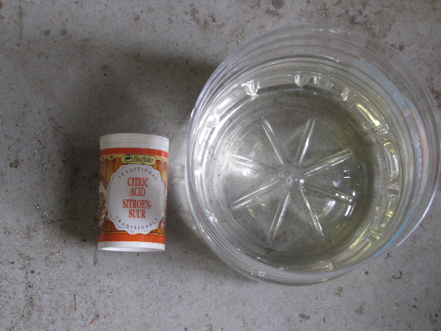
A lot of pickling would be needed, so I made up a citric acid pickle bath from an empty 5L plastic mineral water bottle:
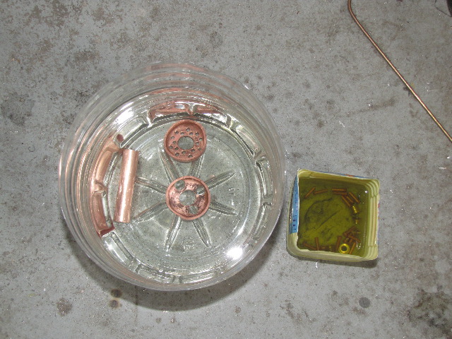
Most parts dumped in the pickle - the small yellow container has the bushes and copper rivets I intend to use for the conduction pins:
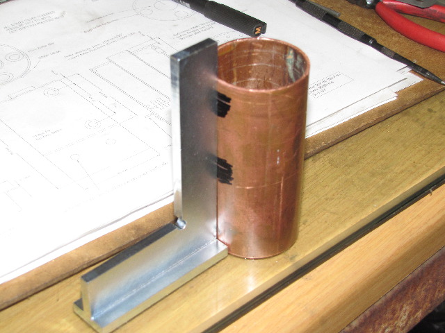
While those were in the bath, I laid out the boiler shell for the water gauge holes, and the air ventilation holes - here I'm getting the gauge holes nicely in line with a new "backed" square I bought a couple of weeks ago:
After drilling the needed holes in the shell, I added that to the pickle as well. The bottom cap and copper rivets looked good, so I assembled the lot with flux:
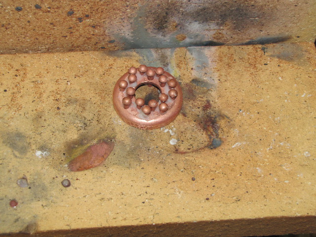
Soldered - I used a smallish butane torch, not the Oxy-Butane set, and just quick light touches of the solder rod to the joints - got better while working:
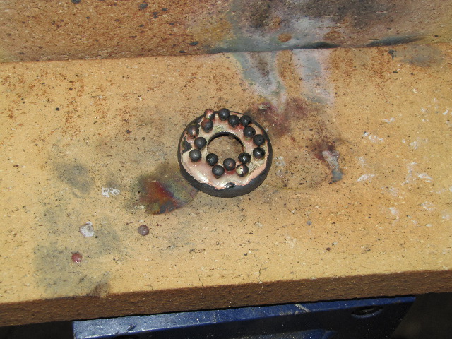
I only took time to take the photo, and then dumped the cap stright back into the pickle; a bit of steam and bubbling, but most of the black stuff & flux came off straight away.
Same treatment followed for the top cap and bushes - I drew pencil lines about one mm away around the bushes as a test. Worked OK except for the spot where I accidentally touched the rod on the cab between the bushes... :
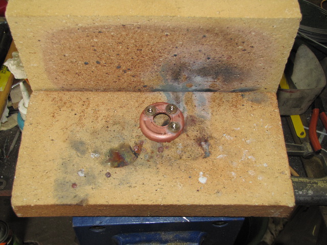

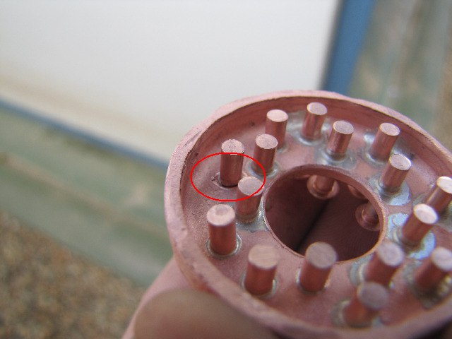
The bottom cap was lying in the pickle while I did the above; when I touched it, some of the black that was left came off, so I fetched a retired clean toothbrush, and just scrubbed at it a bit and it was nice & clean in no time. On closer inspection, there was just one pin that was not soldered properly, so I just added flux to it on both sides, re-heated the lot and gave it a quick dab again. Photo of the "dry joint":
Next up, it was the bushes for the gauge glass on the boiler shell - the pin keeping alignment is a length of stainless steel rod:
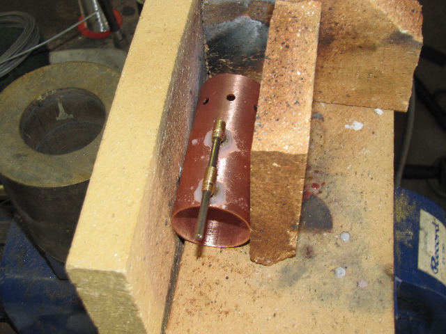
The butane torch had a really hard time of getting everything to temperature for this, even though I tried to get as much heat containment as possible... At one point - just as everything started reaching solder temperature, the torch went out. So I let things cool a bit, added more flux and started again. Eventually got the job done adequately, but not good looking.
I also soldered the center flue to the bottom end cap; it is easier to do this before final assembly, as I had the opportunity to check it and the end cap for a good seal. Tonight the parts will spend in the pickle; hopefully I can get a couple of minutes of shop time tomorrow after work to finish off. I'll definitely use the butane torch in combination with the oxy-butane set - butane torch for as much global heat as possible, and the oxy set to add spot heat for the final soldering; there is a lot of parts that will require heat...
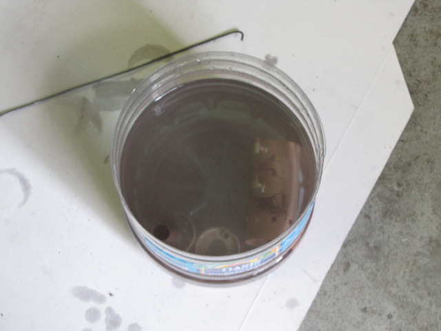
The pickle got a good work-out today - not nice & clean any more!:
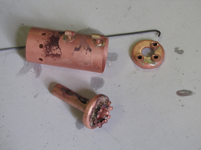
And the boiler parts so far:
Regards, Arnold
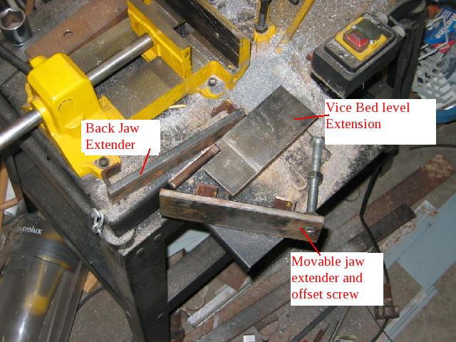
Bandsaw modifications for ToniTD1490:
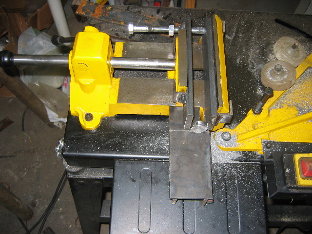
The "extended jaws" are just made up from 60mmx10mm flat bar. The hooks that clip on to the existing vice jaws are short bits of 25mm angle iron shortened on one end to fit the existing vice jaws - I welded these on to the flat bar while mounted and clamped on the saw with pieces of thin plate in between to give a bit of spacing for a "loose" fit.
The vice bed extension is built from a piece of 6mm plate, with 2 pieces of flat bar welded to the bottom to give the exact same height as the vice bed above the saw table. The piece of round bar welded to this assembly goes into the hole in the saw that is used for the distance piece - to keep it fixed in place.
The bolt for setting spacing is an ordinary M14 bolt I had laying around, with a clearance hole and the nut welded to the back jaw.
To cut the blade groove, I just set the switch cut-off stop for the saw switch lower, as well as adjusted the head stop lower. Then I let the machine saw it's own groove in the bottom plate, which I then slightly widened it with an angle grinder. If you don't do this, the saw might break blades when it finishes cuts. After done, the cut-off switch and head stop was put back to "normal".
I also used an angle grinder to grind away bits of the saw to be able to use it in (nearly!) upright position
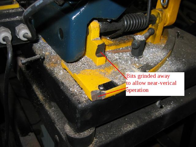
:-[ - "verical" in the above picture must be "vertical"!
If you have any more questions, feel free to ask
In use:

WOW - this post took me 2 hours to do! - Had to revise it twice because of new posts while I was typing up - Thanks Everyone! ;D
Dean, I've also heard about the milk from various sources, but like you said, I'm not about to try that - with the last couple of days giving me 35 deg C and above in the shop, the milk would be liable to curdle while applying
The hedgehog pins effectively raise the effective heating surface area for the boiler and are also more effective for heat transfer to the water in the boiler. I saw in Firebird's build that he called them thermal conduction pins.
GBritnell - thank you; and a question from my side - if you don't mind. Would the engine run better on steam because of steam expansion in the cylinders?
ToniTD1490, no worries about your English
On to today's work. One thing I have learned from my limited silver soldering endeavors is that I'm inclined to use too much solder, so one goal for today was to hold back a bit.
A lot of pickling would be needed, so I made up a citric acid pickle bath from an empty 5L plastic mineral water bottle:

Most parts dumped in the pickle - the small yellow container has the bushes and copper rivets I intend to use for the conduction pins:

While those were in the bath, I laid out the boiler shell for the water gauge holes, and the air ventilation holes - here I'm getting the gauge holes nicely in line with a new "backed" square I bought a couple of weeks ago:

After drilling the needed holes in the shell, I added that to the pickle as well. The bottom cap and copper rivets looked good, so I assembled the lot with flux:

Soldered - I used a smallish butane torch, not the Oxy-Butane set, and just quick light touches of the solder rod to the joints - got better while working:

I only took time to take the photo, and then dumped the cap stright back into the pickle; a bit of steam and bubbling, but most of the black stuff & flux came off straight away.
Same treatment followed for the top cap and bushes - I drew pencil lines about one mm away around the bushes as a test. Worked OK except for the spot where I accidentally touched the rod on the cab between the bushes... :


The bottom cap was lying in the pickle while I did the above; when I touched it, some of the black that was left came off, so I fetched a retired clean toothbrush, and just scrubbed at it a bit and it was nice & clean in no time. On closer inspection, there was just one pin that was not soldered properly, so I just added flux to it on both sides, re-heated the lot and gave it a quick dab again. Photo of the "dry joint":

Next up, it was the bushes for the gauge glass on the boiler shell - the pin keeping alignment is a length of stainless steel rod:

The butane torch had a really hard time of getting everything to temperature for this, even though I tried to get as much heat containment as possible... At one point - just as everything started reaching solder temperature, the torch went out. So I let things cool a bit, added more flux and started again. Eventually got the job done adequately, but not good looking.
I also soldered the center flue to the bottom end cap; it is easier to do this before final assembly, as I had the opportunity to check it and the end cap for a good seal. Tonight the parts will spend in the pickle; hopefully I can get a couple of minutes of shop time tomorrow after work to finish off. I'll definitely use the butane torch in combination with the oxy-butane set - butane torch for as much global heat as possible, and the oxy set to add spot heat for the final soldering; there is a lot of parts that will require heat...
The pickle got a good work-out today - not nice & clean any more!:

And the boiler parts so far:

Regards, Arnold
Bandsaw modifications for ToniTD1490:
The "extended jaws" are just made up from 60mmx10mm flat bar. The hooks that clip on to the existing vice jaws are short bits of 25mm angle iron shortened on one end to fit the existing vice jaws - I welded these on to the flat bar while mounted and clamped on the saw with pieces of thin plate in between to give a bit of spacing for a "loose" fit.
The vice bed extension is built from a piece of 6mm plate, with 2 pieces of flat bar welded to the bottom to give the exact same height as the vice bed above the saw table. The piece of round bar welded to this assembly goes into the hole in the saw that is used for the distance piece - to keep it fixed in place.
The bolt for setting spacing is an ordinary M14 bolt I had laying around, with a clearance hole and the nut welded to the back jaw.
To cut the blade groove, I just set the switch cut-off stop for the saw switch lower, as well as adjusted the head stop lower. Then I let the machine saw it's own groove in the bottom plate, which I then slightly widened it with an angle grinder. If you don't do this, the saw might break blades when it finishes cuts. After done, the cut-off switch and head stop was put back to "normal".

I also used an angle grinder to grind away bits of the saw to be able to use it in (nearly!) upright position

:-[ - "verical" in the above picture must be "vertical"!
If you have any more questions, feel free to ask
In use:


WOW - this post took me 2 hours to do! - Had to revise it twice because of new posts while I was typing up
zeeprogrammer
Well-Known Member
- Joined
- Mar 14, 2009
- Messages
- 3,362
- Reaction score
- 13
Another awesome post Arnold. This is great stuff.
ToniTD1490
Active Member
- Joined
- Feb 4, 2009
- Messages
- 31
- Reaction score
- 1
Arnold thanks for your prompt response, and quite very well explained, even the trick of widening the own groove the saw. I will try to adapt it to my band saw. I hope that 2 hours had been fun, I estimate very much the effort and the photos very explanatories. Regards,
ToniTD1490
ToniTD1490
More good progress, Arnold! I like this little boiler.
I've only made horizontal types, and plan on making a flue type pretty soon. This thread and Firebird's are a good source. (There's another flue build going on elsewhere on the forum too, but I can't remember where it is.)
Thanks for the porcupine, er.. hedgehog explanation.
; )
Dean
I've only made horizontal types, and plan on making a flue type pretty soon. This thread and Firebird's are a good source. (There's another flue build going on elsewhere on the forum too, but I can't remember where it is.)
Thanks for the porcupine, er.. hedgehog explanation.
; )
Dean
arnoldb
Well-Known Member
- Joined
- Apr 8, 2009
- Messages
- 1,792
- Reaction score
- 12
Zee, Thank you 
gbritnell, thank you very much for the clarification.
ToniTD1490, it's a pleasure. And I consider the time well spent
Thanks Dean - and sorry about the hedgehog/porcupine confusion; the hedgehog is the cute little one; the porcupine is the big one with attitude that you don't want to run into with a car... DAMHIKT
I finished soldering the boiler this afternoon after work. It came out OK with using the 2 torches. A photo of the set-up I used - the 2 torches, with the butane torch positioned to provide background heat, and mixed flux readily located should more be needed (which it was):
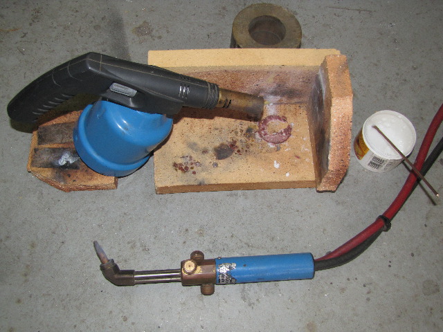
I assembled everything with flux paste in all the joints, and started heating to do the top first. Quite a bit of flux bubbled away from the joints while heating, so I added more. Then I fired up the other torch to a higher heat, and added it's heat; the flux flowed in short order. Running a circle with the high temp torch around the perimeter, I followed it with the solder rod; worked a treat. To solder the flue to the cap, I just pointed the hot torch flame down the flue, and the solder flowed easily around the joint.
Then I turned everything upside-down, added more flux to the bottom cap joint, brought to heat again, and once again ran a hot ring around the outside following with the solder.
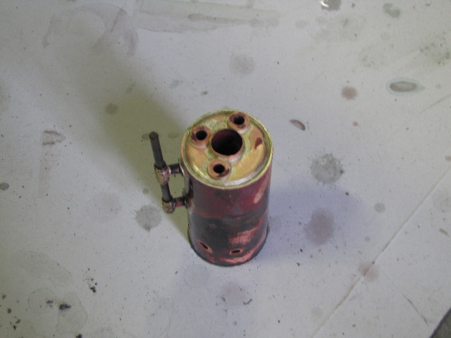
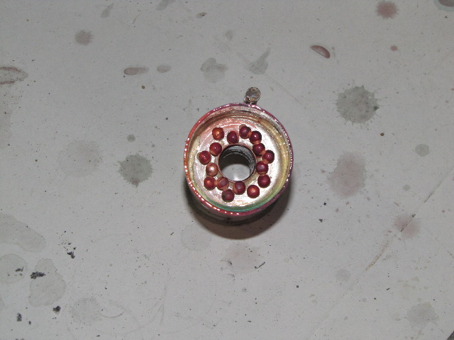
Two photos; top and bottom of boiler after soldering & quick dip in pickle - all the joints looks sound to me:
The parts can lay in the pickle now until tomorrow evening; then I'll just do a clean-up.
Next up will be a pump to do the hydraulic pressure test - I don't think that will happen this week or coming weekend though; shop time is limited in the evenings after work and I'll be out of town for some new year's celebrations for most of the weekend.
Regards, Arnold
gbritnell, thank you very much for the clarification.
ToniTD1490, it's a pleasure. And I consider the time well spent
Thanks Dean
I finished soldering the boiler this afternoon after work. It came out OK with using the 2 torches. A photo of the set-up I used - the 2 torches, with the butane torch positioned to provide background heat, and mixed flux readily located should more be needed (which it was):

I assembled everything with flux paste in all the joints, and started heating to do the top first. Quite a bit of flux bubbled away from the joints while heating, so I added more. Then I fired up the other torch to a higher heat, and added it's heat; the flux flowed in short order. Running a circle with the high temp torch around the perimeter, I followed it with the solder rod; worked a treat. To solder the flue to the cap, I just pointed the hot torch flame down the flue, and the solder flowed easily around the joint.
Then I turned everything upside-down, added more flux to the bottom cap joint, brought to heat again, and once again ran a hot ring around the outside following with the solder.
Two photos; top and bottom of boiler after soldering & quick dip in pickle - all the joints looks sound to me:


The parts can lay in the pickle now until tomorrow evening; then I'll just do a clean-up.
Next up will be a pump to do the hydraulic pressure test - I don't think that will happen this week or coming weekend though; shop time is limited in the evenings after work and I'll be out of town for some new year's celebrations for most of the weekend.
Regards, Arnold
zeeprogrammer
Well-Known Member
- Joined
- Mar 14, 2009
- Messages
- 3,362
- Reaction score
- 13
Congratulations Arnold. I bet you're feeling pretty good. I certainly would be.
I know virtually nothing about boilers...is the purpose of the rivets to provide more surface area for heat conduction? I have to admit I've been expecting to see a ball-peen. ;D
I know virtually nothing about boilers...is the purpose of the rivets to provide more surface area for heat conduction? I have to admit I've been expecting to see a ball-peen. ;D
You're moving along well, Arnold. Add me to the list of "boiler build watchers". I enjoy watching one come together.
You have porcupines in your neck of the woods, too? That's something we have here, along with opossum, badgers, wolverines, wolves, and other ornery critters. No hedgehogs, though. No hedges...
Dean
You have porcupines in your neck of the woods, too? That's something we have here, along with opossum, badgers, wolverines, wolves, and other ornery critters. No hedgehogs, though. No hedges...
Dean
Hi Arnold
I've just read your boiler build and think you are doing a great job. Copper is difficult to work with and takes some getting used to but practice makes perfect I'm told. After the build of my 2 boilers I feel confident enough now to tackle something bigger. If you will allow me offer one tip, get yourself a set of step drills, they drill perfect round holes in all types of thin plate. On boiler work drill the hole first then turn the bushes to fit. Keep up the good work. :bow: :bow: :bow:
Cheers
Rich


