
You are using an out of date browser. It may not display this or other websites correctly.
You should upgrade or use an alternative browser.
You should upgrade or use an alternative browser.
Brians Radial Engine
- Thread starter Brian Rupnow
- Start date


Help Support Home Model Engine Machinist Forum:
This site may earn a commission from merchant affiliate
links, including eBay, Amazon, and others.
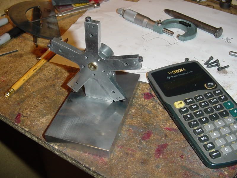
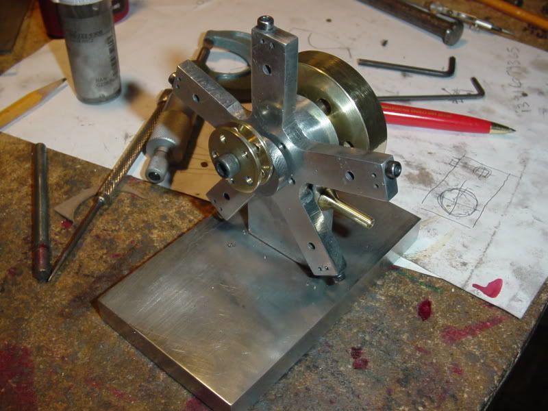
So---Now we have the main body finished and mounted and the center brass bushing in place. Its just mocked up for a picture right now. After lunch I have to do a little creative gasket making to keep air from leaking between the "star" and the vertical support. Then its time to start with my cylinders.
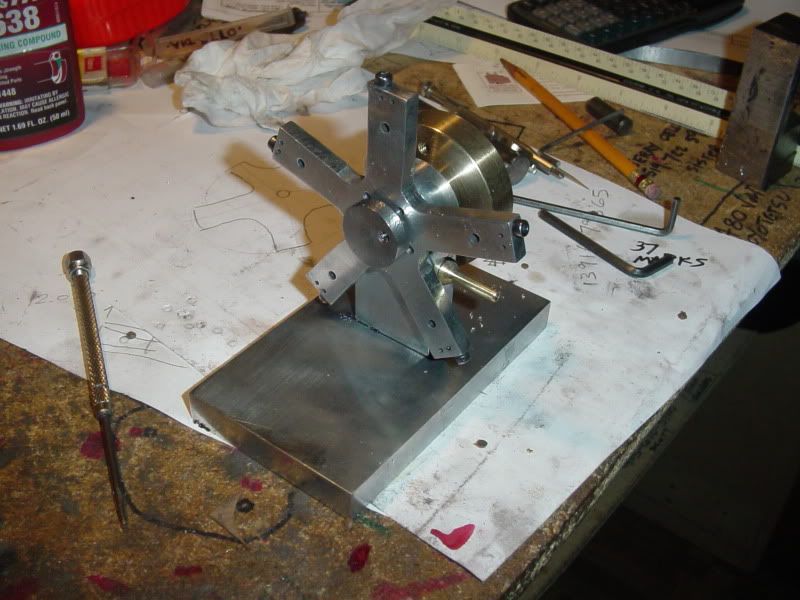
I spent this afternoon making and installing a gasket, machining an air inlet tube, the crankshaft, and a bronze flywheel. I machined the crankshaft from a solid peice of 7/8" diameter shaft, with the most of it turned down to 1/4" diameter. Why---well, partly because I'm a masochist, and partly because I don't know how much vibration there is going to be with this engine, and I didn't want a built up crankshaft flying apart. Interesting story about the peice of bronze that I used for a flywheel---my old neighbour gave it to me. He says he has had that peice of bronze since just after the Korean war. Apparently it was part of the guidance system in a torpedo?????? I also stopped by my metal supplier and picked up the material to make my cylinders and pistons and connecting rods from.---will start them tomorrow.
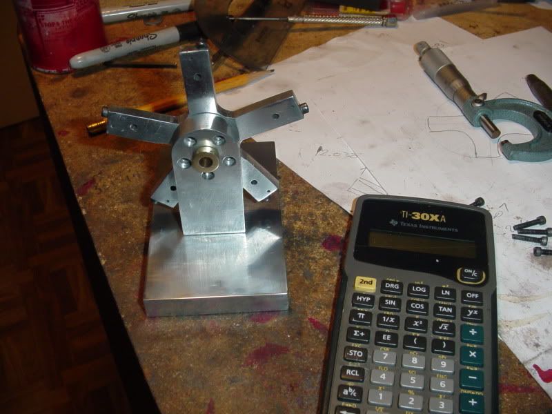
This morning I got up and machined the connecting rod hub. And yes, the one "master rod" will be siver soldered to this hub. Come on, talk to me people, if you are interested in this build. I feel like I'm posting in a vacuum here. I do intend to post all the detail drawings for this once its working.---Brian
Krown Kustoms
Well-Known Member
- Joined
- Aug 6, 2009
- Messages
- 313
- Reaction score
- 2
Looks good, I am still trying to figure out where I have seen this type of engine before.
I have seen it in person but cant remember where.
I haven't been to an engine show yet.
Does the center hub work as an eccentric?
-B-
I have seen it in person but cant remember where.
I haven't been to an engine show yet.
Does the center hub work as an eccentric?
-B-
- Joined
- Aug 25, 2007
- Messages
- 3,890
- Reaction score
- 715
Sorry for the silence, Brian. However, I always check out your progress first thing when I log on. And I do understand that a lot of our motivation for posting pictures is in the comments received.
I am amazed at how fast your projects proceed. I think the main difference between you and I is that you have a good set of working drawings before you begin and I kind of make mine up as I go along. My process is definitely slower than yours!
Does your cad software have the option for automatic ordinate distances? If I were drawing something like a radial engine, I would tend to use polar coordinates and angles from the center. Not sure how I would get that converted to x-y positions...
Chuck


$39.99
$49.99
Sunnytech Low Temperature Stirling Engine Motor Steam Heat Education Model Toy Kit For mechanical skills (LT001)
stirlingtechonline

$45.99
Sunnytech Mini Hot Air Stirling Engine Motor Model Educational Toy Kits Electricity HA001
stirlingtechonline


$12.56
$39.95
Complete Plans for Building Horse Barns Big and Small(3rd Edition)
ThriftBooks-Atlanta


$89.99
Outdoor Wood Boiler Water Treatment Rust Inhibitor- AmTech 300 & Test Kit
Alternative Heating & Supplies


$94.99
$109.99
AHS Woodmaster 4400 Maintenance Kit for Outdoor Wood Boiler Treatment
Alternative Heating & Supplies


$519.19
$699.00
FoxAlien Masuter Pro CNC Router Machine, Upgraded 3-Axis Engraving All-Metal Milling Machine for Wood Acrylic MDF Nylon Carving Cutting
FoxAlien Official


$40.02
$49.99
Becker CAD 12 3D - professional CAD software for 2D + 3D design and modelling - for 3 PCs - 100% compatible with AutoCAD
momox Shop


$99.99
AHS Outdoor Wood Boiler Yearly Maintenance Kit with Water Treatment - ProTech 300 & Test Kit
Alternative Heating & Supplies

![DreamPlan Home Design and Landscaping Software Free for Windows [PC Download]](https://m.media-amazon.com/images/I/51kvZH2dVLL._SL500_.jpg)
$0.00
DreamPlan Home Design and Landscaping Software Free for Windows [PC Download]
Amazon.com Services LLC


$29.95
Competition Engine Building: Advanced Engine Design and Assembly Techniques (Pro Series)
Amazon.com Services LLC


$24.99
$34.99
Bowl Sander Tool Kit w/Dual Bearing Head & Hardwood Handle | 42PC Wood Sander Set | 2" Hook & Loop Sanding Disc Sandpaper Assortment | 1/4" Mandrel Bowl Sander for Woodturning | Wood Lathe Tools
Peachtree Woodworking Supply Inc


![MeshMagic 3D Free 3D Modeling Software [Download]](https://m.media-amazon.com/images/I/B1U+p8ewjGS._SL500_.png)

Krown Kustoms---Many older propellor type aircraft had radial engines. The hub is not an eccentric--the ecentric is at the end of the crankshaft. The hub orbits --its very difficult to explain. Look at my animation post that says "Damn---I think I can make this work". Chuck---You are so right!!! It is the dialogue with all the other people out there that makes this fun and keeps me motivated. When nobody answeres my posts, I start to feel like nobody is interested. When I make drawings I can choose whatever type of dimensions I want to use. There is an "automatic" dimensioning sequence I can choose, but it puts so many dimensions on the drawing that I could go crazy looking at them all. All I have to do is select where I want the dimensions to appear, between which edges, and the software puts them there, one at a time. That way I have control over what type of dimensions are used and where they go. Since I "grew up on a drafting board", and only moved into computer world about 12 years ago, I tend to use a combination of outline dimensions and ordinate dimensions. As far as how fast I do things---Thats only because I have no real work these days, so I can work 8 hours a day on this stuff. If the friggin economy ever comes back, I'll probably be so busy doing "real" work that I will have no time to build model engines.----Brian
- Joined
- Dec 2, 2008
- Messages
- 971
- Reaction score
- 9
Brian
It looks like you are heading down the right track. That engine ought to run just fine. I like the change from staggered pistons with individual connection to the crank to the hub with master rod. I have looked at the staggered design in the past and it just didn't look good to me. I like symmetry.
Will the valve positions for the cylinders all be the same? I haven't plotted it out but it seems that the cylinders with the free connection might have a slightly greater wobble angle than the one with the master rod. Even if they do, it may not make any difference to the port positions.
Keep it up. I want to see that hub spin. Most radial engines hide all that action in the crankcase.
Jerry
black85vette
Well-Known Member
- Joined
- Jan 18, 2009
- Messages
- 1,084
- Reaction score
- 25
Good stuff Brian. Lot's of us watch the project with great interest, but may not have much to add. Had a guy on one of my Corvette forums that responded to every post he read. But most of his posts were just ") or Thm: I think he had a total number of posts around 25,000.
or Thm: I think he had a total number of posts around 25,000.
I also wonder about the timing with a master rod. Does it make the other cylinders time a little different? I assume your software models this and places the ports appropriately. Is that right?
or Thm: I think he had a total number of posts around 25,000.I also wonder about the timing with a master rod. Does it make the other cylinders time a little different? I assume your software models this and places the ports appropriately. Is that right?
Thanks for the responses guys. As far as the port timing, My solid model tells me that either there is no difference between the master rod timing and the other 4 cylinders, or else so little difference that it shouldn't make any difference. I won't really know myself untill I go to run this thing.
tel
Well-Known Member
- Joined
- Feb 8, 2008
- Messages
- 3,293
- Reaction score
- 45
Brian Rupnow said:When nobody answeres my posts, I start to feel like nobody is interested.
I'm watching with interest Brian, but, so far, nothing really to add.
- Joined
- Jun 4, 2008
- Messages
- 3,294
- Reaction score
- 636
Since I am working on the Halo engine, also a 5-cylinder radial, I have been following this build as well. The Halo has fixed cylinders with pushrod valves operated by cams, so quite different in design.
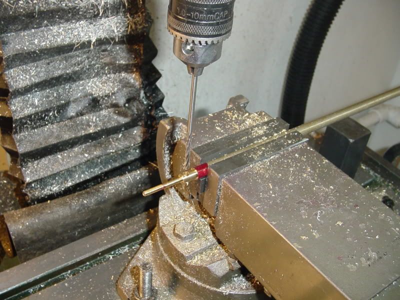
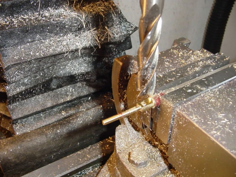
This afternoon wasn't as productive as I would have liked. First off, I thought my mill was out of tram. After multiple checks, I established that my mill table is in perfect tram, but my (cheesy) tilt/twirl/swivel vice is out of tram by 1 thou from right to left over the width of the 3" jaws. I decided that was within acceptable limits for the work I do, but it still consumed an hour doing all the checks. Then my wife started making unreasonable demands about cutting the lawn one more time this year before the whole fam damily comes for thanksgiving this weekend, so that burned another hour---and tomorrows garbage day, so had to do the big garbage gather and load up the blue (recycle) box. -------I really hate being environmentally friendly---Liked it much better when I was a kid---anything organic went to feed the pigs---anything that could be burned was set on fire in the back yard---and anything left was thrown down over the bank into the swamp!!!. (and if you're wondering, no, I'm not a member of Greenpeace.)-----Anyways, I built my first connecting rod. An inordinate bunch of work for such a little darn thing. First step--turned a peice of 5/16" diameter brass to 1/8" and 1/4" diameter in the lathe and used a #5-40 die in a tailstock mounted die holder to thread it.---Forgot to take a picture!! Second step--Over to the mill to drill and ream cross hole in end of rod.
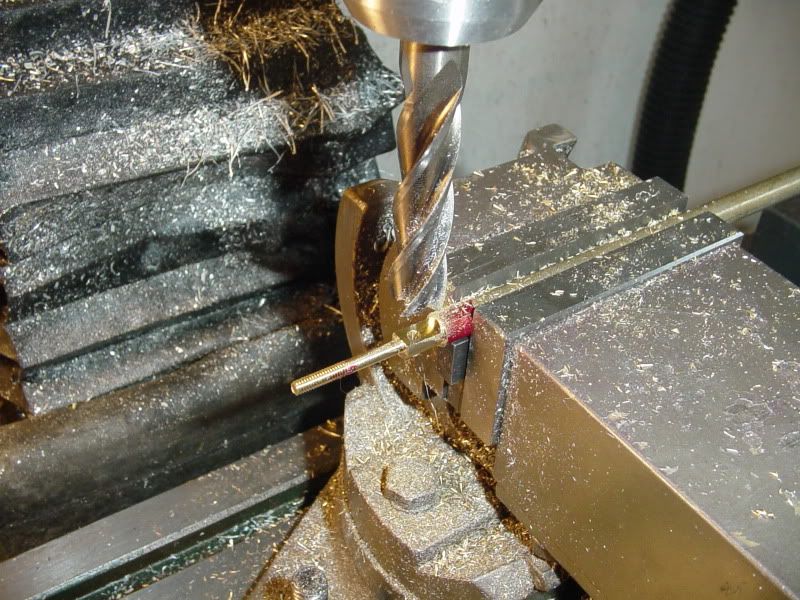
Without changing my set-up, I milled the flat on one side of the rod---
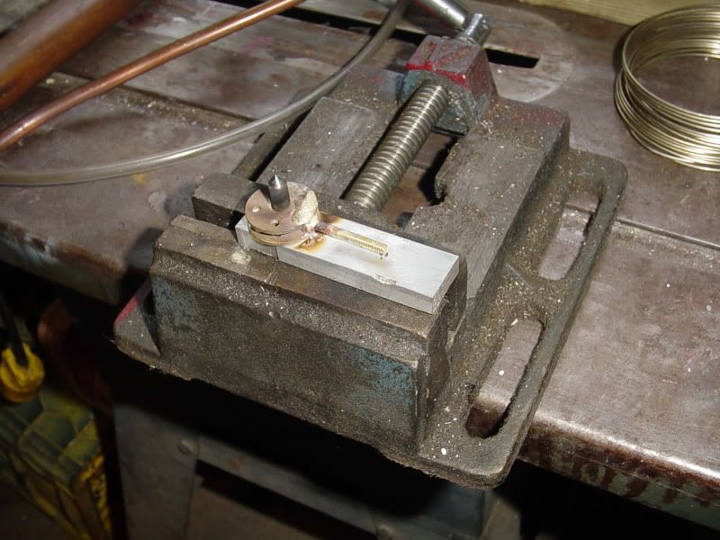
Flipped the rod around 180 degrees and stuck a peice of 1/8" diameter rod in the reamed hole and used my level to make sure that it was setting at the correct angle of rotation---
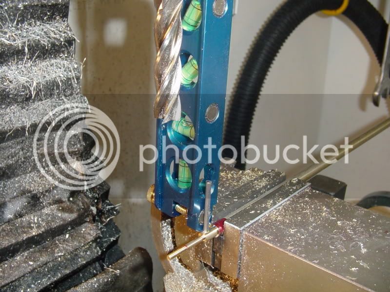
Then milled the flat on the second side of the rod.---I'm not sure if this is the correct way to do this, but it is the best I could figure out without having to buy more tooling.
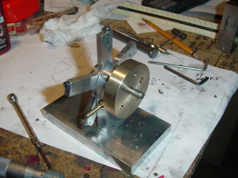
And, as I said in an earlier post, the master rod gets pinned, then silver soldered to the hub.---Yes, I'm a messy silver solderer---but once its filed, sanded, and polished, nobody will ever know. ---I did use a 3/16" drill and put a chamfer in the outside of the brass hub so that when I remove all the excess silver solder there will still be a ring of it left all around the 1/8" diameter pin. This silver soldering will be on the side of the hub that doesn't show when things are assembled.
zeeprogrammer
Well-Known Member
- Joined
- Mar 14, 2009
- Messages
- 3,362
- Reaction score
- 13
This is getting more interesting. I was reviewing the thread and some of the videos and pictures got me thinking.
When I first started this wonderful hobby last February...I got a casting kit for a Model #2A (wobbler). Messed that one up and got a 2nd. Then a 3rd and then a 4th. Finally got the thing built and running. My first engine!!!
Anyway...I now have the 'parts' for 3 additional wobblers...and hopefully some improved machining skills. So I'm thinking...why not build a radial out of them?
So like I said...this is getting more interesting and I'm learning a lot on this thread.
Looking good, Brian!
That's the way I would have milled the connecting rod. One day I'll invest in some collets and collet block...
Like most others here, I enjoy following your progress. At least one of us is achieving something in the workshop
Gordon
That's the way I would have milled the connecting rod. One day I'll invest in some collets and collet block...
Like most others here, I enjoy following your progress. At least one of us is achieving something in the workshop
Gordon
K
Kermit
Guest
When it comes to soldering of any kind... just remember this.
The Bigger The Blob, the Gooder the Job.
:big:
I heard that so long ago I can't remember who said it, but it still gets me smiling to this day.
Kermit
The Bigger The Blob, the Gooder the Job.
:big:
I heard that so long ago I can't remember who said it, but it still gets me smiling to this day.
Kermit
Similar threads
- Replies
- 11
- Views
- 925
- Replies
- 413
- Views
- 65K
- Replies
- 510
- Views
- 74K