Brians Radial Engine

Home Model Engine Machinist Forum

Help Support Home Model Engine Machinist Forum:

This site may earn a commission from merchant affiliate links, including eBay, Amazon, and others.
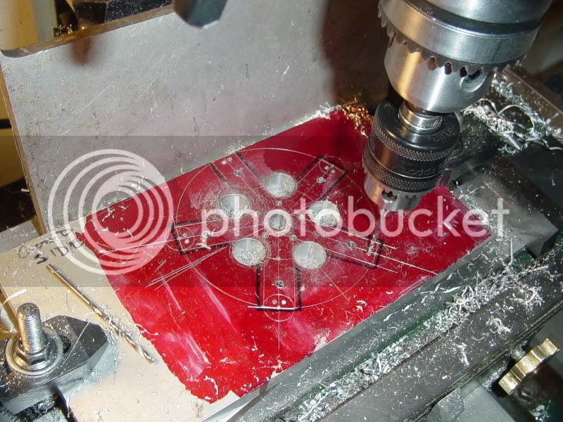
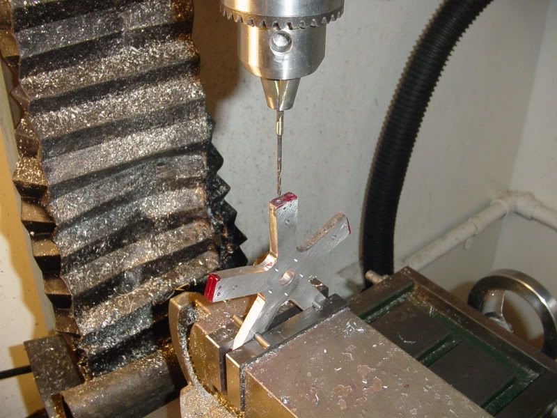
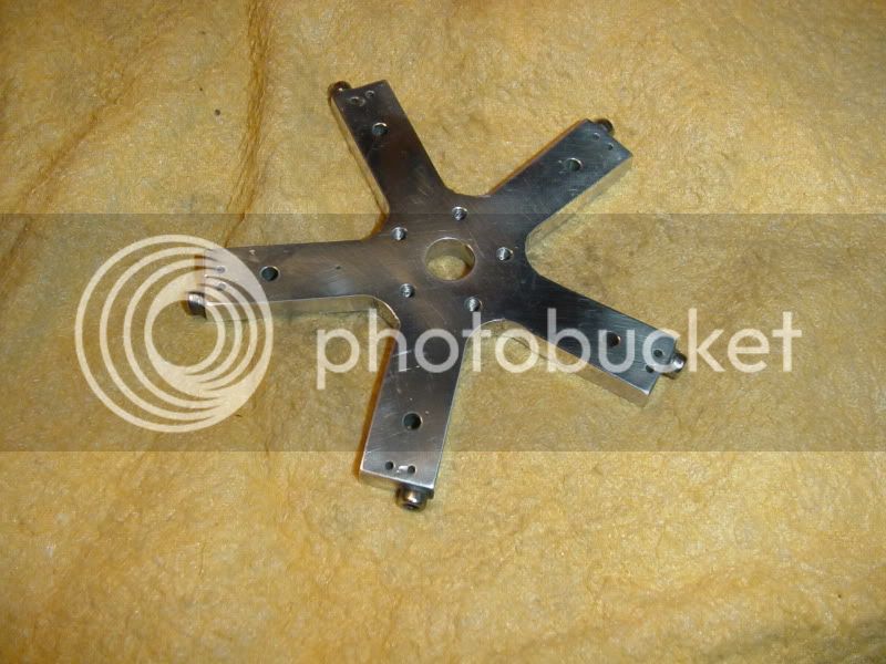
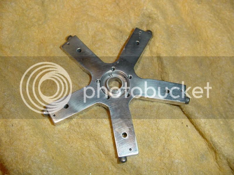
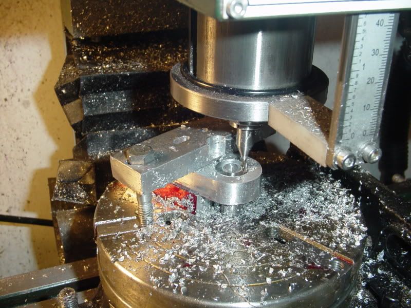
I took a look through my aluminum scrap stockpile and of course, as luck will have it, I didn't have any 1/4" plate.--So---I used a peice of 3/8" material. (I will flycut it down to 1/4" thick.) I have layed out the overall outlines with a scriber and compass and protractor. The black marker is only there to make things show up in the photograph. You will also see that I have marked one side of the plate as "good side" in marker---thats to make sure all my measurements are taken fron the same side of the plate. My little milling vice will only open to about 2 7/8" wide, so I will use a peice of "sacrificial" aluminum plate and clamp this plate directly over it to my mill table to drill all the holes in it. While I have it clamped down I will also drill the five 9/16" diameter holes in the crotch of all 5 spokes to form the 0.281" radii between them. I will flip the plate over and flycut the far side to prevent milling away all my layout lines. After all the holes are drilled, I will use the bandsaw to cut the material away from between the spokes, then stand the plate up in my mill vice to drill the 1/16" holes thru from the ends of the spokes to the center air annulus.
MAINFRAMELAYOUT001.jpg
 
Not trying to answer for Brian. (I'm not that smart) But in looking at his design it has a major difference. Its ports are timed by the motion of the cylinder not specifically relative to the crank. In a real radial engine it would be more critical since the valves have to be in time with the crank and cam. Running a little ahead or a little behind the crank may not really matter to an oscillating engine.

I am willing to be wrong here and won't take a bullet fighting for my opinion, but that is how it looks to me.
 
But without a master rod they will all advance and I don't see it working (just my thought) I could be wrong have been a time or two in the past :big:
Now if the cylinders were stationary and slide valve were used it I feel would work just fine say a rotary slide valve in the on the back side.
 
Should not take much to make one of the pistons the master rod. May make the timing a little different since the plate will be rotating a little bit back and forth with the master rod rather than maintaining a fixed orientation.
 
You fellows can't tell from the drawing, but the con rod on the top vertical cylinder is the master rod. It will be silver soldered to the rotary hub. All of the other rods pivot at the rotating hub.---Brian
 
First stage of drilling completed. It doesn't look like much, but there are 25 drilled holes in that puppy!!! There is a peice of "sacrificial" aluminum plate underneath the plate being drilled, so that I don't drill into my mill table. ---And don't get alarmed if some of the holes aren't perfectly on my layout lines. Remember, those lines were scribed by hand using an old drafting protractor, and were a visual reference only.--All the holes were drilled using ordinate measurements taken from the center hole, using the dials on the x and y feed of the mill.
DRILLINGMAINFRAME001.jpg

 
Looking good, Brian. How did you calculate the ordinate positions of the holes while doing the drawings?

Chuck
 
cfellows said:
Looking good, Brian. How did you calculate the ordinate positions of the holes while doing the drawings?

Chuck
Chuck--You missed a post.--Look back on page #2--the drawing is there.
 
I had a slight change of plan--I decided that since I was planning to use the lathe anyways to put the annular air passage in the back side of the main frame, I might as well use the lathe to cut my plate down from 3/8" thick to 1/4" thick. I drew another circle with my old drafting compass about 1/2" greater in diameter than my greatest part dimension and rough cut it out on my bandsaw. I have a hub/fixture left over from another job that has a very convenient 0.375" stub on the face and is tapped fro 5/16" bolts and also has some 5/16" clearance holes though it. I mounted the 3/8" reamed hole in the center of my plate on the stub and bolted it to the face of the hub, then set it up in my lathe and turned the outer diameter to be concentric with the hole in the center. (You will see in the next post that I had to slot one of my 9/16" clearance holes to pick up the hub bolt pattern, but thats okay---I took the material out of one of the webs that will be cut away between the spoles.) Here is a picture of the step just described, and of the hub/fixture.
MAINFAMEMACHINING001.jpg

MAINFAMEMACHINING003.jpg
 
I then reversed the jaws in my 3 jaw chuck, mounted the plate as shown, and then turned the plate to 1/4" thick in the area I needed it to be 1/4" thick. I also ground an old cut off tool to a vicious looking point and plunge cut the annular groove.
MAINFAMEMACHINING002.jpg
 
Here we are drilling the air galleries that reach from the end of the arms to the center annulus. This was a bit trickier than I anticipated. My mill soesn't have enough headroom to hold my precision chuck and the main chuck and a 1/16" diameter drill.--And besides, my 1/16" drills weren't long enough!! I hunted around and found an 0.075" drill, and used it to drill into the end of a 1/8" diameter rod in the lathe, silver soldered it in place in the end of the rod, then chucked it up in my main chuck (which won't hold anything smaller than a 0.105" dia drill because it won't close enough to grip it). Also, you can see how I inserted some 1/8" diameter rods thru the reamed holes in the part being drilled to level it in the milling vice.
mainbdyfinished002.jpg
 
And Voila'---we have a pretty shiny starfish. This part is complete now. I have showed the front side and the rear so that you can see the annulus that distributes air out the 5 spokes.
mainbdyfinished003.jpg

mainbdyfinished004.jpg

 
Brian you solved well the setup problem with this piece and the result is very nice
go on with the build, and thanks for sharing

 
I think I will build the stand next. I originally had it made from an angle, but realized I couldn't machine the annulus on the lathe if did that.
VERTICALSTANDFORRADIALENGINE.jpg
 
Brian, Great job.

If you meant your last plan post to be a .pdf file, it didn't make it.

Ron
 
ozzie46 said:
Brian, Great job.

If you meant your last plan post to be a .pdf file, it didn't make it.

Ron
Ron--I didn't plan it to be a .pdf---Mainly because the drawings as well are a 'Work in progress". I don't want folks downloading and saving drawings untill I have made revisions as necessary as the work progresses. I will post all the drawings for this as downloadable .pdf files once the engine is running and all drawings have been corrected.---Brian
 
This is not a "milestone" post.---Rather I have posted it because I'm so damn proud!!! I FINALLY GOT TO USE MY ROTARY TABLE. I had planned to cut the air annulus in this part on my lathe, but decided at the last minute to use my rotab. I paid a lot of money for it when I bought it 2 years ago, and I have only ever used it once before, to cut spokes in a flywheel for my twin cyl. horizontal engine. It works very well for the operation I just performed, and I feel so good about it I had to take a picture. You will also see that as I got part way thru the operation, I had to stop and cut a clearance in the hold down strap to allow me to cut to the depth I needed.
ROTABWORK002.jpg
 

Latest posts

Back
Top