Brian Builds the Kerzel Hit and Miss I.C.

Home Model Engine Machinist Forum

Help Support Home Model Engine Machinist Forum:

This site may earn a commission from merchant affiliate links, including eBay, Amazon, and others.
;D 'round this way we say 'tight as a fish's a**e'

Thinking over your woes tho tho Brian, I have got to wondering whether your changing the points set up to the 'other' side, where it is working on a 360° cycle, rather than a 720° has something to do with your problem.
 
Brian

This may sound like a dumb question but since you have no compression there is a slight possibility that it might not be a dumb question.

How much clearance do you have in the valve train? If there is no clearance between the valve/lifter/cam lobe, then the valve may not have room to close which would mean no compression. The more you try to lap the valve seat the worse the problem would become if you didn't adjust the valve lash.

When all else fails sometimes you just have to ask all the questions not just the obvious ones. Hope that you get it running soon. :bow: :bow:

Cheers :)

Don

 
I know lots of builders use valve cages but I don't. I'm concerned cages can leak if not properly fit. I think there's not a lot of metal between the combustion chamber and the exhaust and intake passage to seal the cage. It wouldn't be unheard of to have a leak there.
 
Thanks guys---I do have clearance between the rocker arm and the valve stem, and I'm not the least bit concerned about valve cages. The points work fine the way I have them as witnessed by how well the webster runs. This is purely and simply a fitment issue of valves to valve seats. I will probably build new cages and re-use my current valves, but they are not going back into the engine untill I have performed some kind of "Out of engine test" for an airtight seal.
 
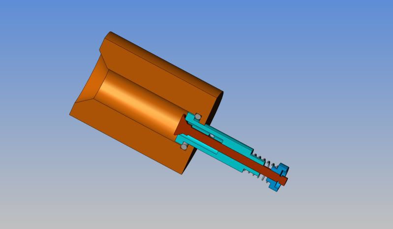
I am toying with the idea of something like this "cut away" view, which shows the valve and valve cage assembly complete with spring and keeper, inserted into a brass fixture with an o-ring seal in the bottom of it. The valve cage would have a 1/16" hole drilled thru the side, where the main port hole will eventually get drilled. If I could then intoduce pressurized air into the open end of the brass fixture, I could hold the end with the 1/16" valve port submerged in a glass of water to do a "bubble check" to see if the valve was sealing or not. If one could ensure that the seal was 100% or close to it, then the cage could be loctited into the cylinder head with heat resistant Loctite. i wouldn't press fit the cage---the walls are very thin brass, and won't take much "pressing" without deforming.
ASSY-VALVECAGETESTER-3.jpg
 
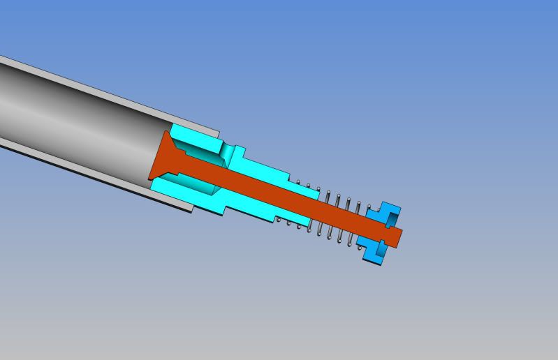
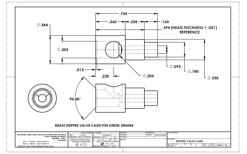
I've got it!!! A Eureka moment!! I am going to make new brass valve cages and try to get away with re-using my current valves. I am going to make "stepped" valve cages with two outside diameters (well 3 actually if you count the small register that sticks up above the top of the cylinder to center the compression spring). I will drill a 1/16" dia hole thru the side of the cage, (which will be "dissapeared" when I drill the full sized port hole after final assembly. I can slide a peice of rubber tubing over the valve and put 20 or 30 pounds of air pressure on it, and submerge it in a glass of water to check for bubbles escaping out the 1/16" hole. Once I achieve an air tight seal, the cage will be loctited into a stepped hole prepared for it in the existing cylinder head. The face of the cage sets flush with the inside surface of the cylinder head and the "step" keeps it from blowing out under compression. The existing hole through the cyl head is 0.25" the stepped hole diameter will be 11/32" dia. the valve head is 0.25" o.d. and the hole inside the cage is 0.203" dia.
ASSY-VALVECAGETESTER-CUTAWAY.jpg
 
Sounds to me like overkill. Like I posted earlier, building new parts without ever testing the old ones is a tough road to go.
Speaking of overkill, for one thing all the pressure you need can be blown with your mouth. find a way to seal an 1/8 inch brass tube in the sparkplug hole. Add to it a couple of feet of model airplane engine gas line or similiar tubing and blow on the tube while the engine is dunked in water. Look for bubbles. The leak might be a valve, valve cage, head gasket, or just maybe rings if there are any. For valves my rule of thumb is 1 bubble every 4 or 5 seconds is maximum leakage.

 
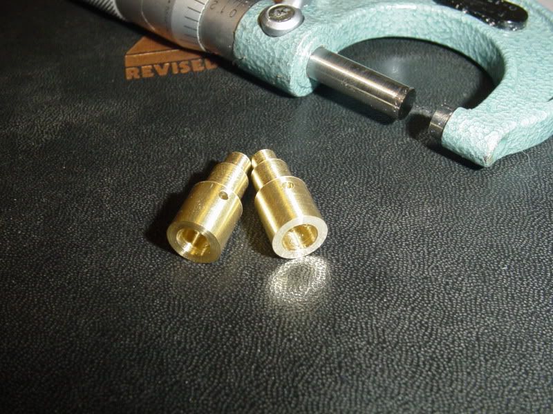
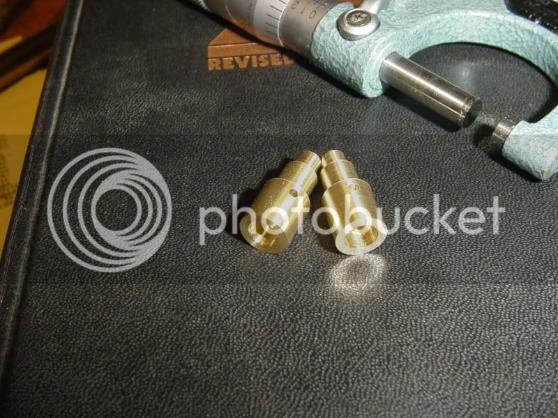
I managed to steal an hour this evening and make my "stepped" valve cages. I used my new handy dandy home made valve seat cutting tool to put a VERY small 45 degree chamfer where the valve seats. I would estimate it to be .010 to .015 deep, but I have no real way of measuring it---I just know its very small. and yes, Jpeter--I have conducted all of the tests you are advising---MANY times. They are documented somewhere in the 37 pages of build notes that precede this one.
STEPPEDVALVECAGES002.jpg

STEPPEDVALVECAGES001.jpg
 
Sorry to sound so pushy but much like you I was getting frustrated. Did you find the leak? From where were the bubbles coming?
 
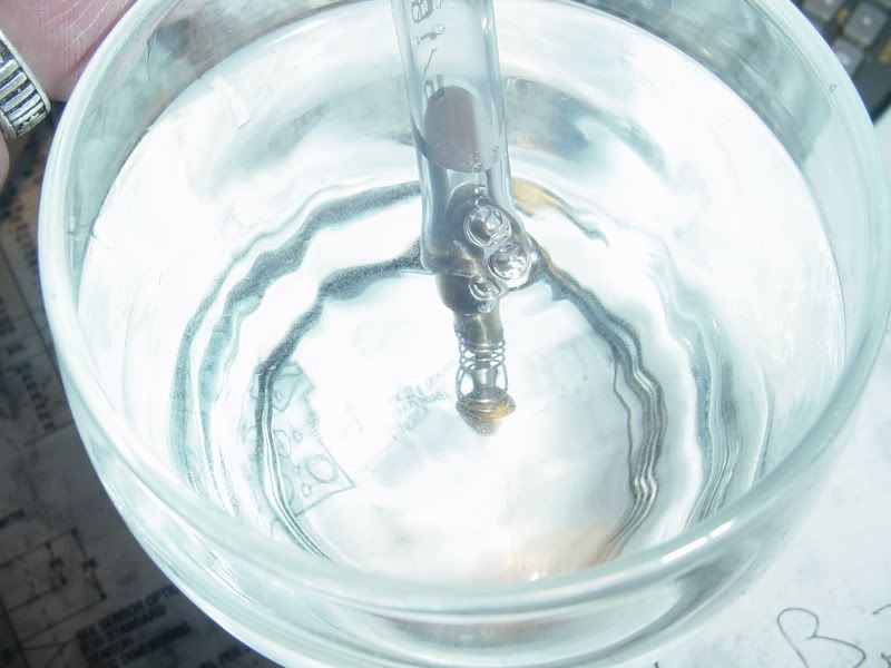
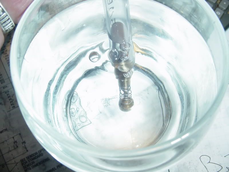
Now what???? I'm snookered!!! I built the new "stepped" valve cages as accurate as I am capable of doing. I used my "hand made valve seat cutting tool" to cut a very small 45 degree seat. I used the new valves I made from drill rod and as per Bogstandards advice I cut the valves at approximately 1 to 2 degrees less included angle so that it would have a theoretical "line contact" where the edge of the valve closest to the head contacts the seat. I lapped the valves to the seats with valve grinding compound ---and they still leak!!! They don't leak an outrageous amount, but they still aren't "air-tight". I bought some clear plastic line and built a test rig like the one I modelled in the previous post, and submerged the valve in a glass of water--thats what you see in the picture. I blew in the tube untill I was dizzy----I "twiddled" the exposed end of the valve with my finger while blowing.---they bubbled. I made an adapter up and put a regulated air compressor line on the other end of the tube, thinking that perhaps higher air pressure would push the head of the valve against the seat for a better seal.---It just bubbled more. I haven't modified the cylinder head yet to accept the stepped valve cages---I don't see any point in doing so unless I can get the valves to stop leaking BEFORE I install the new cages. I am at a complete loss as to what to do next.----Brian
Nowwhat002.jpg

Nowwhat001.jpg
 
I used the permatex stuff. Don't know where to get anything else. All the automotive stores around here only seem to carry the Permatex 474G and nothing else.
 
brian if you can not find any extra fine clover lapping compound to you know anyone that does mold work. maybe you can find someone that has some diamond paste , that is used for polishing. you could even use some silver polish or brasso as they are both fine.i think you lapping compound is to coarse. good luck jonesie
 
I was able to borrow a small baggie of 320 grit and of 600 grit lapping grease from my local machine shop. I am currently relapping each valve /valvecage combination with first 320, then 600, then toothpaste.
 
I thought you were taking some time off with this one?
 
I'm very pleased to announce that the lapping with 320,600, and toothpaste seems to have worked miracles. Both valves seem to be absolutely airtight (by lungpower at least) when performing the same bubble test that I did earlier today. My god, what a difference in the "grit" feeling between even the 320 lapping compound and the Permatex junk. The Permatex feels like it has granite boulders in it by comparison. I have to drill and ream the relief in the cylinder head for my stepped valve cages and loctite them in now, and lets keep out fingers crossed.----Brian
 
It's all over but the shouting, then. Nice to hear you've worked it out.
 

Latest posts

Back
Top