Anybody want to guess---

Home Model Engine Machinist Forum

Help Support Home Model Engine Machinist Forum:

This site may earn a commission from merchant affiliate links, including eBay, Amazon, and others.
Brian Rupnow said:
Crankshafter---I understand your reasoning with putting the points on a seperate piece to enable "timining" the points, but first I will try it "as per plan".---I looked on the web link at all the other people around the word that have had success building and running the Webster as built "per plan" so I will try it that way first. If I find that point timing is an issue, I will add a seperate mounting disc later.

Ignition timing is accomplished by turning the points cam on the crankshaft. I timed my Henry Ford engine by rotating the crankshaft to the point where I want it to fire, then loosen the setscrew holding the points cam and rotate it in the direction the engine turns until I feel the flat contact the rubber on the points.

Chuck
 
Thanks Chuck. I had that one figured out. After 40 years of building, racing, and driving hotrods, ignition timing doesn't hold too many mysteries for me. ;D ;D---Brian
 
The following excerpt is copied directly from the Webster instuction sheet:

SHEET 8. The EXHAUST CAM started out as a .185" thk. disk of steel .712" in diameter with a reamed
.375" hole though it. It was offset turned on the lathe as described by Hamilton Upshur in Volume 79
of Strictly I.C. magazine. There are many other methods - use whatever you are comfortable with.
The plans call for hardenening of many parts, i.e. CAMSHAFT, CAM, ROCKER ARM, etc... This not
necessary, but doing so should result in a longer wearing engine.

Can anybody shed some light on this "offset turning" that the author is talking about?
 
Brian,

I think what he's talking about is this. You need to be able to fix the cam blank onto a shaft so the blank won't turn on the shaft. Let's say you use a set screw. Then you chuck the shaft into the lathe using a 4 jaw chuck so the shaft is offset from center by a designated amount. The further off center you chuck the shaft, the faster the rise time you'll have on the finished cam. As a starting point, I would say 5/8" - 3/4" off center.

Now, assuming your cam is to have a 1/8" lift, you bring the lathe bit up and make several passes to cut away a 1/8" arc from the outer edge of the spinning cam. Then, you stop the lathe, loosen the set screw, and turn the blank maybe 3 - 5 degrees. Do not loosen the chuck holding the shaft. Retighten the set screw and make another pass with your tool bit at the same setting where you left it from the first pass.

Keep doing this until you go far enough around the blank the you form a near point where the end cut meets the first cut. That becomes the lobe of your cam.

You can also use this same process using a rotary table and a boring head on a mill. To see how I did this, look at response #52,little over half way down the page, in this post:
http://www.homemodelenginemachinist.com/index.php?topic=6352.135

Hope this helps...
Chuck
 
Thanks Chuck---It looks a bit too involved for my current capabilities. I remember looking at it when you posted it originally, and being very impressed. Are/were you a machinist by trade, or are you a self taught hobbyist?
 
Brian, I'm self taught, never had any training or mentoring. But I do read a lot!

There's actually nothing very complicated about the offset turning. None of the dimensions are really very critical.

Chuck
 
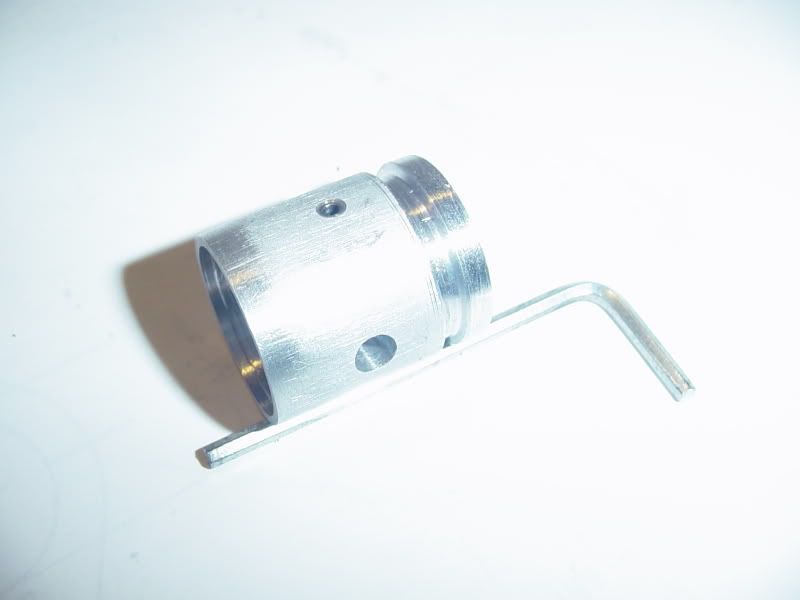
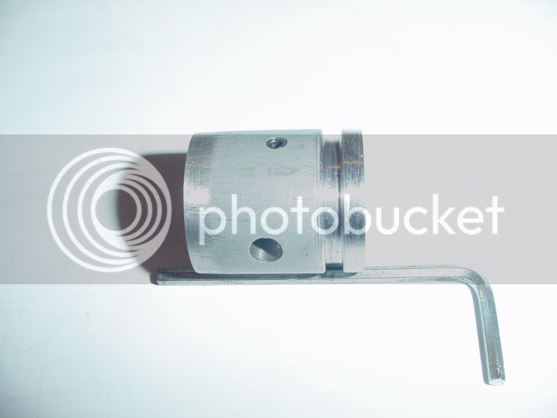
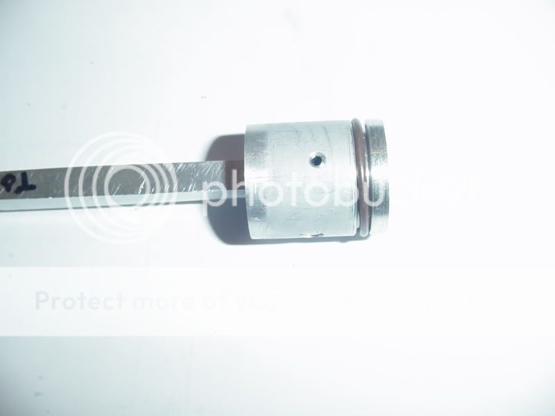
We have a ring groove!!! Despite my greatest care and attention, the groove ended up being .059 deep instead of the .053 to .055 that the spec sheet called for, and 0.90 wide, instead of the .095 in the spec sheet. However, Its not going back into the lathe now. I did break the top sharp corners of the groove with a file while the work was still in the lathe.
pistonringgroove001.jpg

pistonringgroove002.jpg
 
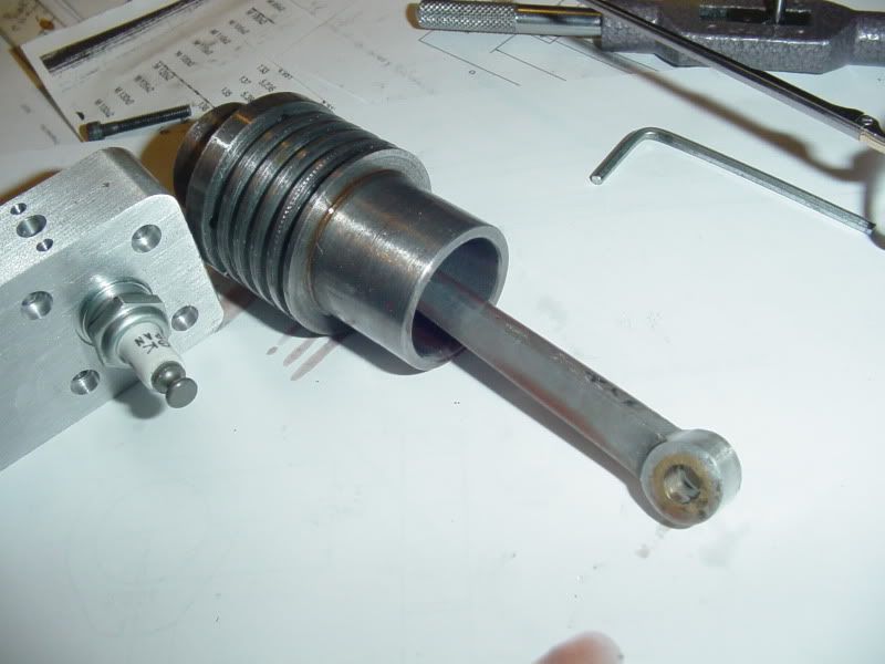
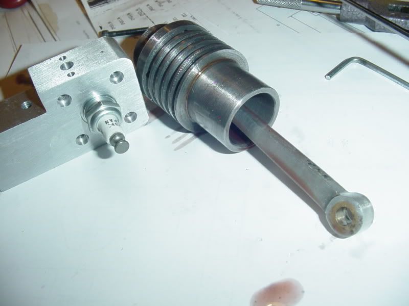
Here we have the Viton o-ring in place.--It went on with very little kicking and squirming----The leading edge of my piston had a fairly sharp edge that I didn't want to remove, so I put the ring into place from the rod end. You can see in the picture that a .090" wide gap gives some room for the o-ring to flatten down into when it is compressed into the bore of the cylinder
(I hope)!!!
pistonwithring-installed002.jpg
 
And here we have the piston (with o-ring) inserted into the cylinder. When I made the cylinder I machined a fairly decent "lead-in" angle on the end which is opposite the spark plug end, because I anticipated a fight getting the piston with a ring in place into the cylinder. (Remember here---I've been building hotrod engines all my life, and I have fought this "piston with rings into cylinder" war before.) I coated everything---piston, and cylinder with some real nasty, slimy chain oil (for my chainsaw), said a short prayer to the engine gods, and gave a push and a wiggle---and in it went. Mind you, its stiff.---Its damn stiff--but its in there, and it moves from end to end of the cylinder. I foresee a good run-in being required to loosen things up a bit before I ever go to run this engine, but thats what the good Lord made variable speed drills for !! :D :D :D---Also, you will see that I got the cylinder head tapped and the worlds smallest spark plug installed. (I tried the tap and tap drill out on a piece of scrap aluminum before using it on my cylinder head, and tried the sparkplug for fit in the scrap piece. I just HATE having to remake parts because I was a donkey and didn't check things first.
pistonwithring-installed003.jpg

pistonwithring-installed004.jpg
 
Coming together real nice, Brian. Shoot, you'll have it running by the end of the week! ;)

By the way, is that chain saw oil good for general lubrication? I'm always looking for oil that will stick and not have to be refreshed all the time.

Chuck
 
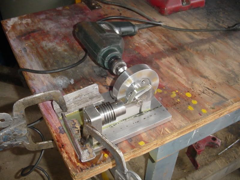
And here we have it---happening Now---The RUN IN!!!! everything is liberaly coated with oil, the drill is wailing away at about 3/4 of its top speed. I will leave it for an hour, checking about every 10 minutes to add more oil to everything. (I never said it wasn't messy.) and yes Chuck, chainsaw oil is formulated especially to cling to the chain and bar of a chainsaw while the saw is cutting down trees. It is slimey, slippery, and sticks like $hit to a wool blanket!!!
firstrun-in002.jpg
 
Damn---I just got crotch oiled!!!! Hint---Do not stand in front of open intake port and squirt oil down sparkplug hole!!!!!
 
Brian.
Lookin' great. th_wav
I just back from the cave, had to flip the Webster. Oh, oh, how sweat it sound when its fires and run ;D Think I have to make a big brother of the engine. One day......
Brian now it's time for you to make the rest of the parts. Just all the tiny small, time consuming ones :big:
But you have the skills and guts, so no problem.

CS
 
I hope you get that o-ring loosened up. On my engine the o-ring started out tight and never did get better. I finally had to cut the groove deeper. Now the o-ring slides up and down lik'a butta! And the compression is very good, too.

Charlie
 
Oh Oh---I have my W.M. Berg catalogue out here, and I notice that the 24 tooth gear specified by the man who made the plans has a 0.25" bore, yet it has to fit on a 5/16" dia. crankshaft. I don't see it mentioned in the plans that the bore has to be opened up to 5/16", but it will have to be to fit. Did anyone else notice that?
 
I'm rooting for you Brian, this is quite interesting and to see/hear about the trials and tribulations you encounter has made the journey that much more pleasing. Now it's not that I enjoy seeing anyone fail, it is just that by paying attention to what others have done, I learn little tricks of how to do certain things and what doesn't end well. You'll be firing this one off before the weekend-ish or close thereafter.


BC1
Jim
 
Brian Rupnow said:
Damn---I just got crotch oiled!!!! Hint---Do not stand in front of open intake port and squirt oil down sparkplug hole!!!!!

:big:

I did a similar thing on my watch makers lathe a while back.
Stripped it down, oiled all the bearings, put it back together and stood in front of it when I started it up.
That white T shirt went from being a 'good shirt' to a 'workshop shirt' :big:
 
Brian Rupnow said:
Oh Oh---I have my W.M. Berg catalogue out here, and I notice that the 24 tooth gear specified by the man who made the plans has a 0.25" bore, yet it has to fit on a 5/16" dia. crankshaft. I don't see it mentioned in the plans that the bore has to be opened up to 5/16", but it will have to be to fit. Did anyone else notice that?
Of course Brian! It was not an issue, didn't even drill the hub but used the more uncommon "radical press fit" with a lot of grunt behind the effort to get it on the axle. :D I'm learning alot making these motors! ;) Dave.
 
Dave---Aint no way in Hell you pressed a hub with a 1/4" bore onto a 5/16" axle!!! RadfordC--You may very well be right. Even after running for an hour, the piston is very tight moving in the bore of the cylinder.
 
Back
Top