A new attempt at making piston rings

Home Model Engine Machinist Forum

Help Support Home Model Engine Machinist Forum:

This site may earn a commission from merchant affiliate links, including eBay, Amazon, and others.
Unless you start with a sleeve larger than your bore you will most diffidently end up with out of round condition when you reduce the dia then put them back into the 1.000 bore on your engine. I would venture to say they are closer to round than they will be after doing what you are proposing. make your starting sleave a few thosands bigger that your engine bore and then finish to your bore size.
 
I still say your cylinder bore is egg shapped from all the honing you have done on it. You can check quick by putting it in a 4jaw and trying to dial it in and see if it will run true. Just because it will run with o ring does not mead it is round as o rinds are very forgiving of and out of round cylinder.
 
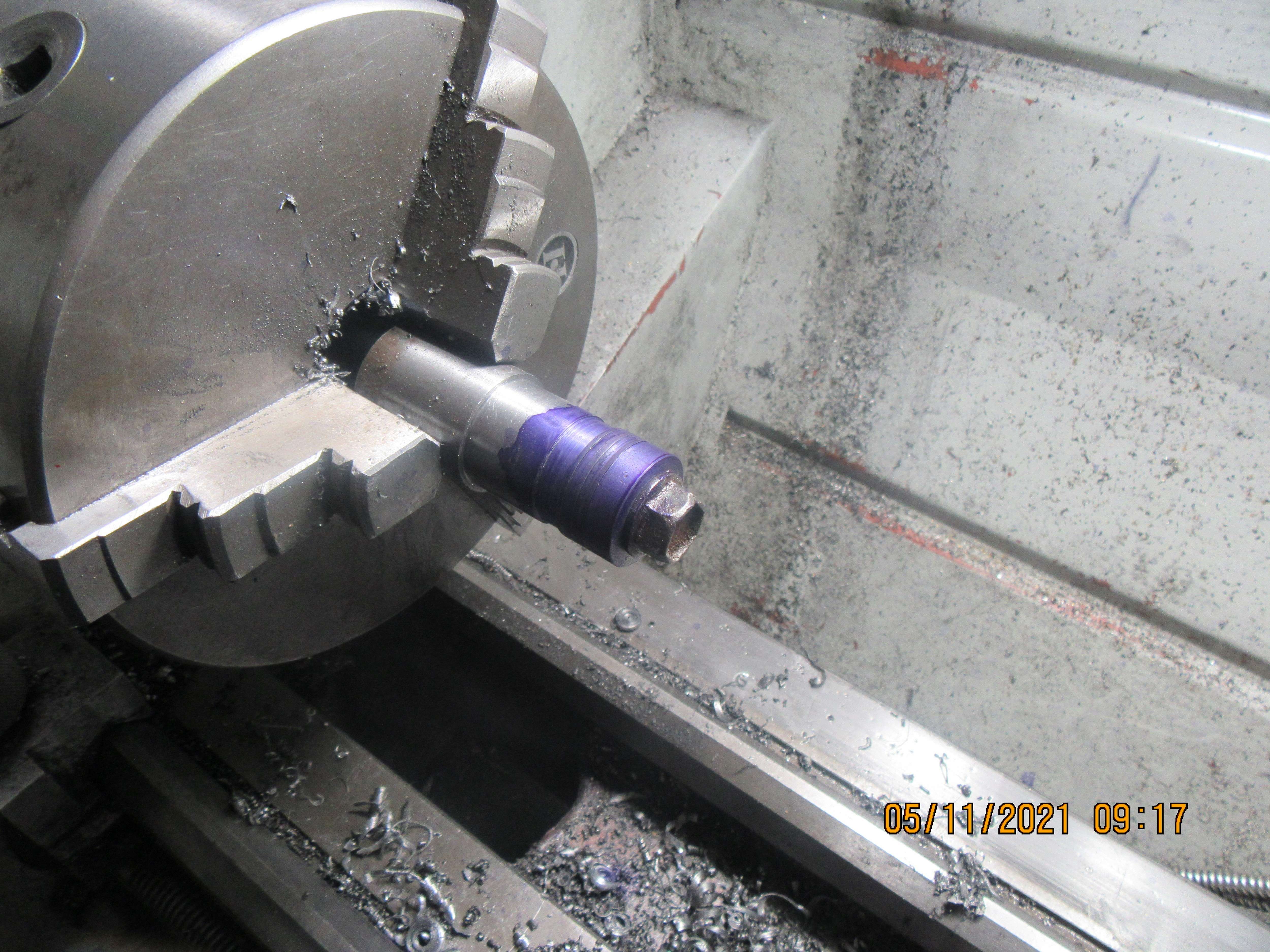
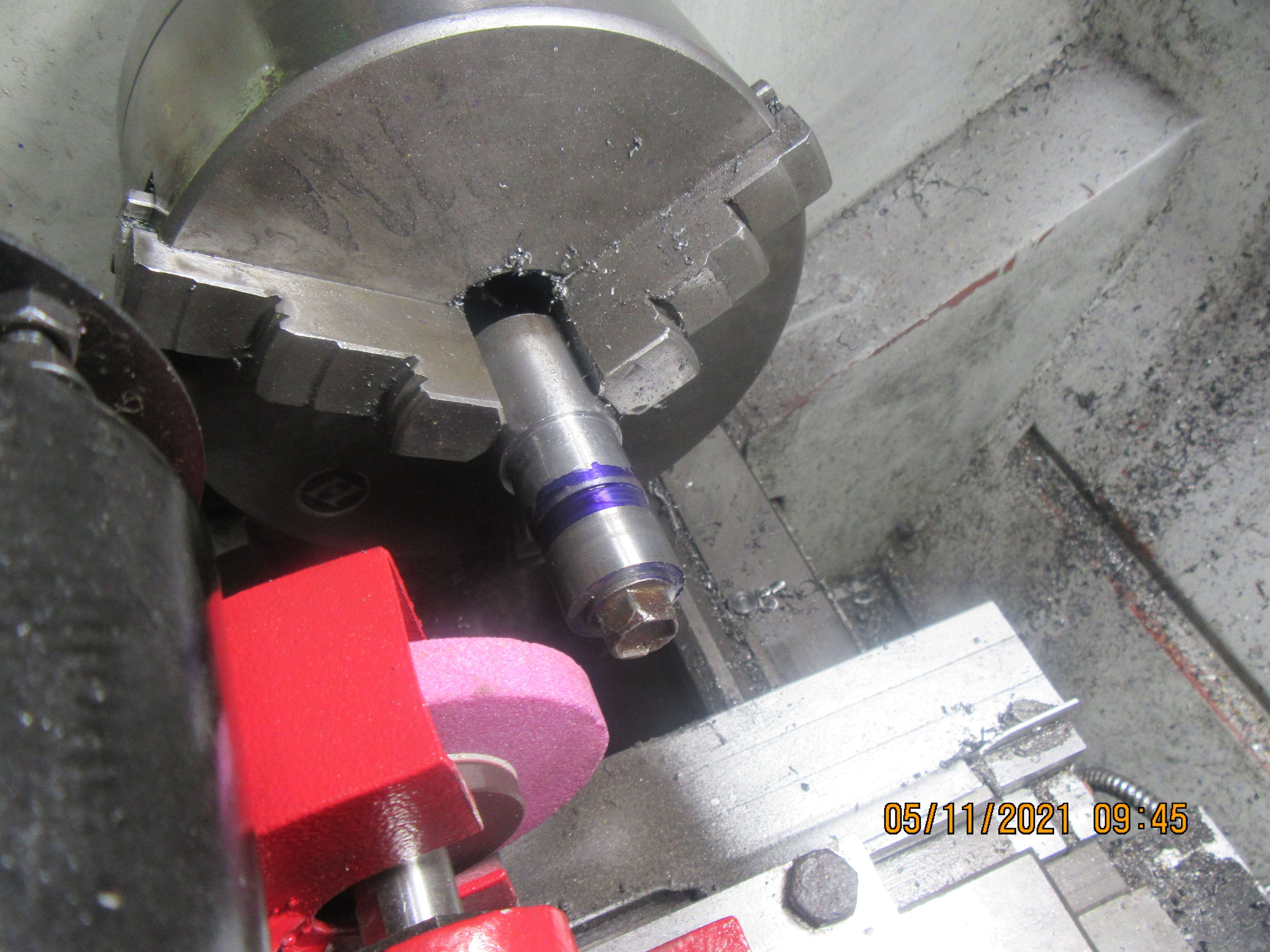
I'm not absolutely sure of what I'm doing here, but that has never stopped me before. I wanted to have a good "visual" on the rings to know when I had reached a point of perfect roundness, so I coated everything with blue layout dye before I went to bed last night. This morning I mounted my toolpost grinder and taking .002" depth of cut, I made repeated passes over the rings until all the blue was gone. At this point, knowing my rings are perfectly round, I will dismount them from the grinding jig and try them into a cylinder.
7g8yhd.jpg

kVbYN7.jpg
 
I didn't "true the wheel" with a diamond dresser. I did buy a diamond dresser to true the wheel, but didn't use it this time. (I still have to cobble something up to hold the diamond dresser while I do that, just haven't got that far yet.) Keep in mind, I haven't done this before, and mostly I wanted to try it out for "process". The rings were extra rings that I had made, but they weren't that great. I don't expect to actually use these rings, but I had to try the new fixture and grinder out for "process". There are a couple of things I will change, but they mostly relate to the tooling. I find that when using my 3 jaw lathe chuck that if I take anything out of the chuck, it is almost impossible to put it back in the chuck and not have the outboard end wobbling. I am going to investigate using a tailstock support for the free end to make it run true, but I have to investigate and see if I have room to do that. I will clean up the lathe when I get this sorted out.
 
How about using one of the “soft blank” morse taper arbours to fit your headstock, you can machine it as the fixture, and know it will always run true again after removing and replacing. Added benefit, no dismantling of 3 jaw chuck to clean out grinding dust. Or if you have a suitable collet, hold the fixture in that.
 
Has anyone tried making a heat treating fixture along the lines of an expanding mandrel/ reamer, using a taper to expand the ring inside a sleeve, heating, then “expanding” fully to force the heated ring into close contact with the bore of the sleeve, then complete the heat treatment? Would this give a more uniform pressure against the cylinder wall by keeping the ring truly circular during treatment?
 
Mark your fixture as to where each jaw contacts the fixture. Jaw #1, Jaw #2, Jaw # 3. Also mark the overhang from the chuck. Machine the fixture and mark it before you remove it and then when you put it back in the lathe have it in the same position.
 
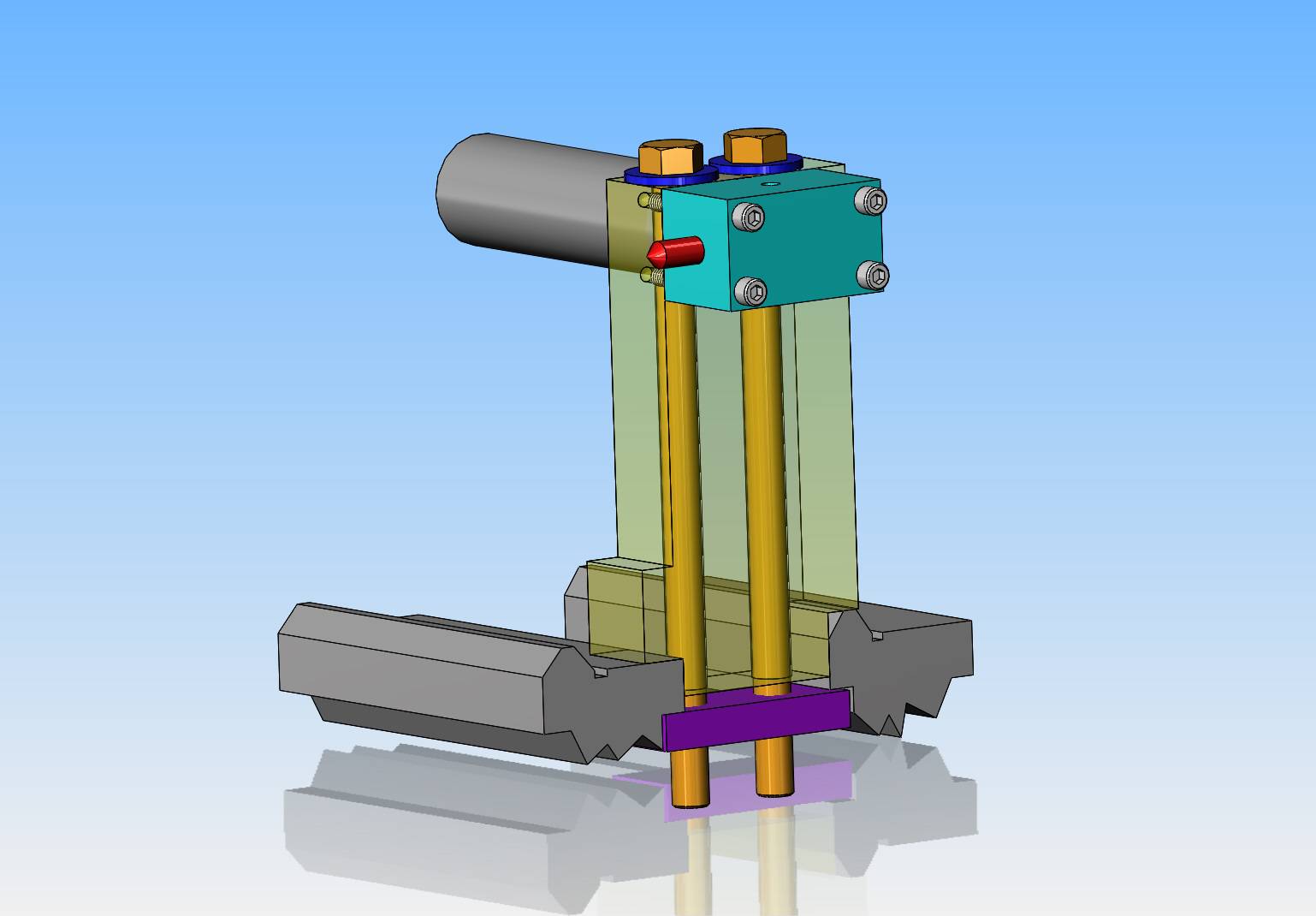
A part of this goose-chase is going to be building an independent support for the diamond wheel dresser. I will have to build this as an independent stand alone item, because I have nothin else that will work to hold it.
utRLsv.jpg
 
You make a simple holder for tailstock. Just use morse tapper holder with holder for wheel dresser.
Keep the dresser very short in holder I just keep the stick out front ¼" to ½" .
I made mind out 1" bar stock and #2 morse taper

Dave

A part of this goose-chase is going to be building an independent support for the diamond wheel dresser. I will have to build this as an independent stand alone item, because I have nothin else that will work to hold it.
utRLsv.jpg
 
Last edited:
Hi All. A lot of chat about "the weather" here, but Brian's post of using Mr. Chadwick's fixture in post #117 is correct. Exactly the same process as used in piston ring factories. I.E. machine the rings close to "EXPANDED" size - leaving 0.002" or 0.003" for finish grinding. Cut the split. Fit in a "sized" bore on the fixture, then tighten to clamp and hold the ring at that diameter. (Sorry Doc, not an oversized bore!). BUT you need the sizing diameter to be concentric on the clamping fixture. Otherwise, you'll make rings that are clamped eccentrically - so will need grinding under-size to get them round. IF the cylinder is a precise sliding fit on a shaft at "finished" diameter, and slides forward over the rings to be clamped, then concentricity can be assured before grinding. Brian will understand, I am sure, without a drawing.
At Hepworth and Grandage (Piston ring factory) in Sunderland in 1990 they had packs of dozens of rings going onto the mandrels and being clamped for grinding. The long cylinder would locate on a long shaft on the inboard end - at true concentric size in the grinder - to ensure the rings were concentric. There was just enough relief at the end of this shaft for the grind-stone to finish the cut.
Anyone need a drawing? I have a pencil I can sharpen...
Enjoy!
K2
 
Oh, My Father made a fixture - basically the same as Mr. Chadwicks - and used his model cylinders as the gauge for setting the rings for size. He didn't have a grinder on his 1930 3" lathe, but just took the finest cut with a freshly sharpened and dressed tool. He had compression straight off.
Brian, Winding the engine by electric motor probably won't bed-in rings against the bore, as the rings in service rely upon gas pressure for most of their tangential force to push them against the bore. Wound by motor, they are more likely just to "float" over the lubricant - sorry, lapping paste? - rather than apply enough pressure to "cut metal". Hepworth's just did a short lapping with lapping paste in dummy cylinders, which rotated maybe 20degrees between each stroke, and on a crank arrangement so the rings effectively saw the few degrees oscillation of their true axis in relation to the axis of the bore, as they will in a finished engine. This "barrelling" effectively "took the corners off" and was only measurable at very high magnification. But it meant that the rings assembled to an engine didn't really need running-in, as they were already run-in to a circle of bore size. Without the factory machine, we have to run-in models - typically at half-load and half max. speed for an hour or more. (Maybe we don't all manage that?). It takes a long time on models and real engines that are without the lapping compound used in the factory, but with lubricating oil instead.
Therefore, there is some advantage of bought rings... but we usually "get by" with the imperfections we can't overcome in our workshops.
My plan is to make some wire rings. But only after I have made the rest of the engine? - Next winter, possibly? First I'll try O-rings though?
Hope this helps?
K2
 
Hi All. A lot of chat about "the weather" here, but Brian's post of using Mr. Chadwick's fixture in post #117 is correct. Exactly the same process as used in piston ring factories. I.E. machine the rings close to "EXPANDED" size - leaving 0.002" or 0.003" for finish grinding. Cut the split. Fit in a "sized" bore on the fixture, then tighten to clamp and hold the ring at that diameter. (Sorry Doc, not an oversized bore!). BUT you need the sizing diameter to be concentric on the

But how do you grind to the correct dia when they are clamped at the dia of the cylinder. If you take a ring insert it into a sleeve the same dia as the cylinder and clamp it you have no material to grind unless you grind it under sized. That was the point I was saying. The sleeve you use has to be slightly larger than the finish size you want.
 
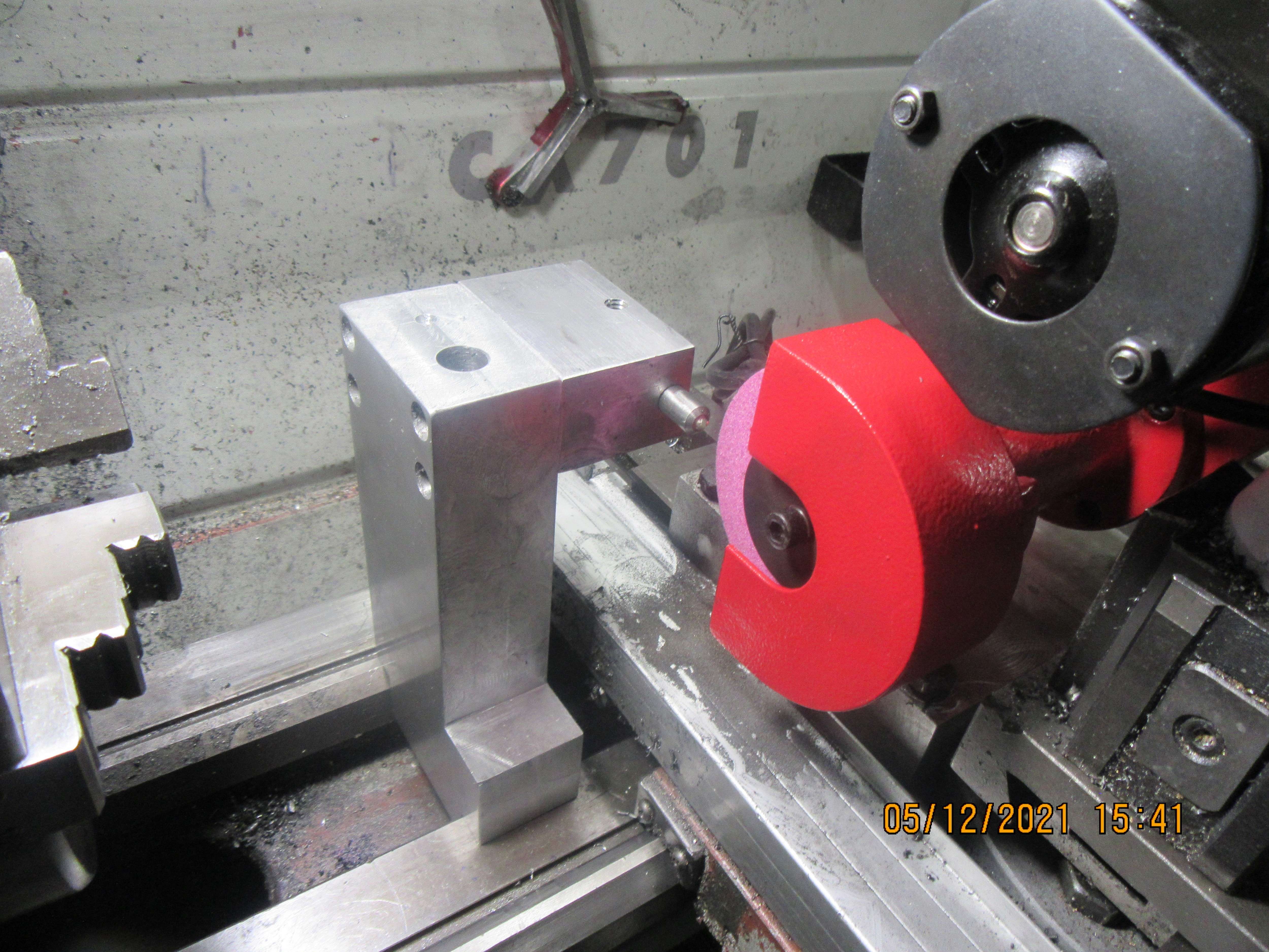
And there it is---My version of "Diamonds are forever". This stand holds the diamond for truing the grinders abrasive wheel. it doesn't look like much, but there's a days work in that thing. My bandsaw really, really doesn't like cutting 1 1/2" thick plate. It's so slow that I feel like I'm going to start growing moss while I wait for it to finish a cut. I still have to make the plate that goes across under the lathe ways and the piece of 1/2" all thread rod that comes up thru the vertical plate and gets a nut on it to hold everything stable. Those of you who are sharp of eye will see that the design changed a little bit from the model I posted yesterday.--Two 1/2" threaded rods are overkill.
mbjH79.jpg
 
Ok. I agree.
In the H & G factory I saw the cylinders, but can't remember the details of sizes. I now remember they set the ring gap correctly. Does that help?

K2
And the od would have to be set over sized to allow for grinding.
 
Back
Top