A new attempt at making piston rings

Home Model Engine Machinist Forum

Help Support Home Model Engine Machinist Forum:

This site may earn a commission from merchant affiliate links, including eBay, Amazon, and others.
So check your cylinder is round?
Because if the cylinder is not round you will not know where you are wrong

That would be my guess as a lot of honing by hand to get cylinder really smooth as for _o_ ring set up may have egg shapped cylinder same thing goes for emery paper on the lathe to much emery paper and you will have a shaft that is not truly round.
 
Brian, please dont hate me for adding my method for making rings - which i have only made them for 1 engine.
1. measure the dia of the ring groove on the piston. bore the cast iron to slightly larger so the ring can compress past the major dia of the piston.
2. turn down the cast iron until it just fits into the cylinder. not a sloppy fit. i used 500 grit emory cloth to hit the fit when it was getting close
3. part the rings, check to see if the rings edge will fit nicely in the ring groove of the piston. if not i used a surface plate and 500 grit sand paper until it was that nice slide in fit.
4. snap the ring using side cutters. at first i thought this would dent and deform the ring at the cut but it didnt. it just caused them to snap.
5. i just barley filed the gap. didnt even bother to measure it. just so there was a very little gap.
6. used a rod to spring the ring gap to the size i wanted and heated them to red over a bed of sand. some fell of the rod as other instructions said they would and some did not. but they all at least started to move on the rod as they were spread on the rod at an angle and gravity started making them hang straight down.
7. dont think this mattered whatsoever but i put them in the toaster oven at its highest setting which i believe was 450 f. i then went and worked on other things for a few hours. - i let ring cool naturaly.
8. test the fit in the ring grove just by stick the side of the ring in, not actually spreading and installing the ring. if it swelled from the heat then i hit it on the surface plate / 500 grit again till it would slide in

only issue i had was the ring kept breaking on instilation. i switched over from store bought cast iron to some old scrap cast iron i had. was later learned it was a piece to a stoker coal furnace but thought it was old farm scrap. that iron worked great and did not break on installing.

i probably just got lucky as i was not nearly as precise and acuratley measuring and doing all that math as you are doing now. i envy the fact that you understand all those calculations.

and i should note that the engine - the upshur vertical runs just fine for me
 
---Time for an update on what is happening with this. I don't have any problem with machining the rings to size on o.d., i.d. nor width. The width is easier than you would think, because cast iron machines very easy and is very easy to cut down in width on a piece of emery paper on a cast iron surface plate. Solution there is to make sure and cut the rings a few thou "over-width". Cutting the ring grooves in the cast iron piston is easy, but you have to really pay attention to the width of the groove you cut. This is one of those weird times when "what you see" isn't necessarily "What you get". I don't know why, but a 0.062" parting off tool gives me a 0.055" wide slot on a straight in plunge cut. You need to have the ring in your hand and keep trying it for fit in the groove you are cutting. Recommended groove width is 0.001" wider than the ring, with square sides, no taper. The groove should be .003" to 0.004" deeper than the radial width of the ring. When pushed down into place in the groove, the groove has to be deep enough for the ring to set below the outer surface of the piston.------------I don't have any problem breaking the ring on one side by putting the ring partially into the vice and pressing sideways on the ring with my fingers.------I don't have any problem cutting the ring with an 0.020" slitting saw like Philip Duclos recommends. Heat treating the ring and doing the same heat treat to all of the rings with a "gag" piece holding the ring open doesn't seem to be a problem, except that you can't really use an oxy aceytlene torch.--Too hot. Too fast!!!! Flame from a propane torch seems to do a much better job.----I don't have a problem setting the heat treated ring into the cylinder squarely and checking the gap, and no problem filing the gap with an ignition points file until it reaches 0.004" wide.-------------Fitting the ring over the piston and down into the groove isn't as much of a problem as you would think---just use lots of #30 lubricating oil and a bit of thumb pressure and patience.--------It's not a problem to hold the cylinder up to a bright light and check that no light is coming past the sides of the ring (Which means that that ring is bad and won't seal.)-----The problem comes when after all of these things are looked after properly, the rings are not sealing in compression. My belief, and that of many people reading this post, is that the outer diameter of the ring is not perfectly circular, and as a consequence is not tightly contacting the wall of the cylinder. Chadock (A ring guru) agrees with me/us. So---What to do? The only thing left to do is to assemble all of the rings on a fixture, align all of the rings with a slide on fixture that aligns the outside diameter, and then clamp them, remove the slide on alignment tool, and then take a cutting pass on the outside diameter of the rings to ensure that they are perfectly round. The outer diameter of the ring does not have to be completely concentric with the inner diameter. This cutting pass can be made by either a very sharp tool or by a toolpost grinder, or by lapping.----and should be less than 0.001" deep.
 
Last edited:
groove width smaller than cutting tool
look at the PDF drawing for info
1619684450579.jpeg


1619684341955.jpeg
 

Attachments

  • part 1000 beitel.pdf
    27.2 KB
Gordon, as long as the ring is free to move without excess freedom the ring would press against the upper surface of the groove when the piston accelerate downward. This seals the top but some gas must escape to create pressure behind the rings. Every engine has some blow-by pressurizing the crankcase but must be minimal.
I don't think this is right. AFAIK the idea is that the gas pressure on the firing stroke causes the ring to push down on the bottom side of the groove.
 
---Time for an update on what is happening with this. I don't have any problem with machining the rings to size on o.d., i.d. nor width. The width is easier than you would think, because cast iron machines very easy and is very easy to cut down in width on a piece of emery paper on a cast iron surface plate. Solution there is to make sure and cut the rings a few thou "over-width". Cutting the ring grooves in the cast iron piston is easy, but you have to really pay attention to the width of the groove you cut. This is one of those weird times when "what you see" isn't necessarily "What you get". I don't know why, but a 0.062" parting off tool gives me a 0.055" wide slot on a straight in plunge cut. You need to have the ring in your hand and keep trying it for fit in the groove you are cutting. Recommended groove width is 0.001" wider than the ring, with square sides, no taper. The groove should be .003" to 0.004" deeper than the radial width of the ring. When pushed down into place in the groove, the groove has to be deep enough for the ring to set below the outer surface of the piston.------------I don't have any problem breaking the ring on one side by putting the ring partially into the vice and pressing sideways on the ring with my fingers.------I don't have any problem cutting the ring with an 0.020" slitting saw like Philip Duclos recommends. Heat treating the ring and doing the same heat treat to all of the rings with a "gag" piece holding the ring open doesn't seem to be a problem, except that you can't really use an oxy aceytlene torch.--Too hot. Too fast!!!! Flame from a propane torch seems to do a much better job.----I don't have a problem setting the heat treated ring into the cylinder squarely and checking the gap, and no problem filing the gap with an ignition points file until it reaches 0.004" wide.-------------Fitting the ring over the piston and down into the groove isn't as much of a problem as you would think---just use lots of #30 lubricating oil and a bit of thumb pressure and patience.--------It's not a problem to hold the cylinder up to a bright light and check that no light is coming past the sides of the ring (Which means that that ring is bad and won't seal.)-----The problem comes when after all of these things are looked after properly, the rings are not sealing in compression. My belief, and that of many people reading this post, is that the outer diameter of the ring is not perfectly circular, and as a consequence is not tightly contacting the wall of the cylinder. Chadock (A ring guru) agrees with me/us. So---What to do? The only thing left to do is to assemble all of the rings on a fixture, align all of the rings with a slide on fixture that aligns the outside diameter, and then clamp them, remove the slide on alignment tool, and then take a cutting pass on the outside diameter of the rings to ensure that they are perfectly round. The outer diameter of the ring does not have to be completely concentric with the inner diameter. This cutting pass can be made by either a very sharp tool or by a toolpost grinder, or by lapping.----and should be less than 0.001" deep.
Or just run in for a while maybe turn engine over with a drill and let them bed in ?
 
Following all with interest. I'm just now making rings for a 3/4 in bore 4-cyl inline of my own design. I'm using the Prof Chaddock method pretty much by the book, just getting ready for the skim cut. I've actually done that before with good results, so there should be minimum drama. (he said, hopefully).
 
My experience with making rings.
22mm cast iron bore, aluminium piston.
rings are cast iron 22.1mm , i only have vernier calipers so exact measurement is debatable 1.5mm thick and 1.5mm from outside edge (bore) to inside edge (bottom of ring grove), I tried 2mm and they snap every time.
cut the gap with a junior hacksaw and file edge to fit into the bore.
put a screwdriver into ring gap and heat with propane until it falls off the screwdriver. i would assume that the ring will bend most opposite the gap.
Result
The engine runs but nowhere near as much compression as if it had an o ring. the grey look of cast iron will become more chrome like as it wears so you can see how round it is after a bit of running. mine have 3 or 4 areas that don't touch, a result of the heating on the screw driver and bending when fitting to the piston.
while i say that the compression is not good it will now start with a flick of the flywheel and it is getting better the more it runs, the crank will bounce off compression. I always use a bit of 2 stoke oil in the fuel, either shellite or pump petrol.
I did two engines at the same time, both pretty much the same result. i have an engine with bought rings (28mm) and it was good from the start and quite a few with o rings which never gave any problems.
 
There is no joy in Mudville today. I put a new piston and two rings I had purchased from Debolt in the newest vertical i.c. engine-2021 and had no compression. I squirted some oil down the sparkplug hole and had lots of compression. The new rings are not sealing. I drove the engine for 2 hours with an electric motor, hoping that the rings would "bed in" and seal, but it's not happening.----So---I have one trick left. That is to build a fixture as per Mr. Chaddock, and turn the o.d. of the rings to be perfectly cylindrical. That is exactly why I bought the toolpost grinder. I doubt my ability to take a 0.0005" depth of cut with a lathe tool, but with the grinder it may be possible.
 
I wouldn't be destroying the rings you bought. You can be sure they are (well at least were) round. Probably not any more.
What is likely the case now is that your cylinder is not round after running in all your previously failed rings.
Unfortunately it won't help to hone / bore the cylinder now because it won't be 1" diameter any more.
What you might try is starting over. If you can't bore the cylinder - Make a plug maybe half the length of the cylinder of aluminum of an appropriate size to fit the cylinder and use it to hone the cylinder with a coating of fine grinding compound on it. Being a plug, hopefully it will even out the surface in the cylinder leaving the low areas and honing off the high areas until its round again. (It's all I can think of).
Then measure it really accurately and make a new piston and rings the correct size. Make the new rings by the proper methods you mention and see how you make out.
 
... I drove the engine for 2 hours with an electric motor, hoping that the rings would "bed in" and seal, but it's not happening. ...

If I got onto stunthanger.com and told the folks there that I was going to do that I'd get yelled at. Quietly by a couple of guys who own businesses making, reworking, and selling competition model airplane engines, and loudly by at least one guy who spends a lot of his spare time evaluating engines and sharing the results with all and sundry. All of whom are people who one ignores at peril of being "that guy" who shows up at a contest and never puts in a good flight, because his engine is misbehaving.

I really think that if you're not at the point that you could start the engine with the rings freshly installed, then no amount of driving the thing from the outside, at temperatures markedly different from normal operating temperature, is going to make the thing run right.
 
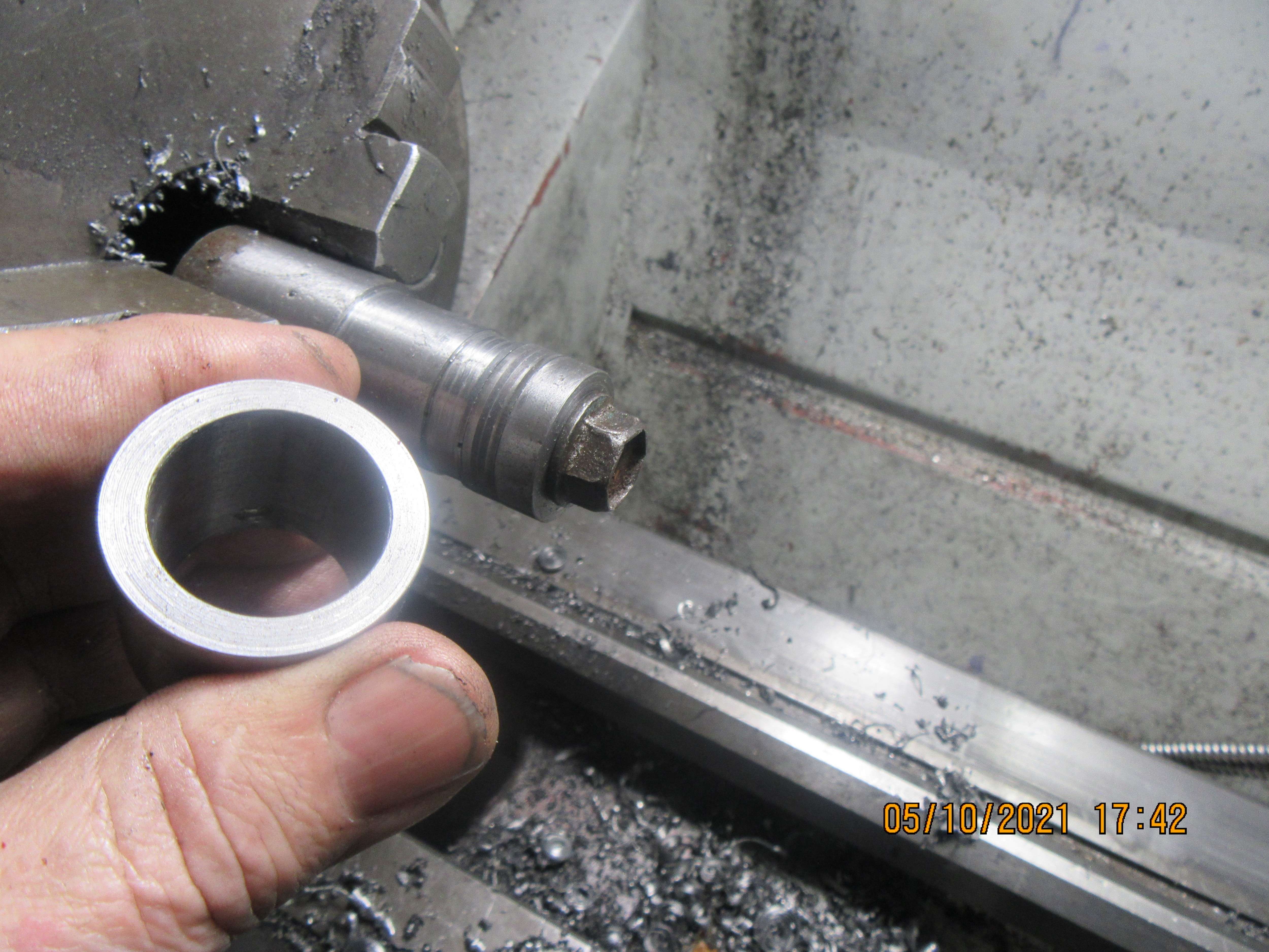
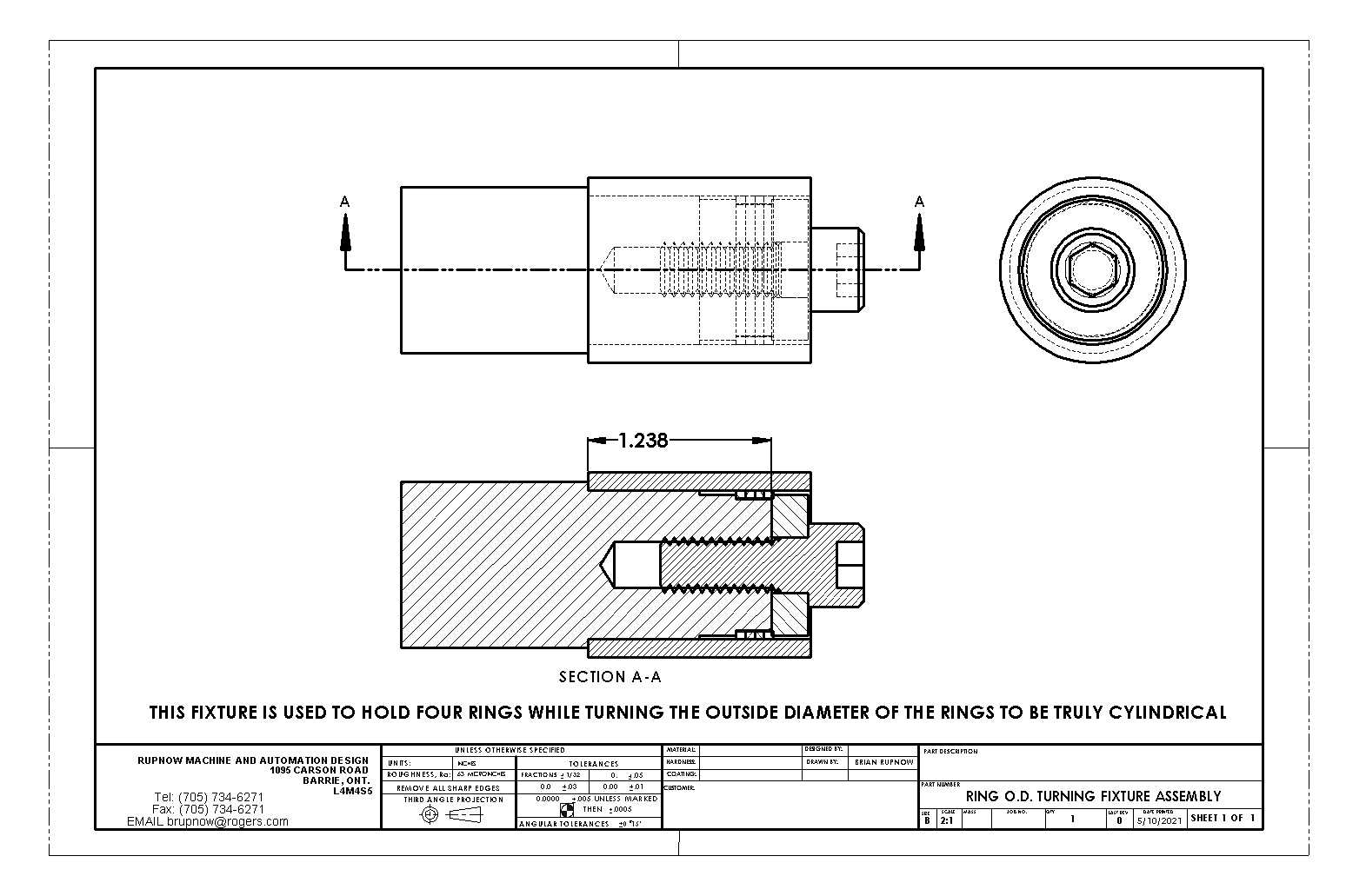
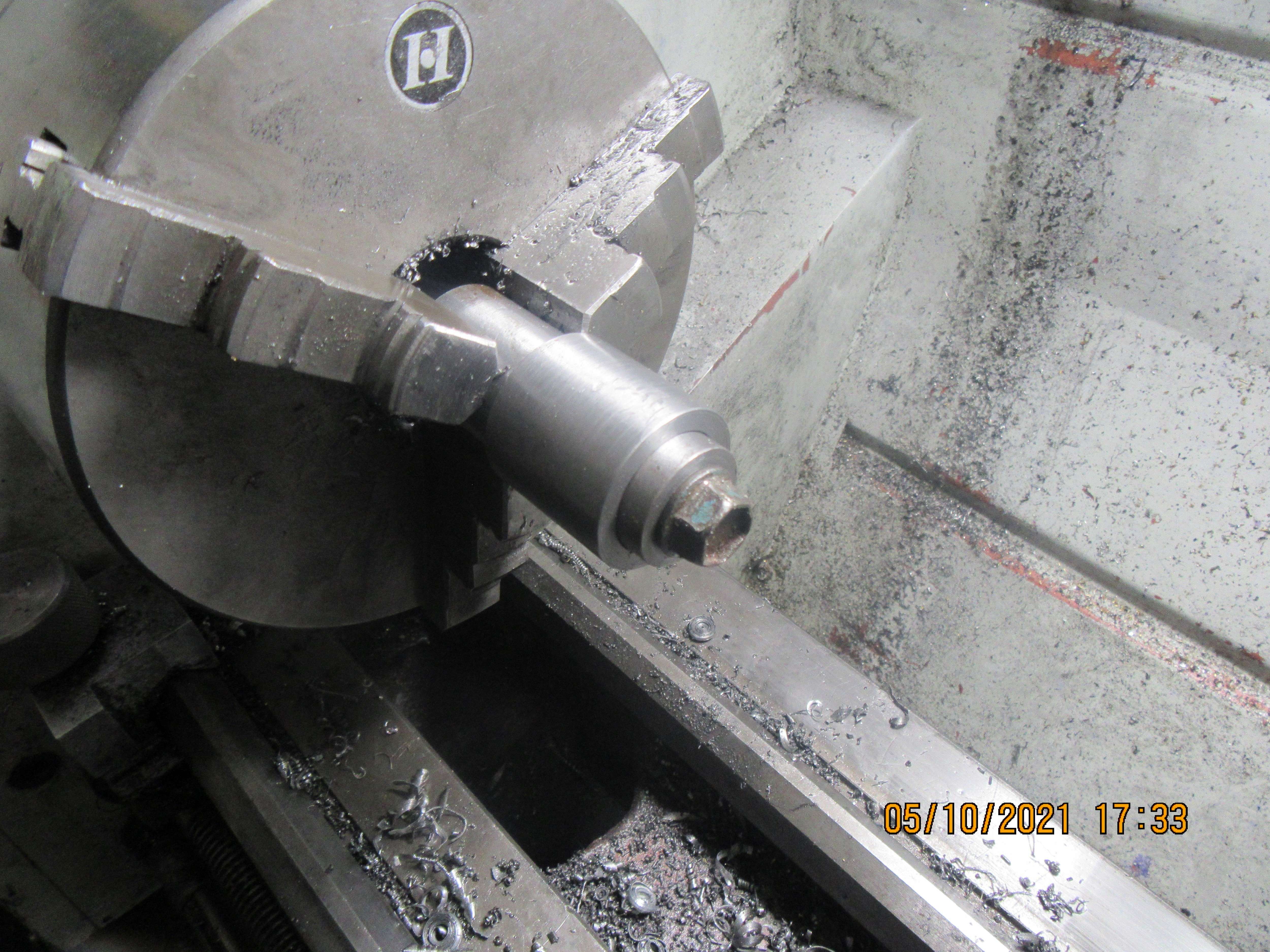
Here we have Mr. Chaddocks fixture for turning the outer diameter of piston rings to make them truly round. The sleeve in my hand has an internal bore of 1.00". The rings are sprung into the sleeve, the sleeve with rings in it slides over the part held in the chuck, then the washer on the very end is tightened down with the bolt, which squeezes all of the rings together. The o.d. of the 1/4" thick washer is slightly smaller than 1", so after the bolt is snugged up tight, the sleeve is slid off over the washer, leaving the rings ready to be turned or ground to a perfect diameter. I am going to use my toolpost grinder to do that.---And no, those aren't the rings I bought from Debolt. Those are rings that I made, and truly, I see no difference between the Debolt rings and the ones I made.
FOb6Rv.jpg

NsxxQs.jpg

rn7bxU.jpg
 
Hi Brian, I believe the reason that the rings did not bed in when running with an electric motor is that you are only relying on the ring tension to apply wall pressure when with the engine running you have the addition of combustion pressure putting pressure on the rings to seat them. John
 
Here we have Mr. Chaddocks fixture for turning the outer diameter of piston rings to make them truly round. The sleeve in my hand has an internal bore of 1.00". The rings are sprung into the sleeve, the sleeve with rings in it slides over the part held in the chuck, then the washer on the very end is tightened down with the bolt, which squeezes all of the rings together. The o.d. of the 1/4" thick washer is slightly smaller than 1", so after the bolt is snugged up tight, the sleeve is slid off over the washer, leaving the rings ready to be turned or ground to a perfect diameter. I am going to use my toolpost grinder to do that.---And no, those aren't the rings I bought from Debolt. Those are rings that I made, and truly, I see no difference between the Debolt rings and the ones I made.
FOb6Rv.jpg

NsxxQs.jpg

rn7bxU.jpg
Hi Brian, been following this intently, one question? If you compress your rings into a sleeve that has the actual finished bore size, clamp tight, and then machine/grind to a “perfect circle”, you must surely be reducing the o/d of the ring to less than the bore size? Would it perhaps be better to start off with a slightly larger diameter ring and sleeve then grind down to the size required? I’m thinking that the ring in the sleeve, before machining, will not be in full contact with the bore 360deg, so will end up smaller after grinding down to the lowest point to obtain a true circle,and when expanded into the engine cylinder, could perhaps have the same issues as before machined. I don’t know, I may be wrong, I usually am.
Doug.
 
Back
Top