A new attempt at making piston rings

Home Model Engine Machinist Forum

Help Support Home Model Engine Machinist Forum:

This site may earn a commission from merchant affiliate links, including eBay, Amazon, and others.
Hi Brian. (Spell check pre-emptied my typing with "Brain").
Another nice bit of work. Next you'll make a dross collector with pipe for attaching your vacuum cleaner, to catch the dressed swarf from the stone. Some of that carborundum dust is smoke fine... (depends on the stone?).
K2
 
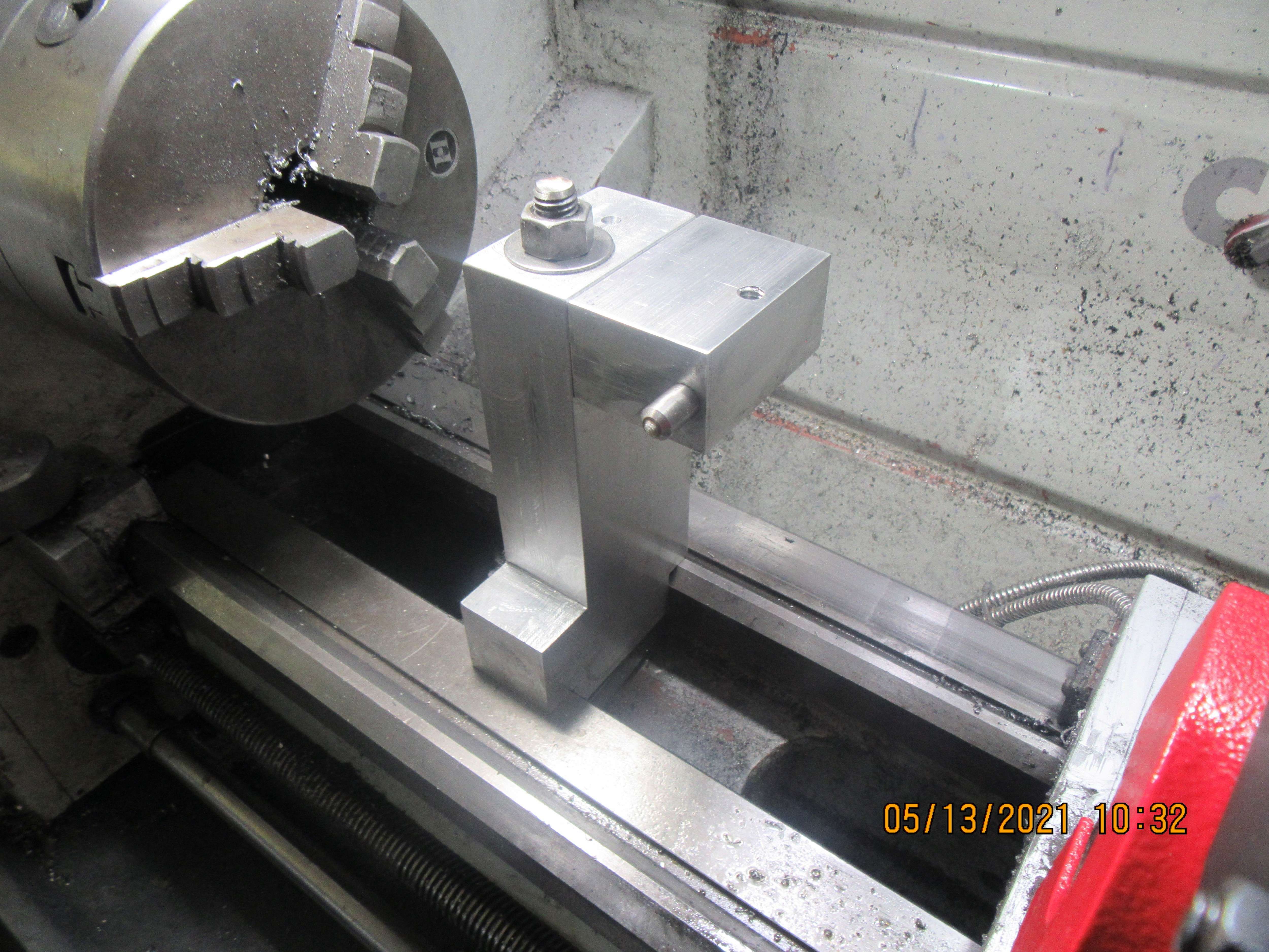
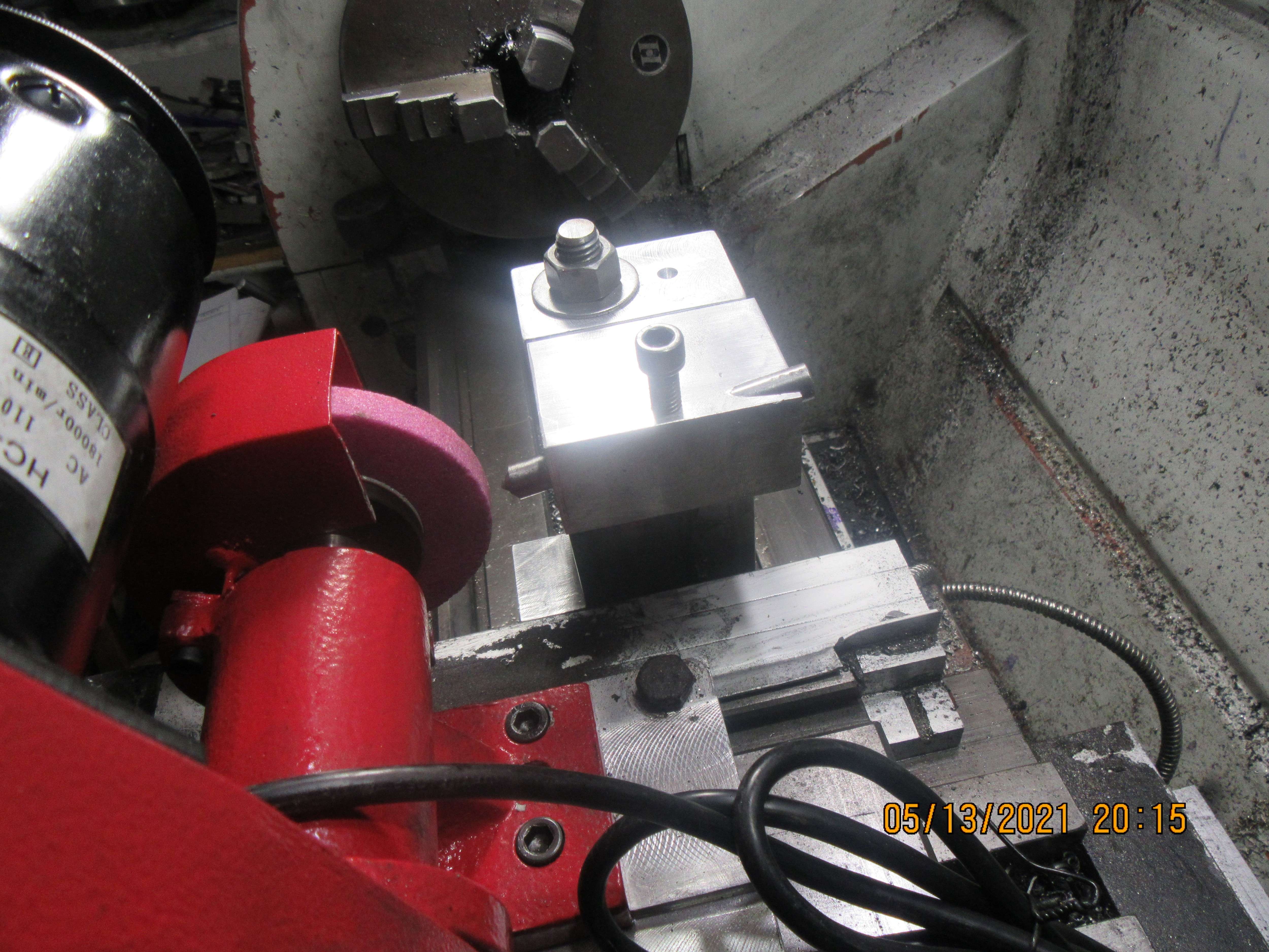
The diamond support tower is finished. It all goes together nicely and locks securely in place. Now I am getting posts that say the diamond support shaft should be tilted down 15 degrees. That is not a major problem, just a bit more work. Are we agreed that the diamond itself should still be on the same centerline as the grinder shaft?
JyqSVH.jpg
 
I am not an expert on tool post grinders but why would it make any difference where the dresser contacted the wheel? The goal is to make the wheel truly round and as long as it contacted the wheel in a straight line it would seem to be able to do that.
 
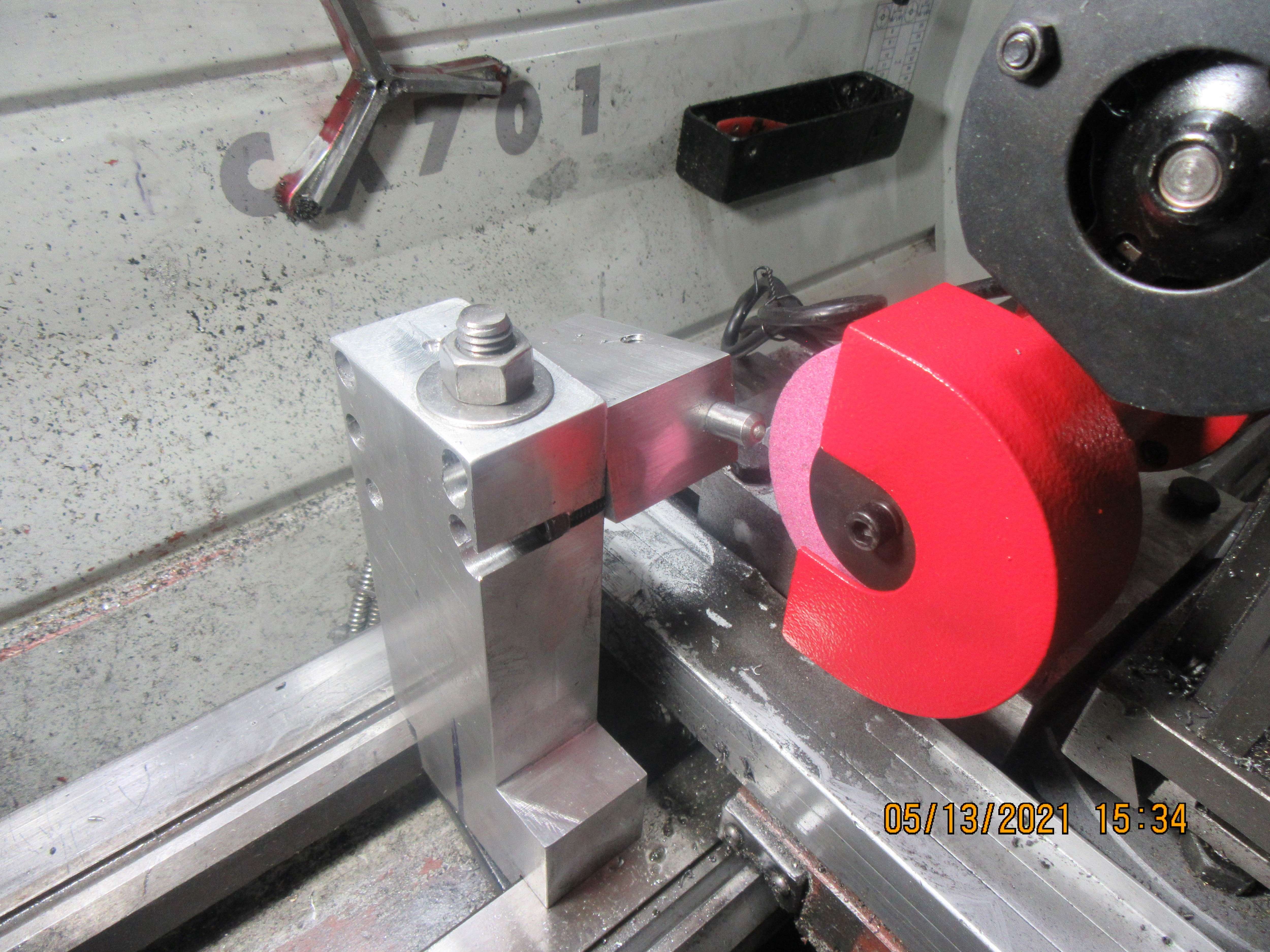
One more time with feeling---This time the diamond support is set at an angle of 15 degrees with the center of the diamond on centerline of grinder spindle and chuck all in the horizontal plane. It isn't quite as pretty as the first time around, but form follows function.
WRQv6d.jpg

0Z3noz.jpg
 
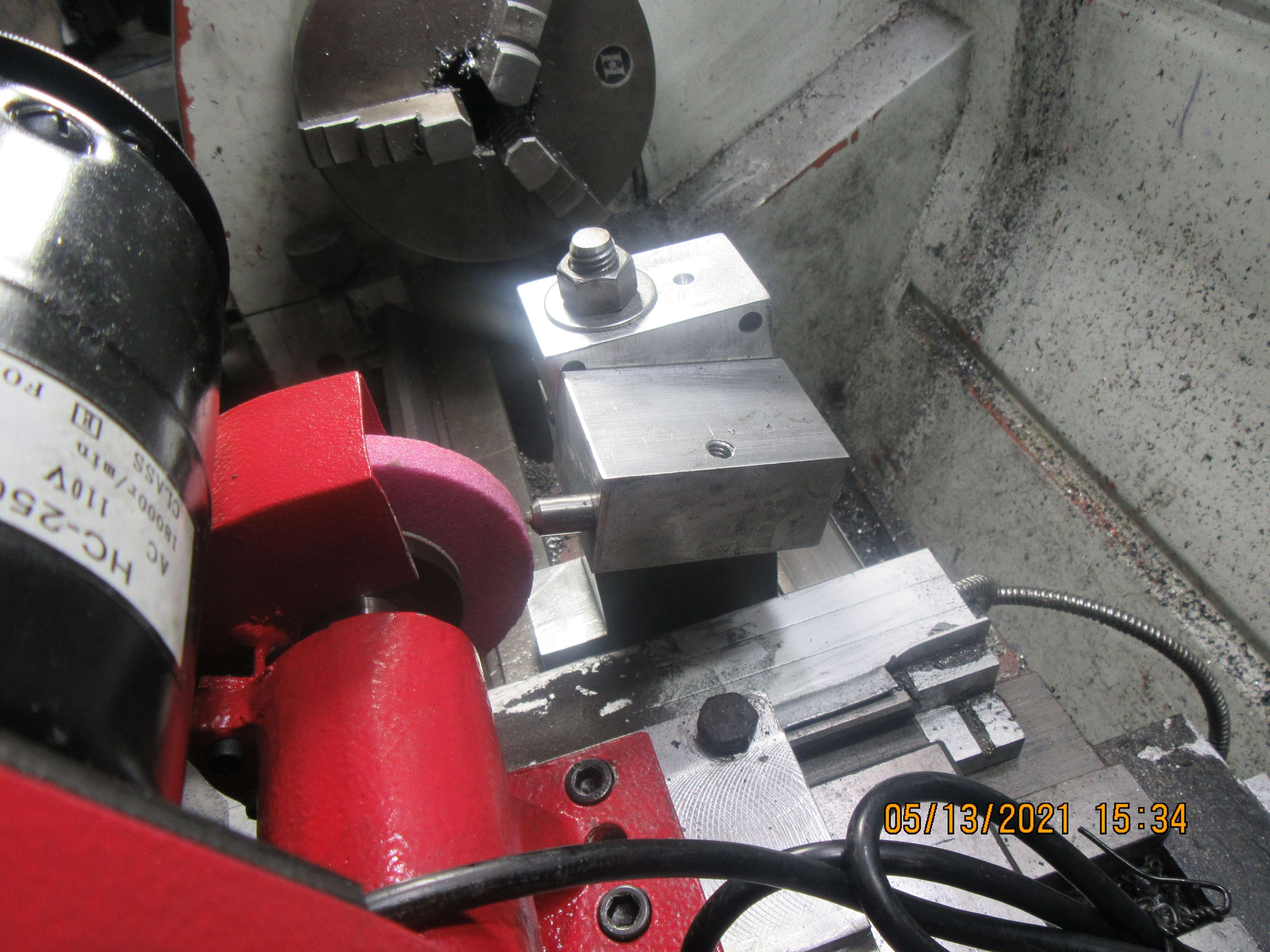
Ahhhh Jeez---Now I'm being told that the diamond tool should be 15 degrees opposite to what I made it.---that it should be angled down at the front where it contacts the wheel.
 
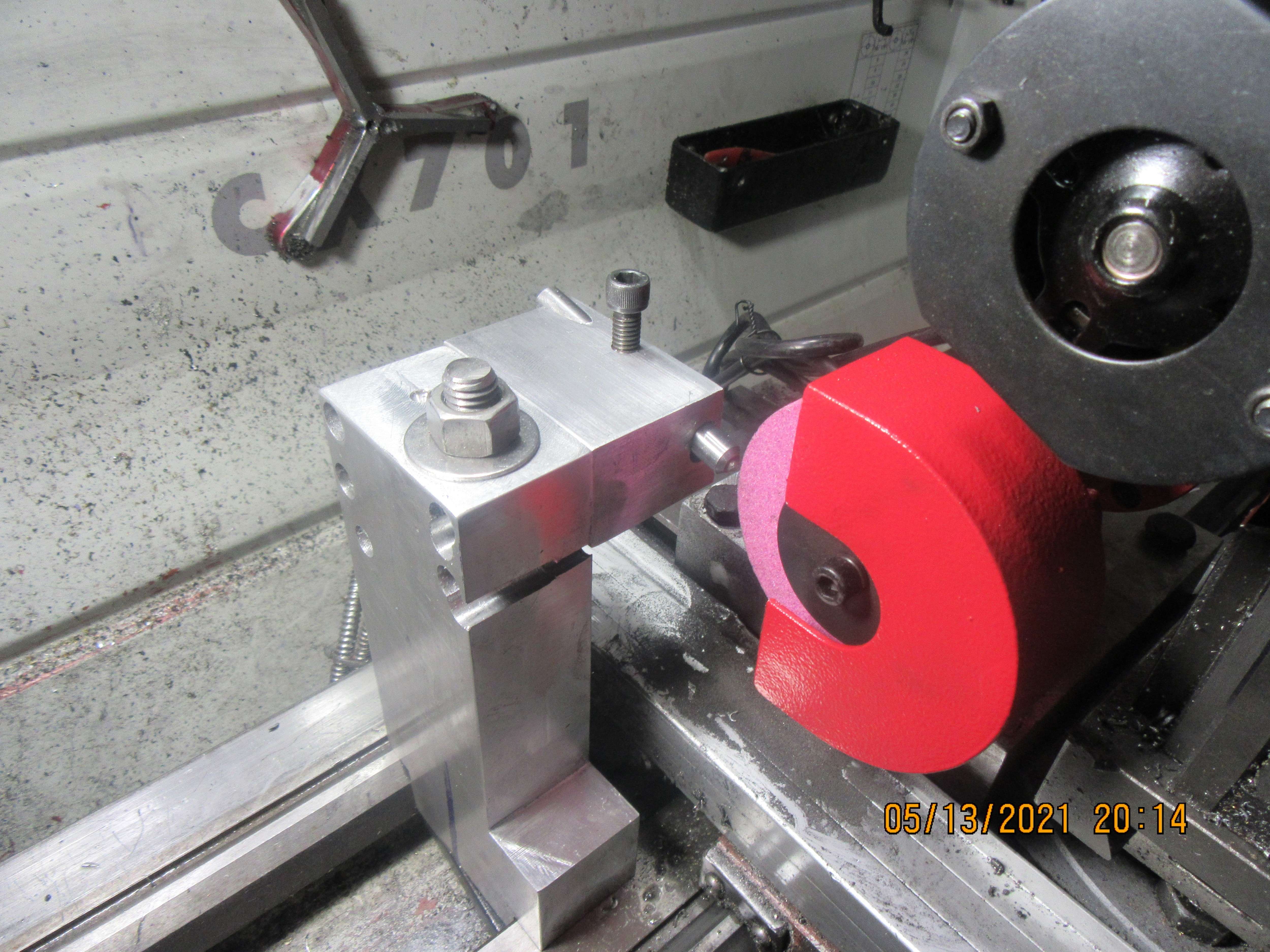
Third times a charm!!!--We're setting at 10 degrees angle and diamond is at or just below spindle centerline. And the moral to this story is Research-Research-Research. I spent two minutes on Google and found all kinds of information about what I am doing here, even drawings. Luckily, I didn't have to make any new fixtures---Just relocated the hole for the shaft which holds the diamond. Anything from 5 degrees to 15 degrees is suitable, so I'm good with this. Arrrrggghhh!!--Let that be a lesson to me.
UiT7fo.jpg

2TuthP.jpg
 
I make my rings +.002 on the o.d. bigger then the bore and ad ,001 for every inch of bore.
The grooves I cut T least .06 deeper then the thickness of the ring
I cut ALmost threw the ring ......put it in a vice with the partially cut edge close to the vice jaw break the ring 90 degrease from the jaw face with an unsharpened h.s.s tool bit and small hammer..........light tap is all it takes .....then with a needle file I fit the gap I need checking it often in the bore ......after the gap is right I put them on a1/4 key stock
Heat the area 180 degrees from the split to blue .......propane is lots ring will stay spread when cool I make my rings 1/8 thick .......they are in a1.25 bore you may have to go smaller on the thickness ....to put them in I slide part in the groove ...remember it is deeper and work around in telling is in ....you will have to compress the rings to get them on the bore ......brass shim and a hose clamp....works ...the force from the ring itself will go round to your bore ..........made lots like this for steam engines and the completion will hold the engine on a ramp while loading .......the depth of the groove s not important the. Seal is made in the fit of the width .......this I fit like you said but I fit the ring to the groove lapping them on a stone in a figure 8 pattern the closer the better ...hope this help it is for steam never tried it on a ignition engine.....if you can find some durabar cast iron it centrifugaly spun gray iron real nice stuff and a bit more flexible if you know what I mean but just gray iron works
 
Last edited:
is that 15 degrees down with the wheel turning clockwise or anticlockwise?
just kidding, maybe, my luck would be that i would buy a grinder for a left handed lathe.
 
Brian
I set up my diamond on center line and no angle. Only when I set up the wheel at a angle I then also angle the diamond point downward at about a 8-10 degree angle
 
Yes no need for angles with that set up the use of angle is more for surface grinder you angle it so it’s behind the wheel incase you dig in it don’t jam up if I make sene
 
Hi Brian, Nice set up to dress the grinding wheel for any future grinding. But why go to all this trouble to make piston rings when following the "Trimble" method in "SIC" will generate perfectly round rings every time. The big wide rings you are using will if not perfectly round will take ages to run in because of the larger surface area.
In an auto engine the ring width to bore diameter is significantly narrower and bed in quickly. In my case I halve the width as determined using the "Trimble" formula and fit two rings with the gap at 180 degrees apart in each grooves. A couple of revolutions of the crank by hand and I get full compression after first run.
I machine the rings to .001 over bore size split the rings on a tapered mandrill and heat treat in the crucible as per the "Trimble" dimensions, and then gap the rings according to bore size. Hope this helps Brian. John Samphier
 
Johwen---I have been a complete failure at making my own rings. I have tried more than once and not had any success. In 40 engines I have built, I have never made a set of cast iron rings that worked, only used Viton, which gives instant compression. I have two engines running with purchased cast iron rings and they work fine. The third set of purchased rings as used on my Vertical i.c.-2021 don't seal worth a damn, although it runs fine with a Viton ring on it. I've decided that the next big milestone for me is to master ring making, so I've spent a bit of money for the grinder and heat treat oven.
 
I have purchased two sets of rings in the past. One set was for a 1" bore engine, and one set was for a 1.25" bore engine. They both worked "right out of the box" with good compression and both engines ran fine. The third set of rings I purchased for my current vertical i.c.-2021 engine didn't work---. Absolutely no compression in an engine that ran just fine with a Viton elastomeric ring. I don't do compression tests other than "can I feel it when turning the engine by hand". I don't do leak down tests. The only other tool I have at my disposal is a fitting that screws into the sparkplug hole and lets me put air pressure into the cylinder with the piston at top dead center on the power stroke. That lets me diagnose the intake valve, the exhaust valve, and the rings. In all of the forty engines I have built, the rings are the only thing that I have not mastered. I've spent about a thousand dollars in the last three weeks, buying equipment to let me know that my "process" in ring making doesn't have some flaw. I keep hearing from others who make rings and have no trouble with them, and I certainly hope that I will come up with a repeatable process for making 1" diameter rings that hold compression.---Brian
 
Maybe it's your cylinder.? Honing (with a brake hone etc) won't correct an out of round cylinder. It may even make it worse.
I know you said you tried the light trick using the mask etc. But it's a very tricky process with a very bright point source of light where you try to aim the light at the cylinder/ring interface while moving it and your head around as if you're trying to bounce the light around the ring - so to speak.
 
dsage--You could be right. I found that holding the cylinder up to a bright light and looking for gaps between the ring and the cylinder to be very difficult. That engine runs great with a Viton ring, but a Viton ring is probably more forgiving than cast iron rings. I reached the point of not knowing what to do (that happens more often than you would think). I decided to just walk away from it for a while and concentrate on getting a toolpost grinder and a small heat treat oven to help me make better rings for future engines. The rings I'm currently using are purchased rings, and I made a new piston to suit the rings. Once I get my new equipment all up and running I will revisit the issue. Might make a new cylinder. Don't really know quite yet.
 
Brian
Going back through the post I seen were you stated you had honed the cylinder smooth so you could run orings. Is it possible you have taken out all the crosshatch and the bore is to smooth you will never seat rings if the bore is to smooth. Maybe it’s time to look at all the basics first. Your cylinder would have to be way out of round before it would loose enough compression not to start. But if there is no crosshatching on the bore it can be a total lose of compression. And when you added oil to the cylinder it would seal the combustion chamber and of course give you compression. Just making you think of some other things
Thanks
Tom
 
Sorry Brian, I am trying to teach an expert here, but I guess you have blued the piston, slid it through the cylinder and checked contact? Then, assuming the cylinder is OK, I would blue the bore and try rings to see contact points...?
I have never done this but it seems like a good idea.... ?
I have blued valve seats and valves....but I assume you have already eliminated valve leaks?
Have you tried soapy water around the cylinder head joint when spinning the engine? - I had a 2 stroke motorcycle twin that blew the gasket under full load (made a load squeak!), because the studs didn't have enough pre-tension. Increasing the torque 10% over the book value cured that! I also experienced an engine where the head was tightened onto a casting flaw, preventing the load being applied to the head gasket. Soapy water found that!
Enjoy "the Search for the lost compression".
K2
 
Back
Top