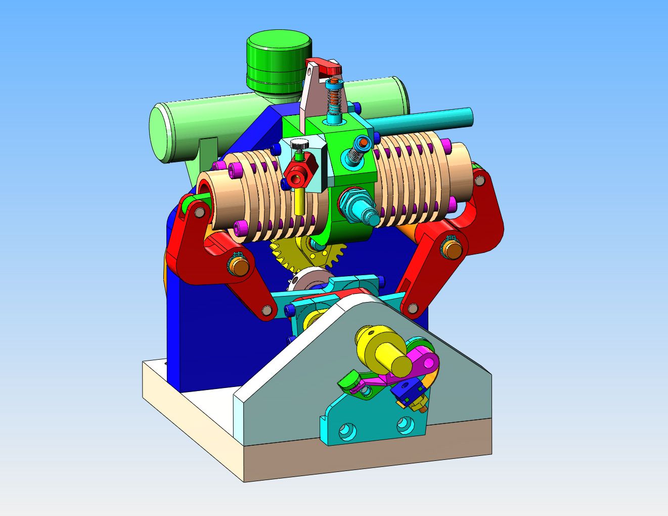
A different opposed piston engine---

Home Model Engine Machinist Forum

Help Support Home Model Engine Machinist Forum:

This site may earn a commission from merchant affiliate links, including eBay, Amazon, and others.
Hi Brian,
Slightly off topic. Are you aware that you can extract small 6mm dia or there about's, ball bearings from scrap 80mm computer fans. The fans often seize up but its usually the sleeve bearing that fails in this way. Also some fans have two ball bearings. Since these fans are just thrown away they are usually free for the asking.

PS. Following your build with interest.
 
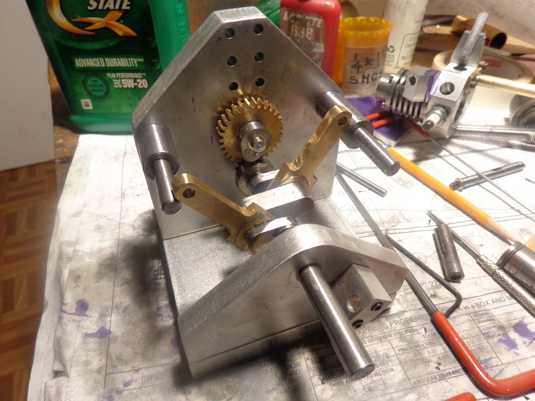
In this picture, you can see that I have Loctited the bushings into the front and rear crankshaft support plates and inserted a "guide rod" that I know is straight before tightening the bolts down that hold the plates to the base. I will let it set up like that overnight. I have also silver soldered the ring onto the small crankshaft gear and you can see it setting on the crankshaft in the foreground. The reason for the soldered ring is this---The gear in its stock form allows a hub with only about a 1/16" thick, not enough to hold set screws. I made the ring a separate piece, and drilled and tapped it for two #8 set screws. Then I silver soldered it onto the thin-walled hub of the gear, drilled and tapped a second time through the thin wall, and end up with a good solid hub to hold the set screws which position the gear rotationally on the crankshaft, without having to drill a hole for a dowel pin thru the crankshaft to hold the gear.
 
The Loctite was completely set up after about 3 hours, so I just had to drop the crankshaft into place and see if it would turn. It does!!! There are a couple of stiff spots in it as it turns, because the crank is not 100% "true".--That's not a show stopper, because none of the cranks of this style that I have built are completely true, and the engines all run fine. I will "run it in" with my electric drill to loosen up the bearings a bit, and it should (we hope) be fine.---and the timing gears mesh fine.--That is always a concern, because there is no adjustment on the hole centers for the crankshaft and timing gear shaft.
 
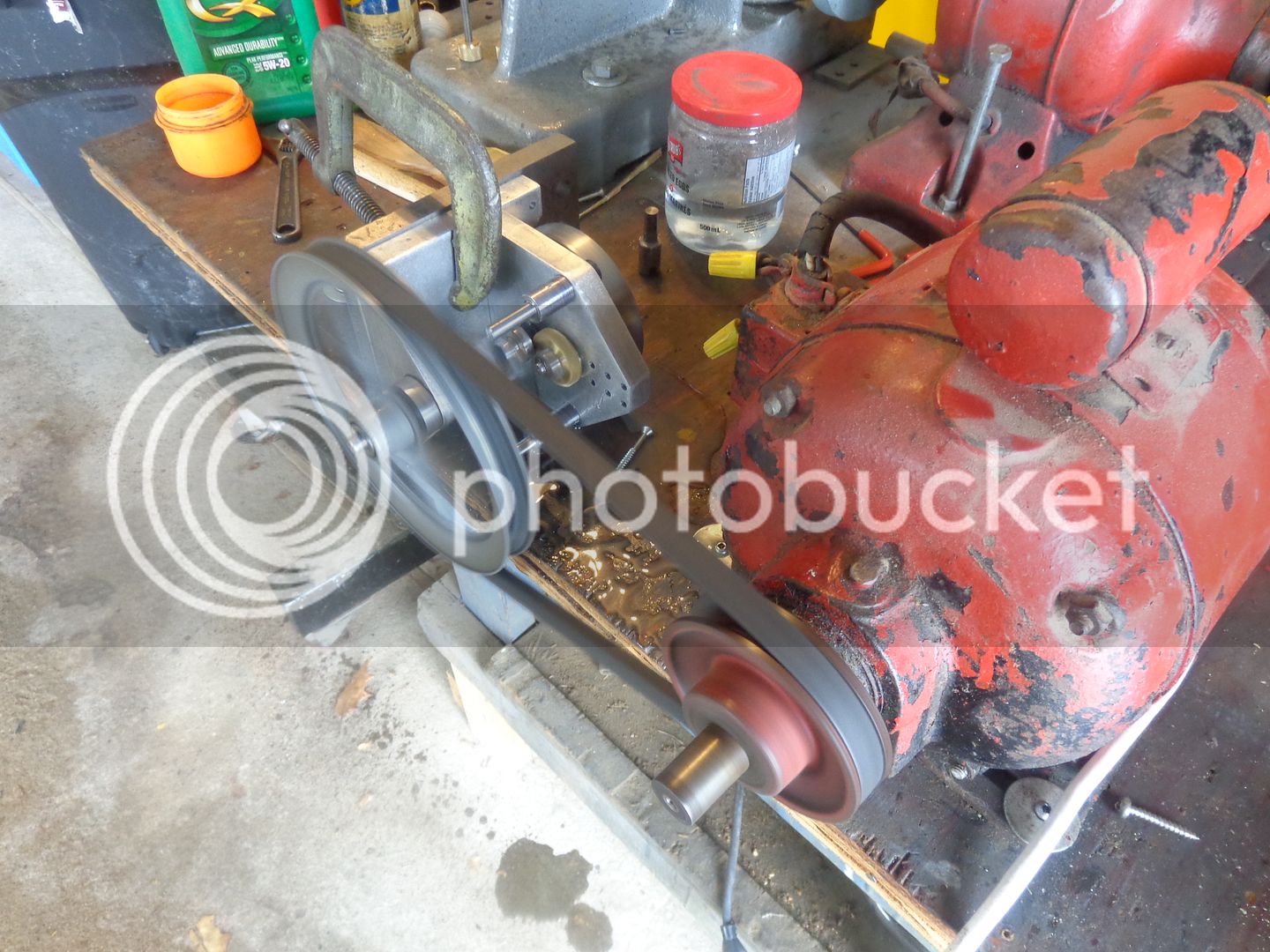
So---Here we are "running in" the crankshaft. I suppose that if I were a perfect machinist, I could skip this step, but you work with what you got!!! When everything is assembled, and all the bolts snugged down, the crankshaft binds like hell. That's due to a host of reasons i.e.---stacked up tolerances, plates not being perfectly 90.0000 degrees on the bottom---a crankshaft that has a bit of "oink" in it. What this "running in" does is wear away the major binding points on the brass bushings supporting the crankshaft. I keep A LOT of oil slathered on while this is happening, and let it run for about an hour. By the time it is fully run in, a baby's breath will turn that crankshaft. I put both the timing gears on as well, figured they could run in at the same time. You will see that I have the front bearing support set up so that I can access the bolts which hold it down to the base plate. I start out with these bolts fairly loose, then every 10 minutes or so I go out into the main garage, add a bit more oil, and snug the bolts down some more. Keep repeating that until the bolts are fully tight.
 
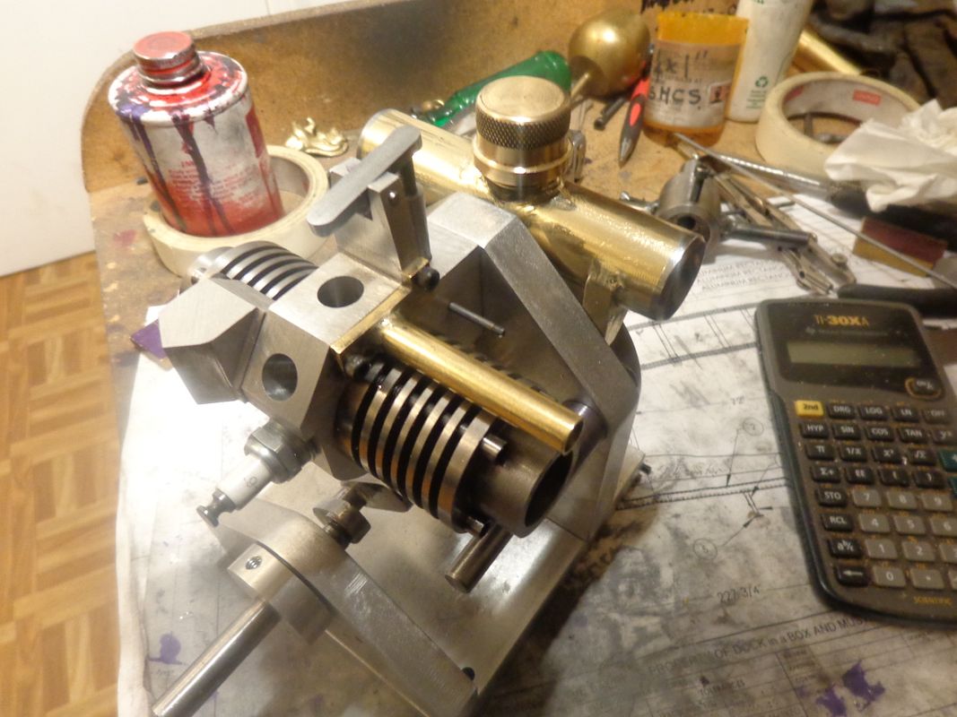
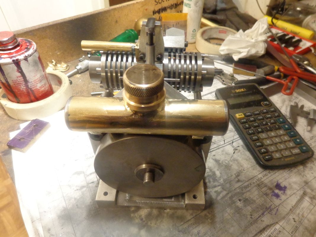
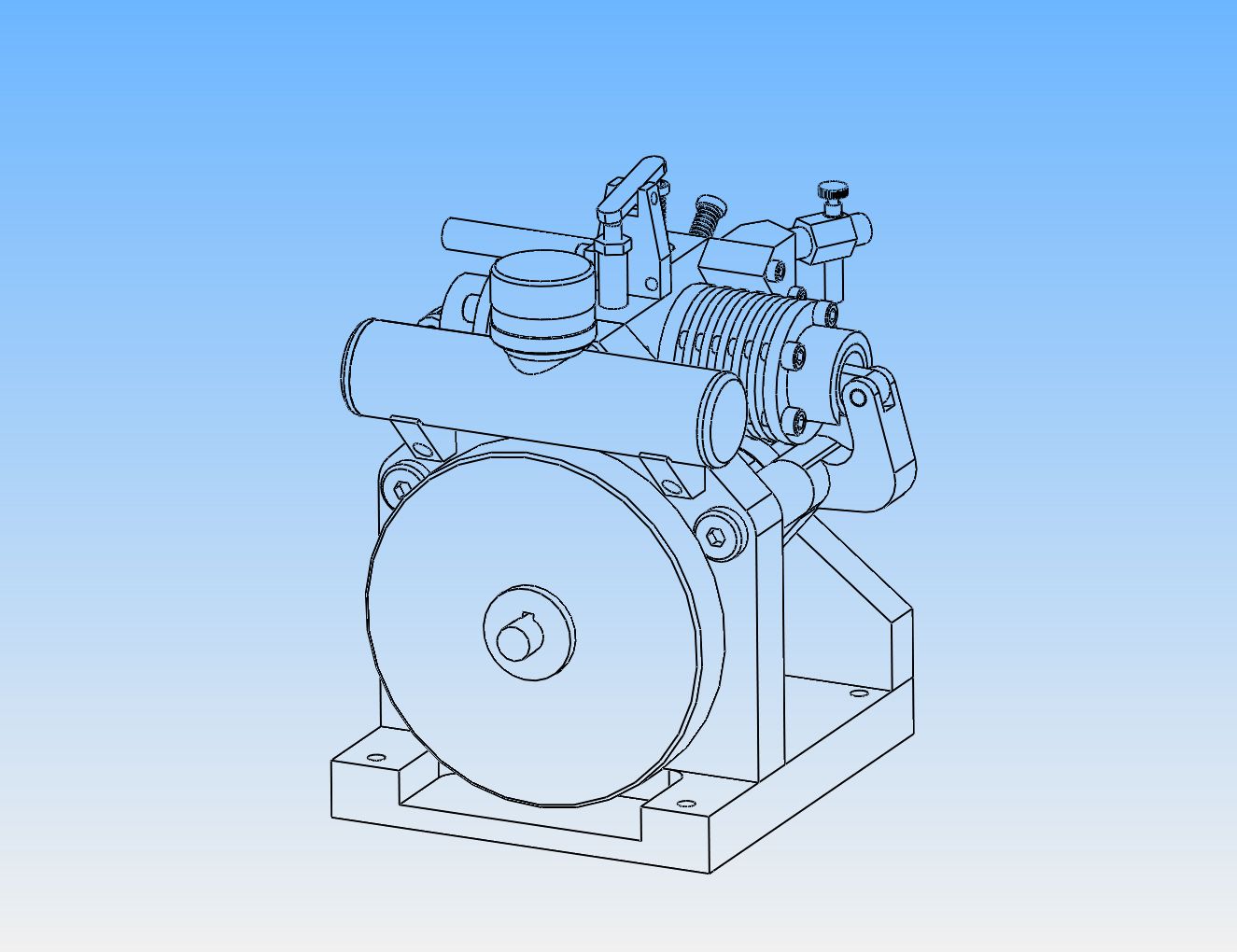
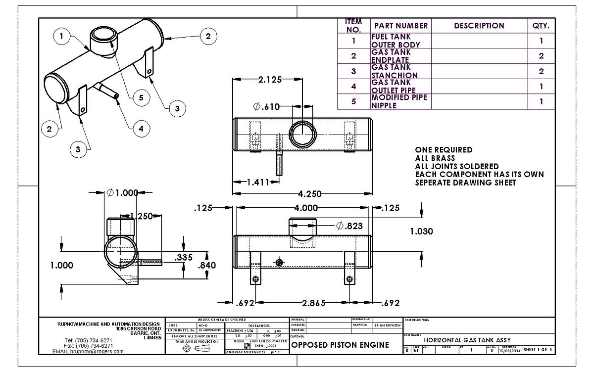
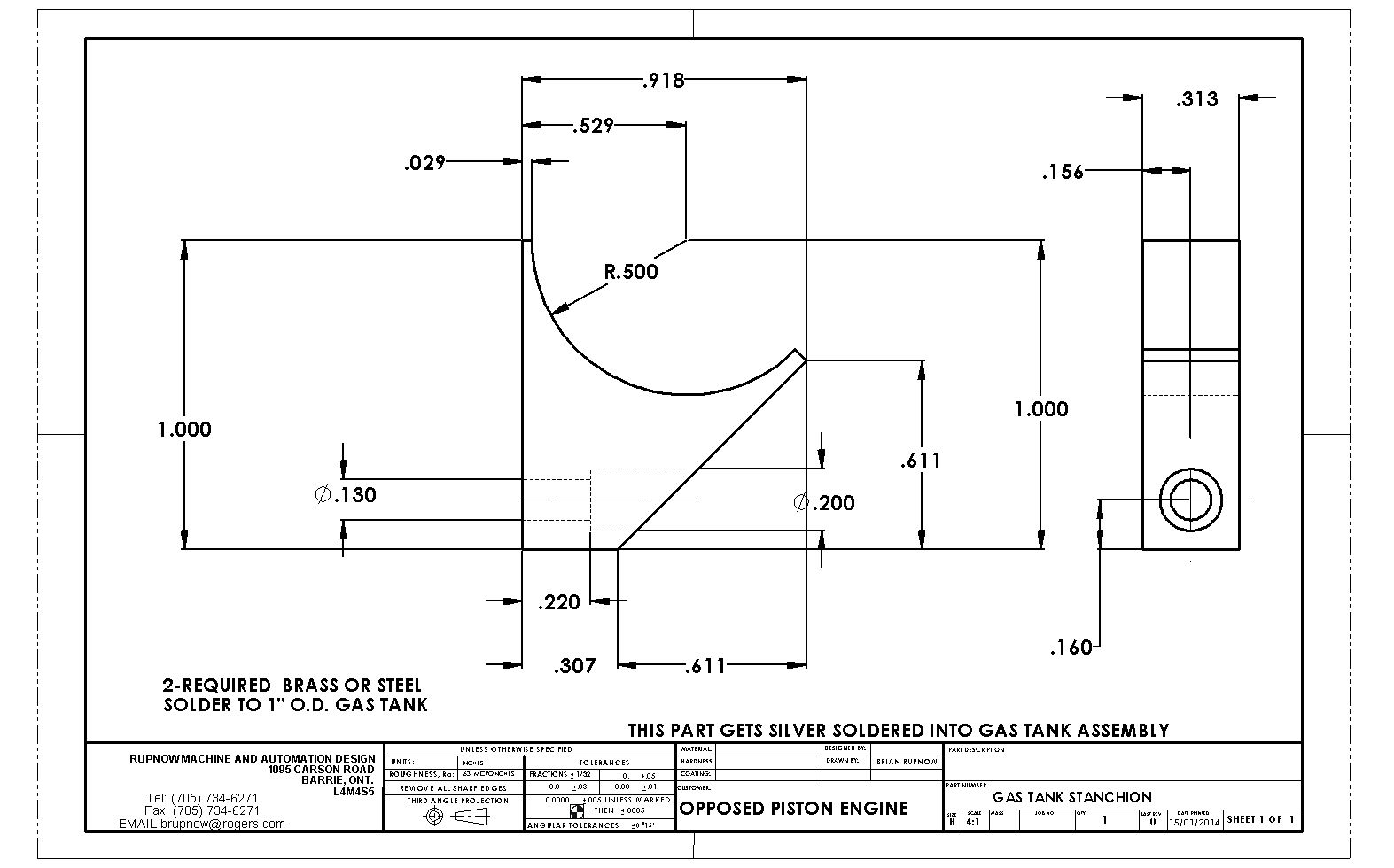
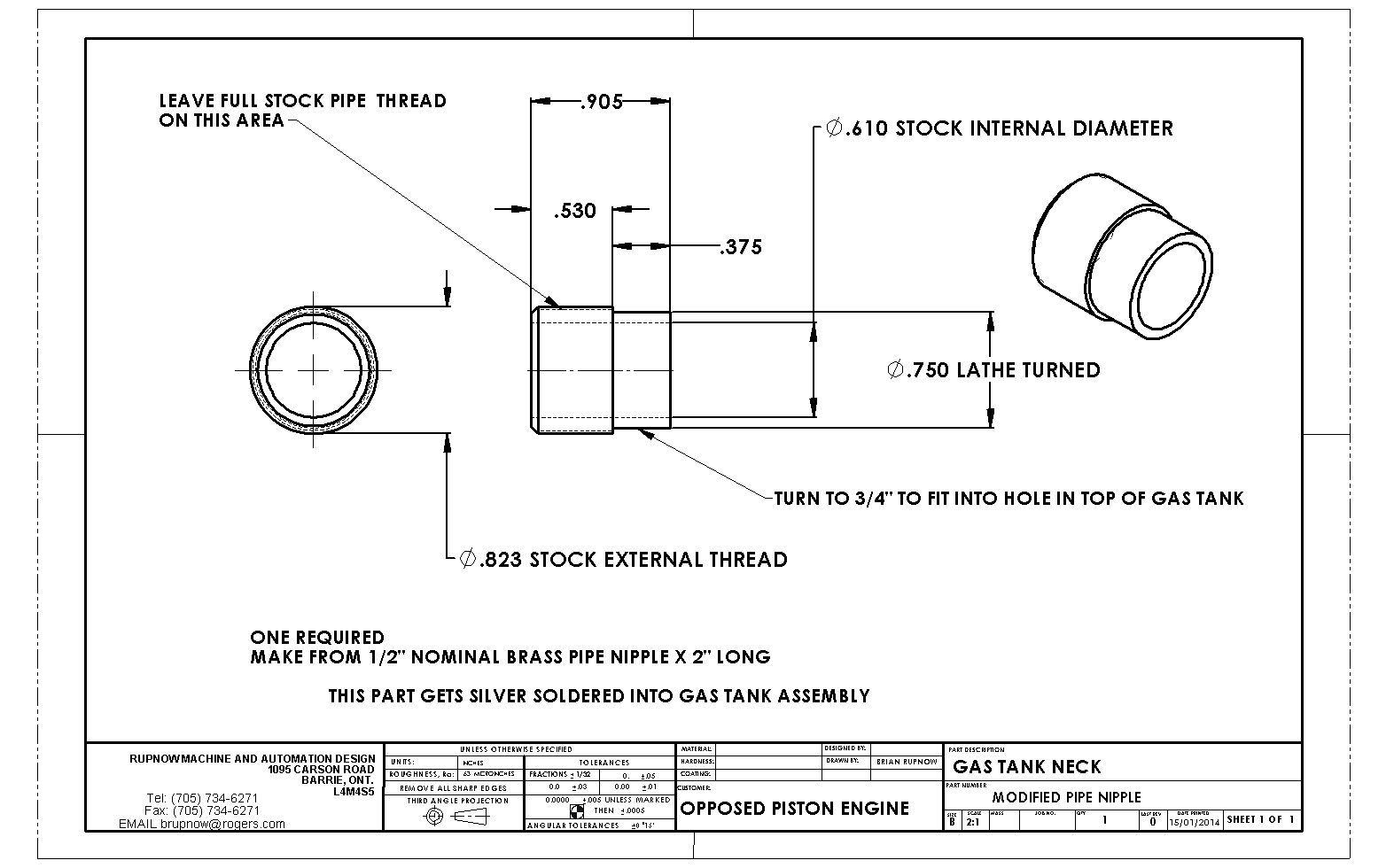
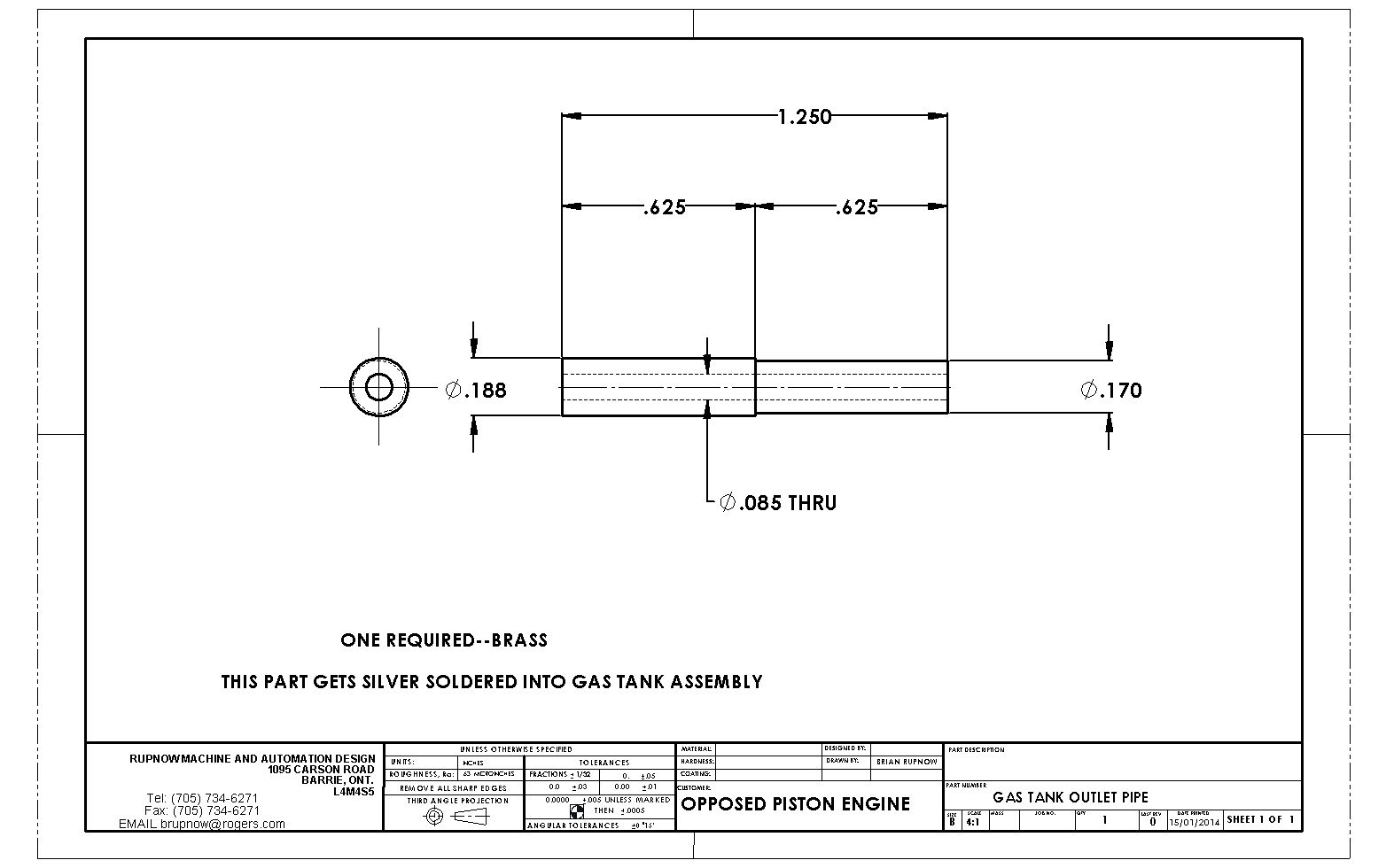
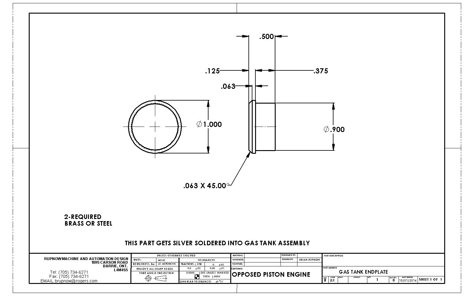
I can hardly believe it!!! All of the mechanical parts are finished except for the valves and guides, and the carburetor. JWCNC--If you were serious when you offered to make the two arms for me, I need them now!!! I have been messing about making gas tank parts, and hope to fab up the two ends and get everything soldered together this afternoon. I haven't been happy with the small size of filler caps and necks that I have fabricated on previous gas tanks, so with the help of a couple of commercial plumbing parts I am going to do something a bit different this time. That nice screw on lid with the knurl on it was a cast brass pipe cap before I committed a little lathe work on it.
 
I'm sure you guys have all heard reference made to "The Good, the Bad, and the Ugly"!!!--Well this is the "Ugly" stage. We have passed, or fortunately missed the "Bad" stage of things. It would only have been bad if, after all this silver soldering it had leaked somewhere. Now, with various files, sanding strips, etcetera, I hope to turn this into the "Good". --I love my new filler cap and neck. It not only gives me a bigger hole to aim for, it also lets me see so I can stop pouring before the damn thing is overfilled with fuel running everywhere!!
 
Well there!!! That's good enough for the girls I hang around with!!! Polishing is a dirty, dirty job. I look a bit like ***** the racoon.


That's a lovely bit of brasswork, very nicely fettled and polished. It the exhaust pipe and the flywheel would look spectacular in chrome !
 
Before I rush out to spend $100 on a cdi ignition, I want to make sure this engine is going to run. I still have a set of points and two 12 volt coils here, and a points mounting block left over from the Rupnow Engine. For the sake of two drilled and tapped holes in my front bearing support plate, I think I will give the points a try first. I'm not quite finished with the engine yet. JWCNC has confirmed that he is indeed working on the two links for me, and I have to now make the valve guides and valves.
 
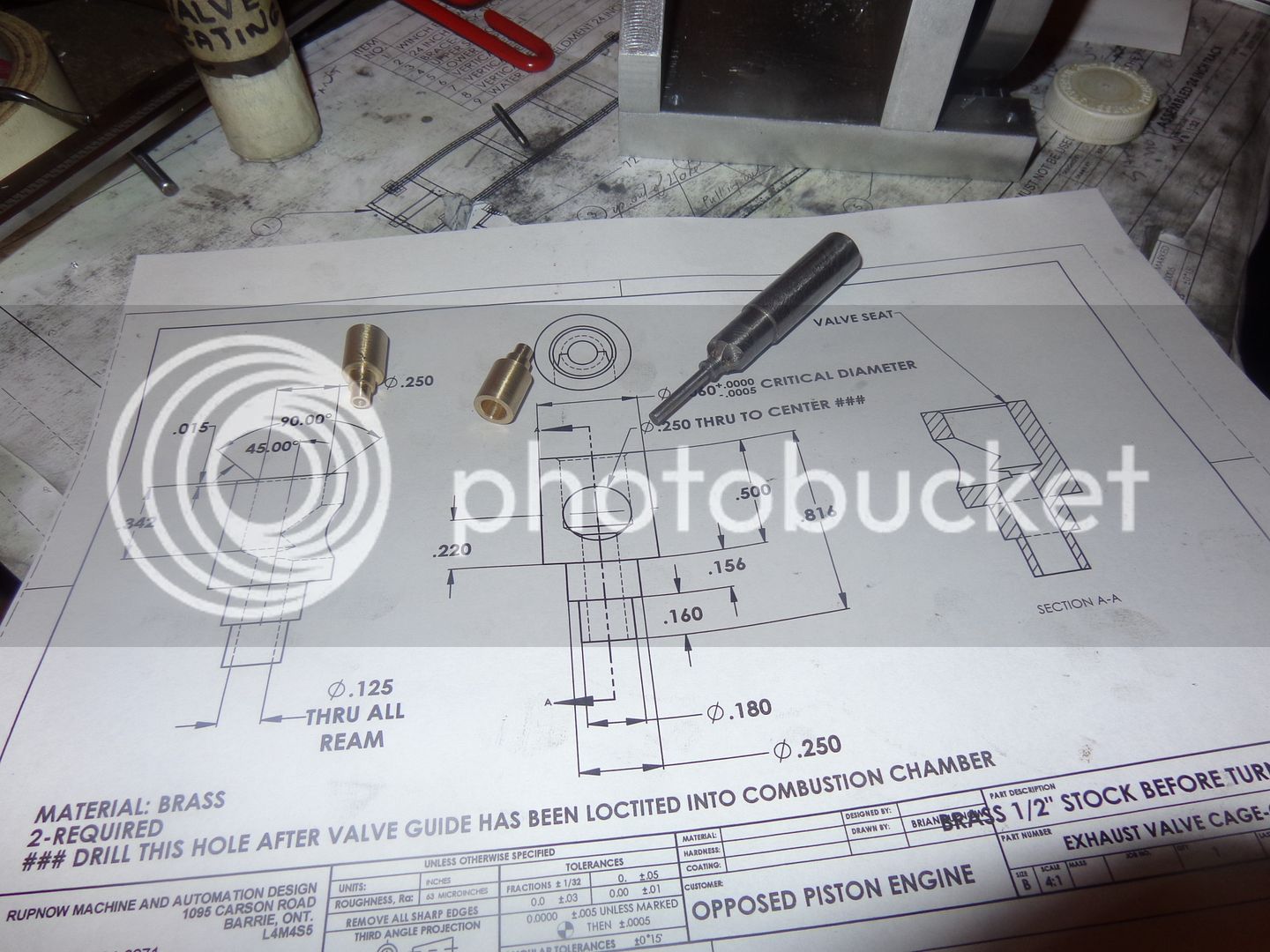
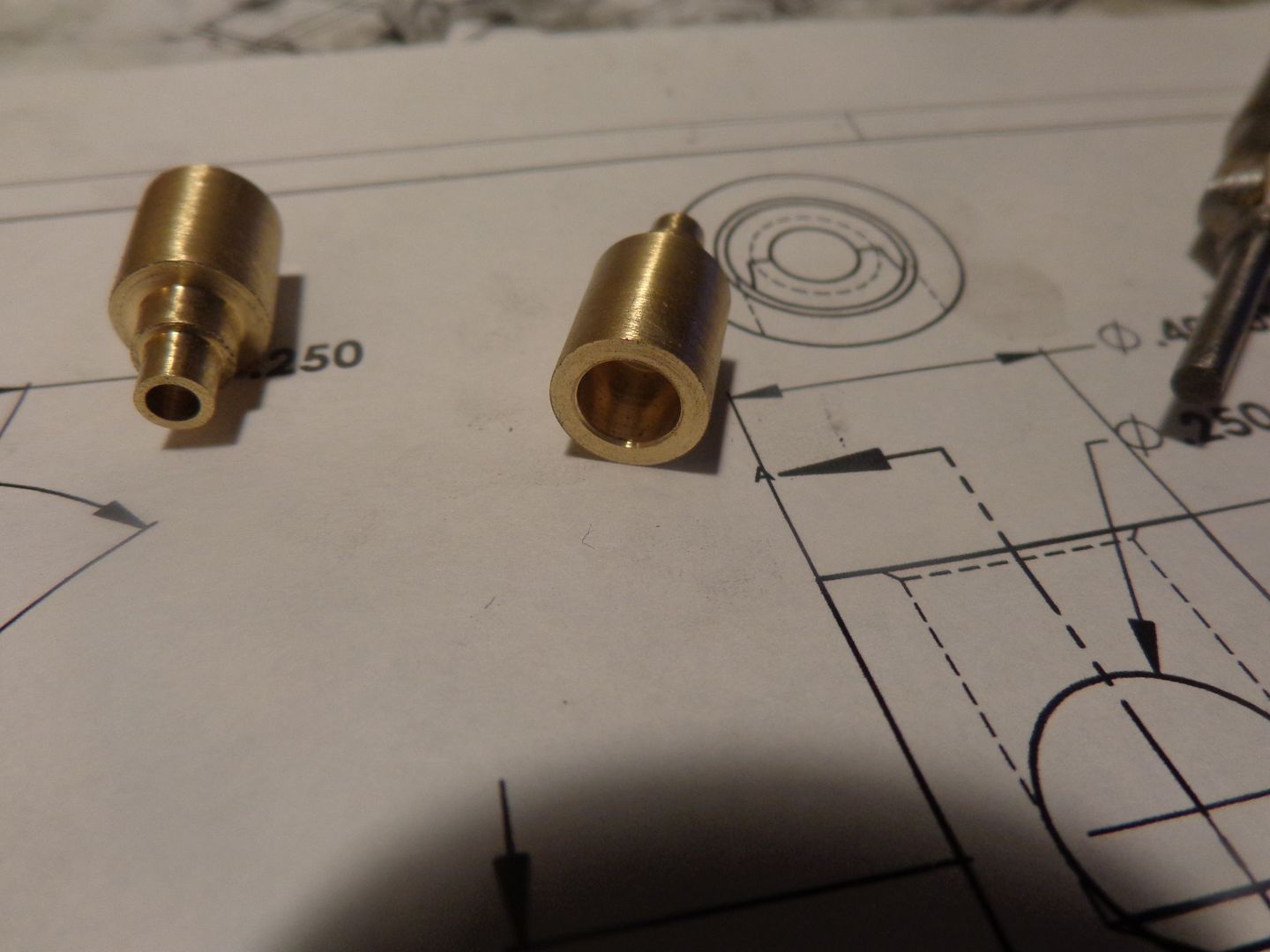
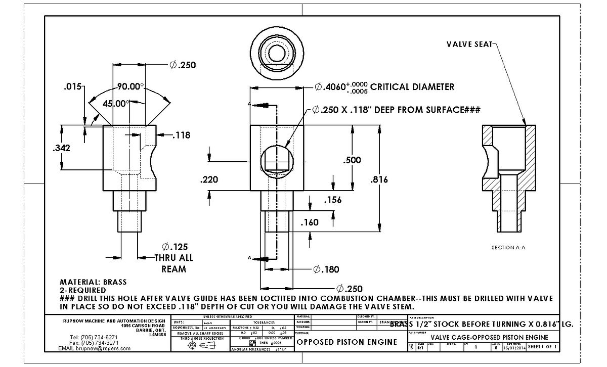
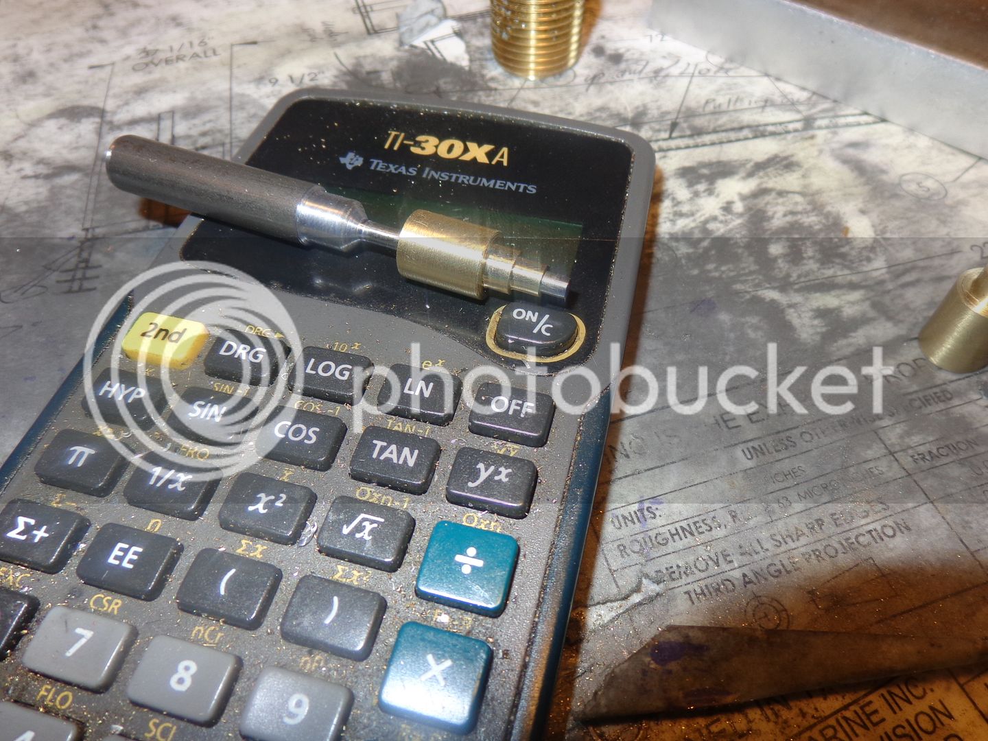
Both valve guides are finished. The steel tool in the picture is my "seating tool". I don't try and put the 45 degree angle valve seats in while the guides are in the lathe. I drill the 1/4" hole in one end, drill and ream the 1/8" thru hole, then take the guides out of the lathe and use the seating tool by hand to put in the 45 degree valve seat. The seating tool has a 1/8" diameter extended nose that fits the reamed hole in the guide, to ensure that the valve seat is concentric with the 1/8" diameter reamed hole that the valve fits into. The actual "seat" area is very small--about .015".
 
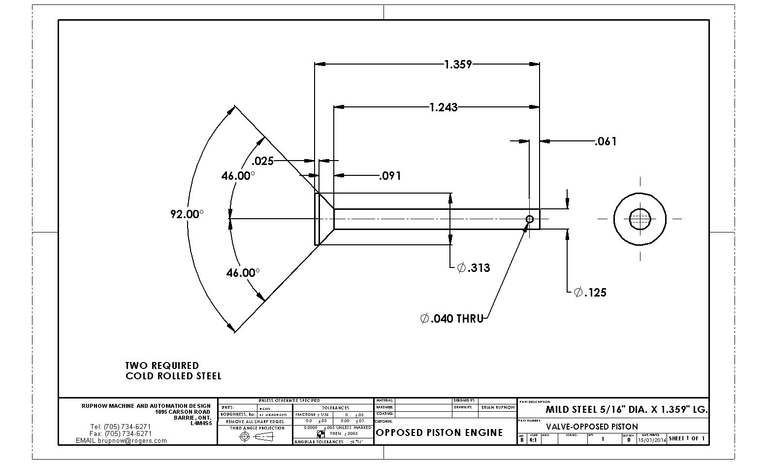
These are details of the valves and valve cages for the engine. Exhaust and intake are identical. I have to check back through the thread and see if I have posted these before, because they have changed.

 
Valve #1 is machined. It fits the guide well. That's because I must have shut the damn lathe off 300 times to "check" for size so as not to go undersize and ruin it. I machine about 3/8" of length at a time, taking it down to 0.129" diameter. I'm afraid to take it down any farther than that. After I get the full length machined, I take it down the rest of the way with #220 grit paper.--I'm surprised that I haven't worn out the on/off switch on my lathe---Yes, you can sand it undersize too--I know!!!
 
Someone on another forum has asked-"Will I press fit the valve cages into the center block, what kind of Loctite will I use, and why do the ports have to be drilled into the valve cages with the valve in place?"---This was my answer---
--I will use #638 green Loctite. No, it won't be a press fit. My only experience with pressing valve cages into place ended in disaster--they both distorted so badly from being pressed into place that I had to remake them. As to why they have to be drilled with the valve in place---I only just discovered that today. On a conventional engine, where you can remove the head, it is no problem to remove the valve and drill thru the side of the cylinder head and the valve guide at the same time after the valve has been removed. On this engine, the valve has to be installed in the valve cage, then the valve cage Loctited into the center block. Once the valve guide is in place, there is no way to remove the valve!!! Not a really good design, and I just discovered it. Its too late to go back and change things now. It should work okay, but I want to be very sure the valve is sealing good to the valve cage before I Loctite it into place. Also, you will notice that other than the Loctite, there is nothing holding the valve cage in place. On conventional engines, I put a bit of a "head" on the valve cage and install it from the inside, so compression can't pop the whole cage assembly out. I can't do that on this engine, but I have a plan to get around that. I also have a plan for testing the "leakage" of the valve to cage seal before I install the valves and cages in the head, and I will post about that when I get to it.
 

Latest posts

Back
Top