90 degree V-twin engine

Home Model Engine Machinist Forum

Help Support Home Model Engine Machinist Forum:

This site may earn a commission from merchant affiliate links, including eBay, Amazon, and others.
I didn't get a lot accomplished today. I was over at my friend's shop using his cutter grinder to touch up a box full of end mills.
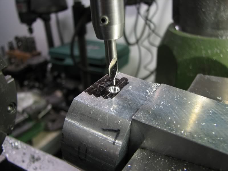
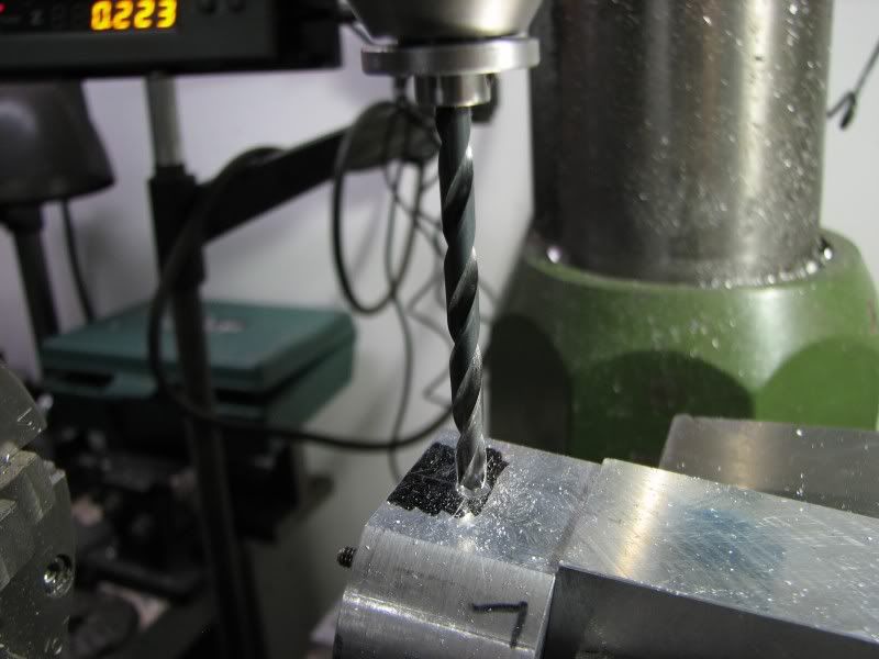
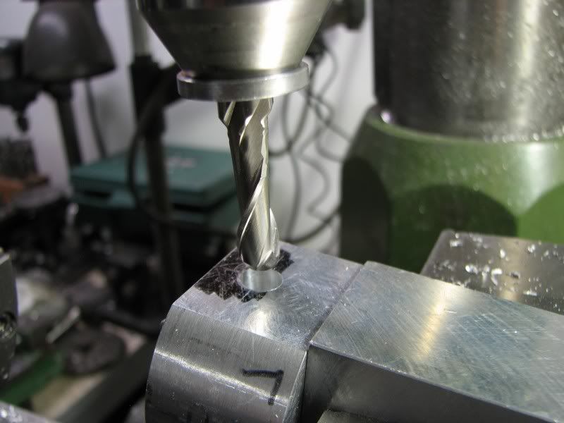
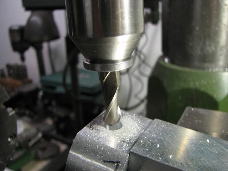
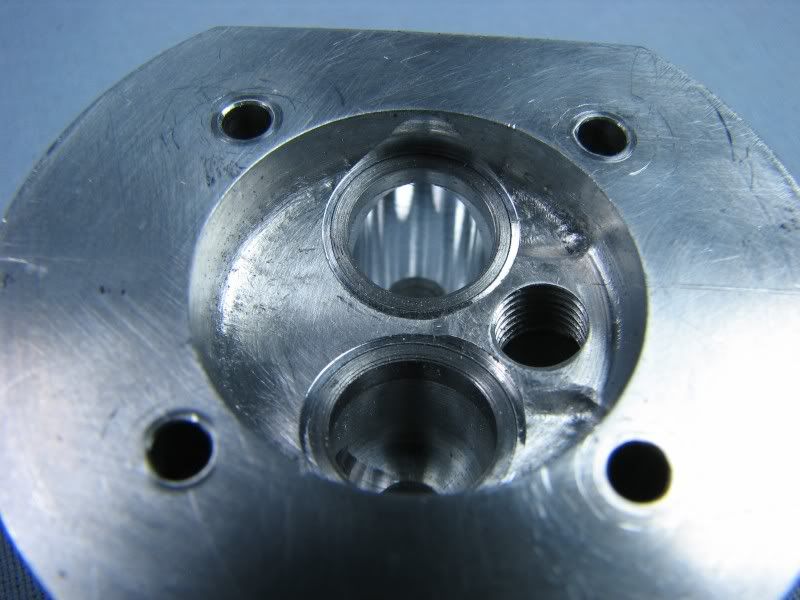
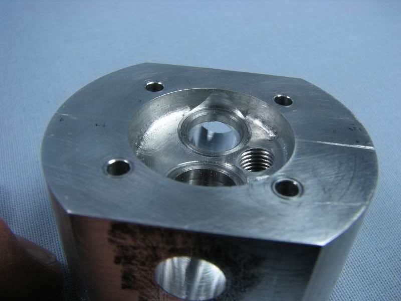
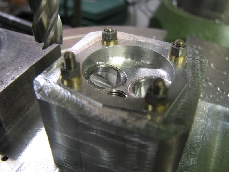
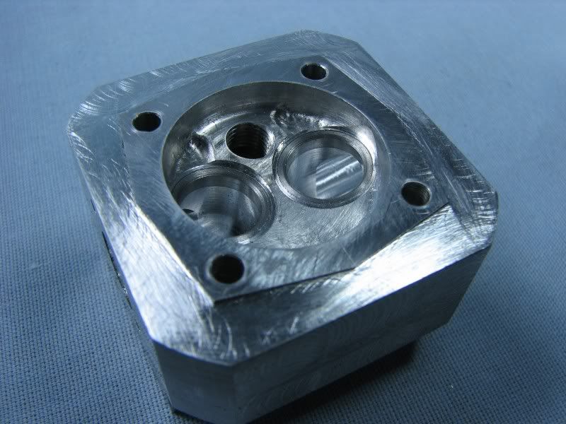
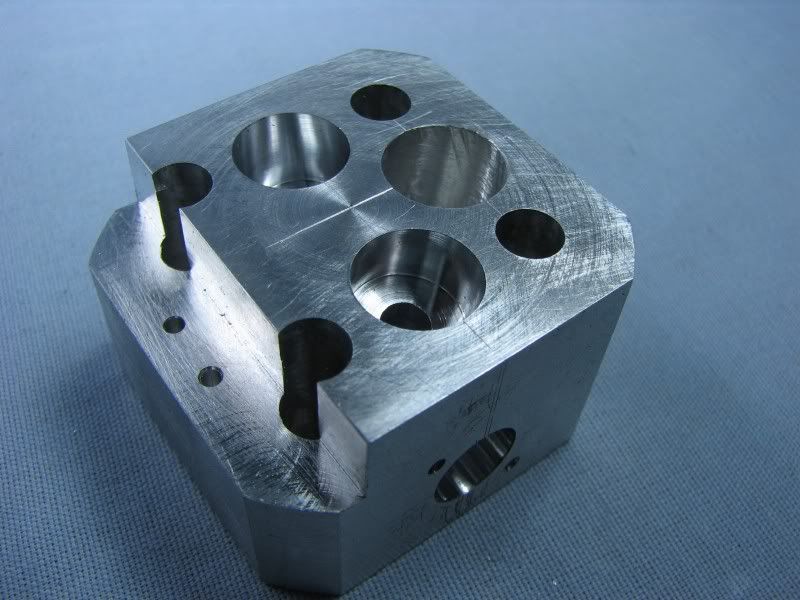
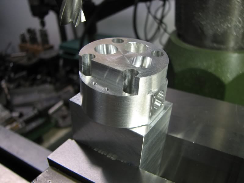
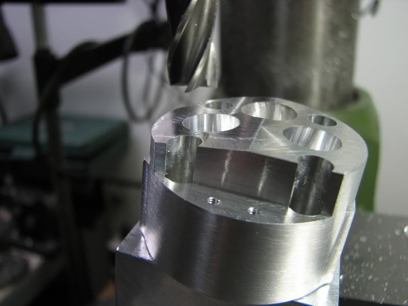
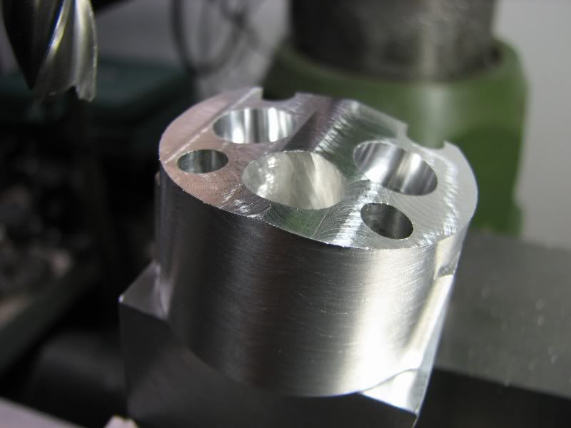
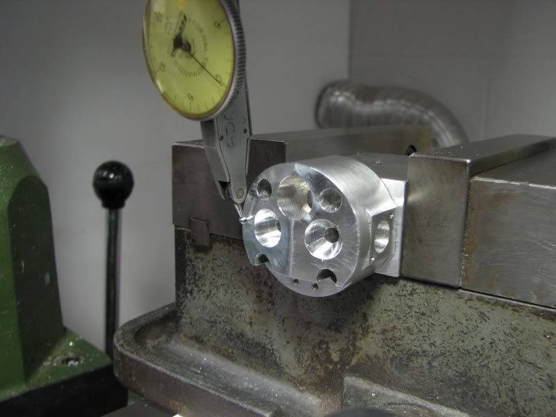
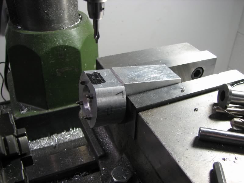
The fixture block that I made for doing most of the machining operations on the heads has become invaluable. Once I make a setup I can just rotate the head to the other port or whatever I'm cutting without having to pick up lines and centers again. Today I clamped the block in the vise and squared up the angled surface I put on the bottom surface that matched the angle of the valves and combustion chamber. With the head located on the dowel bushings as per the last operation I picked up my centers, set my digitals and started cutting. Basically it was a center drill, drill, undersized ball mill and finally the .375 ball mill to match the port coming from the combustion chamber. The final two pictures are a closeup of the combustion chamber showing the valve seat inserts and the other tries to show the exit of the port from the combustion chamber.
gbritnell
JN.jpg

JO.jpg

JP.jpg

JQ.jpg

JR.jpg

JS.jpg
JT.jpg


Thanks Mati, I won't say it's out of the question but for now there's enough work with the machining and documentation as it is. Once the engine is finished I could probably contact someone at those publications and see what they would like to do.
George
 

Yes, it would be a lot of work to put it all together, but much of it is done already. On the other hand, it is a hobby, and if one feels pressure to publish, then it's not a hobby any more. I'm author or coauthor of about 150 various publications in "real life" so I know the pain. But, there is a lot of satisfaction in doing so.

Looking forward to the next installment.

M.
 
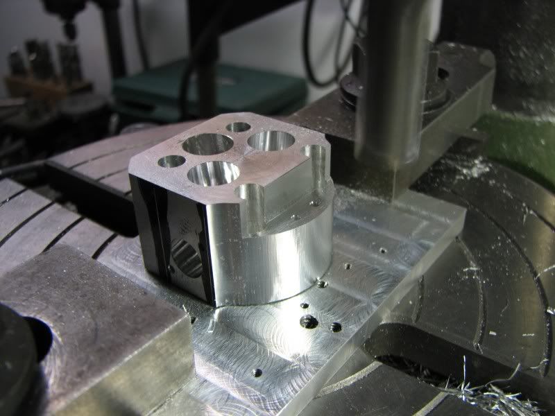
The next machining operation on the heads was to counterbore the valve guide pockets. I'm not posting any pictures of that step as it was just a matter of bolting the heads to my fixture bar, picking up center and with a flat bottomed .438 dia. endmill quilling down to the proper depth. The next step was to cut the relief on the cylinder side of the head. For that I would need another fixture plate which I also would need for machining the outside shape of the head. It is just a flat plate with a countersunk center hole and four tapped holes for the head bolts. With the plate finished I took the vise off of the table and mounted the rotary table. I put a rod with a chamfer on the end into the spindle and brought it down into my countersunk center hole to locate the plate while I was bolting it down. The plate was indicated parallel with the table so that I would have a reference point to rotate and cut the relief. The relief is .015 deep.
JX.jpg

JY.jpg


This photo shows the counterbores for the valve guide pockets and the step for the rocker post mounting.
JZ.jpg


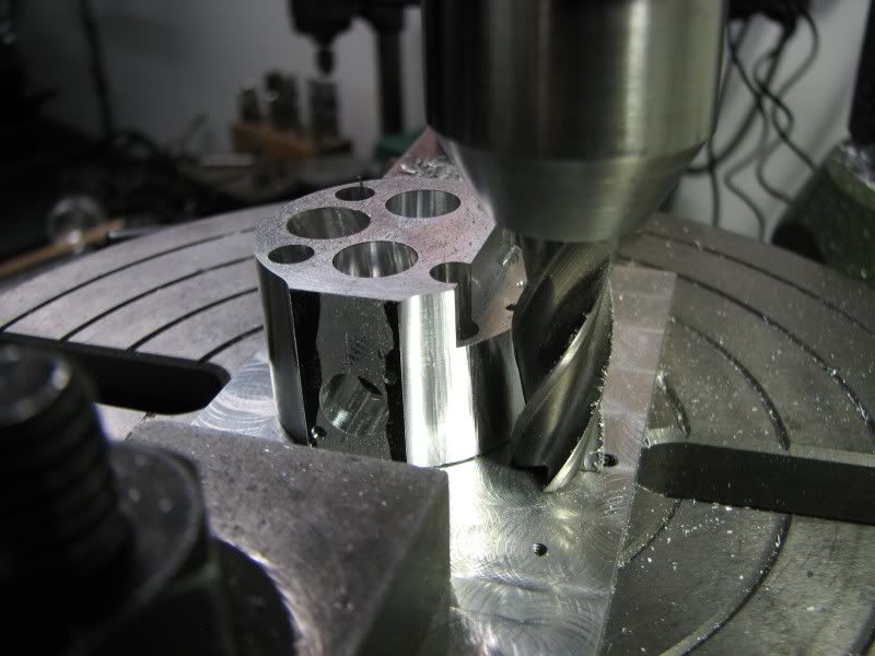
Now it was time to cut the radius on the outside of the heads. The reason it wasn't turned in the lathe is because there's a flat where the manifolds bolt to. I layed out the width of the flats, mounted the heads and spun the outside radius.
KA.jpg

KB.jpg


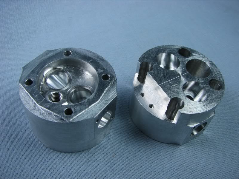
These two pictures show the heads to this point.
KB.jpg

KD.jpg
 
With the rotary table work complete, it came off and the vise went back up. The heads got mounted on my fixture bar and the top angle of the head was cut.
KE.jpg

KF.jpg

KG.jpg
 

Beautiful work George!

Its coming along great.
 
Now the operation that I have been worrying the most about, cutting the fins. In all my years of machining the one tool that I don't care for is the mill saw. At least this one is a relieved type and with using 7075 aluminum there shouldn't be a problem. LOL!
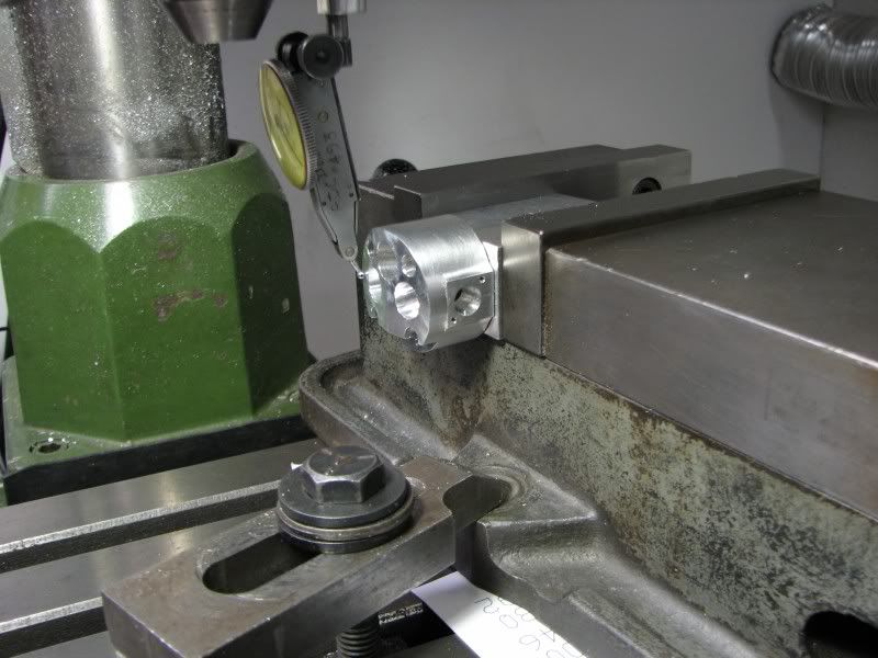
With the head bolted to the fixture bar I mounted it horizontally in the vise. I then took the one mounting bolt out of the vise and kicked it over the required angle. A quick check with the dial indicator and the fun is about to start.
KH.jpg

KJ.jpg


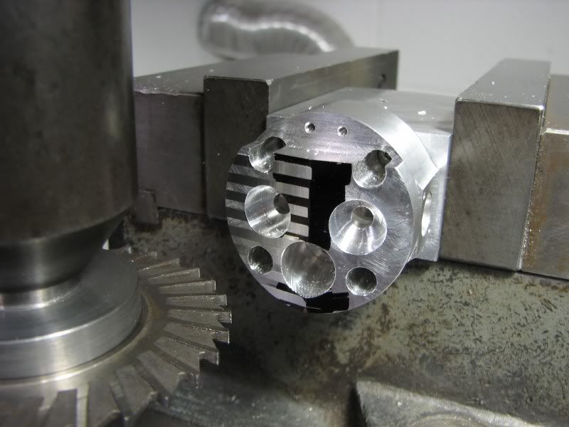
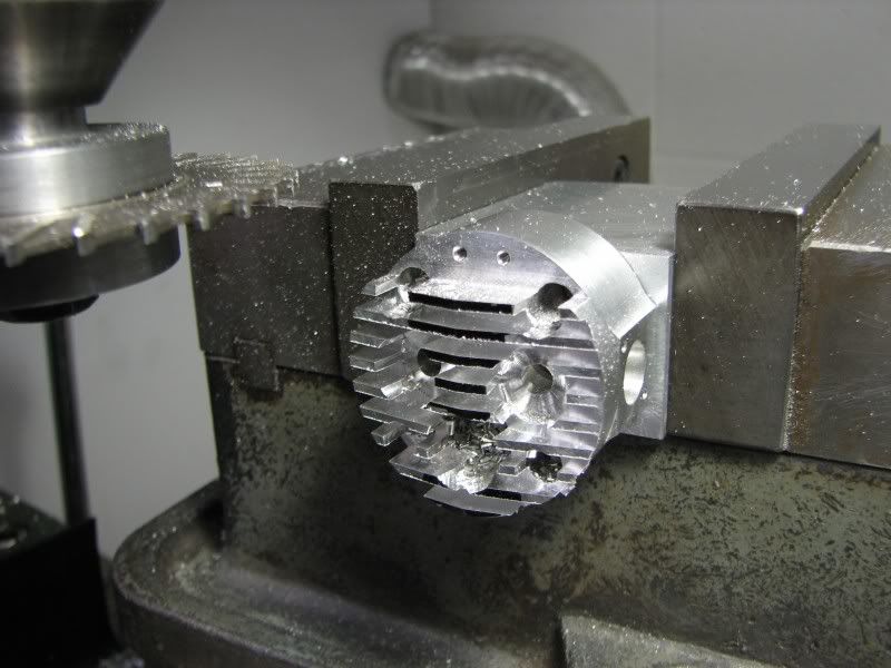
The wall where the lifter bracket bolts to is the outside of the one fin so that was my starting point. With an indicator in my surface gauge I picked up the top of the fin and then set the top edge of the flutes of the saw at this height. Each fin is .062 wide with .093 spacing between them. With my Z readout zeroed I moved down .062, lightly touched the head and cut a .003 witness. I wrote down all my steps on paper so I proceeded to cut witnesses across the head to make sure everything ended up where it was supposed to be. With using a saw you want to make sure you slow your rpm down, in this case the saw is about 4" so I was running at about 475 rpm and conventional cutting. Everything looked good so I went back to my starting number, went to depth, .230, and started cutting. No glitches!!!
KL.jpg

KM.jpg


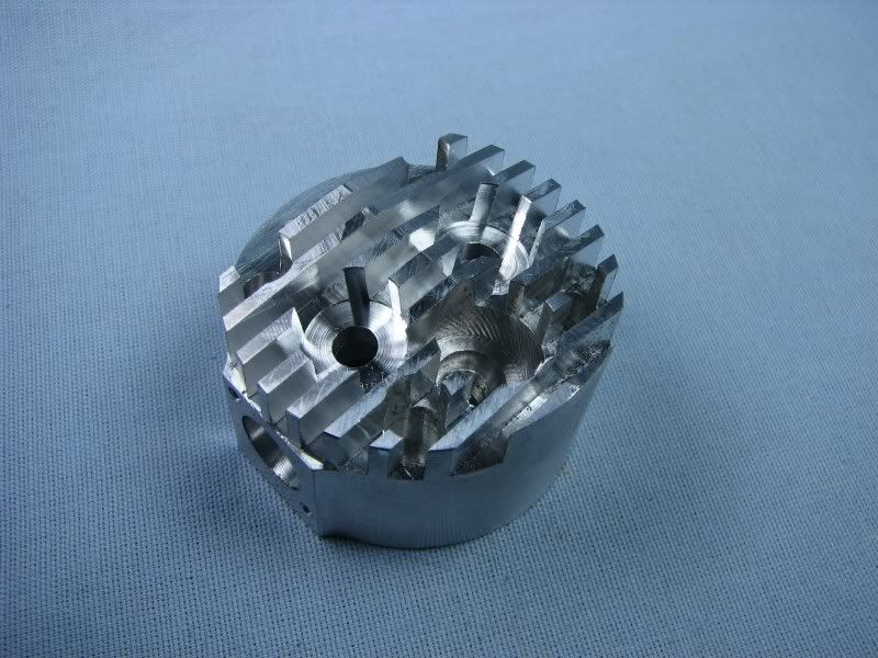
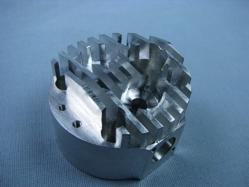
The last two shots show the competed fins, at least on the top. The corners will have to be radiused but that's all file work.
This thing is actually starting to look like an air cooled head!!
George
KN.jpg

KO.jpg


I should have mentioned that when I got finished cutting the one side of the fins at the set over angle of 8 degrees I was going to take this head off of the fixture bar and start on the other one. The more I thought about it the more I realized that if it didn't get bolted 'exactly' in the same spot my fins might have a mismatch so I loosened the vise, rotated it 8 degrees the other direction, touched the top of the head and finished cutting the fins without removing it. This turned out to be the way to go. After posting this part I'm headed back to the shop to finish the other head. Tomorrow will be the horizontal fins.
George
 
Hi George. Your project and progress is very impressing! :bow:
It might be hard for some to believe that complex parts like the ones in your posts can be made with a basic manual mill/drill. I saw it with my own eyes, and still find it hard to believe.

What they say is true, "It's the man, and not the machine." ;)

-MB


Nice work George.

Why use 7075 instead of 6061? Sorry if this has been covered before but I can get 6061 fairly easy but not 7075 unless I order it. I can get 6061 at the scrap yard. They get a lot of jig plate aluminum which I assume is 6061.

Ron
 
Hey G!

When you use a saw like that is it best to take one cut at full depth?

Seems that you should have the saw conventional cutting also. Is that what you did there?

I ask because i have cut with a saw twice now and both times looked like a$$%^&*!!

Thanks G!!

Steve
 
Nice work George!

I agree with the others on the workmanship, but the pace you are working is what really amazes me. If I were to try to keep up, I'd probably hurt myself!

BTW Ozzie, jig or tooling plate is probably not 6061. Most jig or tooling plate is rather gummy to machine, but some, as MIC-6 is cast. We have been getting tooling plate at work for some time now that is also cast, but not MIC-6 either.

Back to the WIP.

Kevin
 
Hi Ron, 7075 is a harder or should I say not as gummy as 6061. Don't get me wrong, I use plenty of 6061 it's just with having to cut the fins I didn't want the chips to bind up. It's kind of like comparing 1018 crs to 12L14. They're both steel but cut completely different.
Steve, with a big saw like this I always conventional cut. My machine is not that rigid and the head was being held by four 5-40 socket head screws. For smaller parts I will sometimes climb cut when sawing. It just depends on the width of the saw and the material I'm cutting.
Kevin, when you've been at it as long as I have you kind of know 4-5 steps ahead what you're going to do so it flows along quite well. You have to understand that I made the drawings so I've thought out most of the operations while I was making the drawings. I designed it with building it in mind.
George


Thanks for the info,Kevin.

George,I guess what I'm really asking is can you use 6061 instead of 7075 for IC engines? I have plans that call for 7075 but have 6061 on hand. If I have to get 7075 I need to started stock pilling it.

Ron
 
Hi Ron, sure you can use 6061. The only time I definitely use 7075 is if I'm going to make aluminum connecting rods. I just used it for the heads because of the deep fins.
George
 
Isn't it kind of funny how certain jobs get under a guys skin? George dosen't like using slitting saws. I think it's kind of fun. I don't mind taping small holes. But large ones I dislike to do? No reason really that I can think of either. I just don't like it much.

Ok, Back to the program. Nice job on those fins George!!! :bow:
 
The heads are looking great, George. I don't know what else to say. I think I've use up my lifetime's worth of superlatives in commenting on this mechanical work of art. If I could think up something new, I'd say it here!

Thanks again, for the photos and narrative.

Dean
 
Excellent job George ! :bow: :bow:

Regards, Arnold
 

Latest posts

Back
Top