3cc Diesel - My first ICE

Home Model Engine Machinist Forum

Help Support Home Model Engine Machinist Forum:

This site may earn a commission from merchant affiliate links, including eBay, Amazon, and others.
Bob, another plus side of the boat idea is weight... Not nearly as critical as being in an aircraft!

I think your engine will be light enough that an aircraft option is easily obtainable, but the Crusader I am building seems like it will be a bit on the heavy side for flight.
 
W/E,

If after all this mine don't run flight will not be a problem :p :p :p, just the sudden stop at the end of its ride ;D

Best Regards
Bob
 
Maryak said:
W/E,

If after all this mine don't run flight will not be a problem :p :p :p, just the sudden stop at the end of its ride ;D

Best Regards
Bob

1459.gif
516.gif
671.gif
Thanks for the chuckle!!
 
Maryak said:
Eric,

Thanks for your comments. The short answer is I don't know ??? ??? ???

My Grandson is almost 16 and I thought about a model aircraft that maybe we could build together. Ran it past his mum, (my one and only beautiful daughter, actually she looks very similar to Nicole Kidman). She nearly freaked and I got dressed down. The lad is Dyslexic and one of the problems is he has no concept of personal safety. A propeller at 5000rpm was definitely out.

Any suggestions would be very welcome.

Best Regards
Bob

You could go for a ducted fan - Hide the prop. Or even bypass the engine and use it for another project - and go for a glider / electric flight model (much less dangerous (It can hurt though, so it helps lessons to be learned without cutting fingers off !))


RC aircraft are so much fun it's a shame to miss out on them - AND building them can lead into othe hobbies such as engineering!!!!
 
Rick,

Thanks for your input and suggestion about gliders. :bow: At least I now have some very good pointers.

A little voice keeps saying "Finish the engine first....finish the eng...... finish the......." :p :p

Best Regards
Bob
 
EOW again :eek: :eek:

Managed to get a little done today and the head is looking like a head
wow.gif


The original plan called for the compression screw to be tapped directly into the head, also there was an option of a steel or aluminium head. As I opted for the alloy head I was not too happy about the compression screw being tapped directly into it.

Can't remember where I read it but the gist of the comment was, " And a very nice finishing touch was the insert in the head incorporating the compression screw."

Bearing this in mind and my own opinion that steel on aluminium was not the greatest, I settled on a brass insert, (coz when I looked, I had no bronze other than a big lump being saved for a bigger job ??? ???).

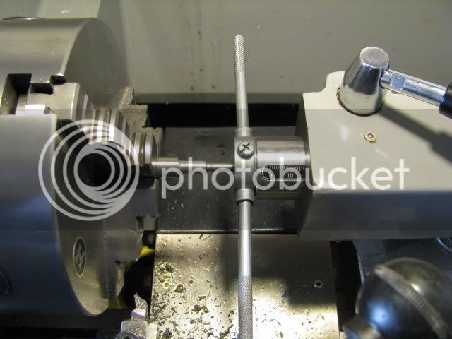
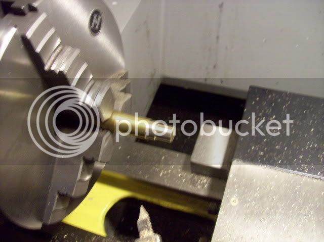
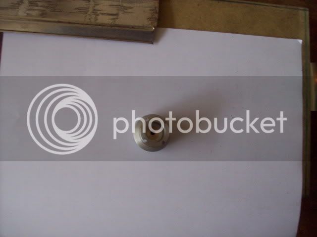
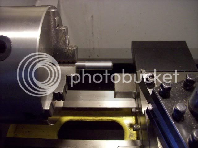
The sleeve blank ready for tapping and parting off.

100_0610.jpg


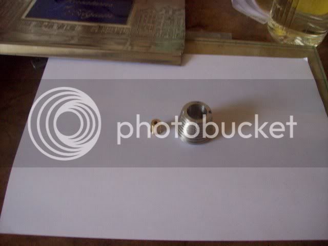
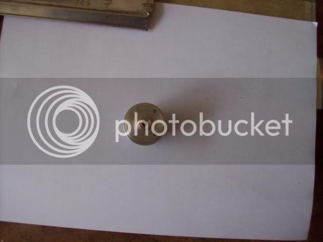
The head and tapped sleeve.

100_0611.jpg


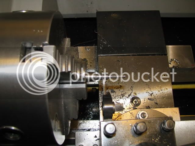
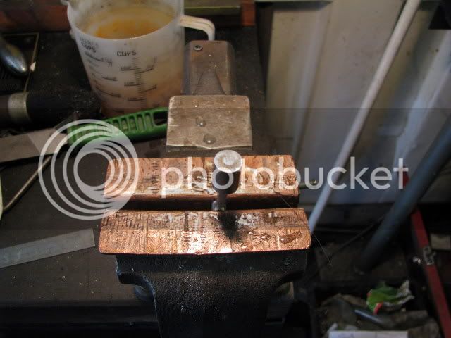
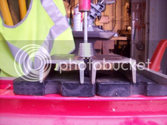
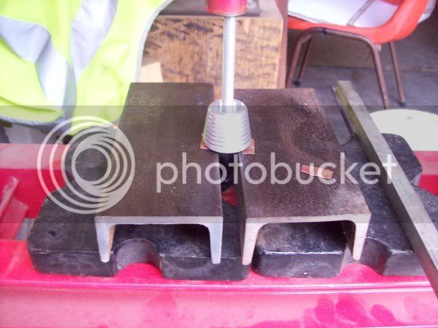
Pressing the sleeve into the head - note the locating screw on the underside to square things up before going under the press.

100_0612.jpg


100_0613.jpg


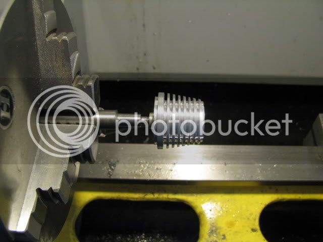
The sleeve in the head - The shoulder on the inside is insurance against things moving when it gets to operating temperature ::)

100_0614.jpg


I thought it would look snazzy if the sleeve was above the top of the head so made it 1/8" longer ;D

100_0615.jpg


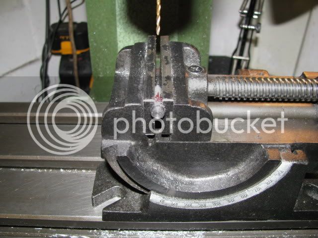
Some brightstock being turned into the compression screw.

100_0616.jpg


Have a good weekend
icon_super.gif


Looking good Bob. What is the function of the compression screw in your engine?

Cheers,
Phil
 
Phil,

Thanks for your remarks.

The cylinder in this design carries 2 pistons, a power piston which drives the crank and opposing it a contra piston which controls the compression ratio between about 16:1 to 20:1. The compression screw controls the position of this contra piston which is adjusted for power, even running etc. I have read and been told that this is necessary due to differing atmospheric conditions such as pressure temperature and humidity all of which have a bearing on how the engine performs on a given run. :eek: :eek:

In todays world apparently these engines are used primarily for control line racing of model aircraft and dog fighting, (how this is done with control lines is beyond me). I am advised that they have a much greater speed range than other types of model engines.

I have no experience with any type of model IC engine, so I am merely repeating parrot fashion what was read and said.
confused0024.gif


Best Regards
Bob
 
So the compression screw arrangement seems to serve the same function as found on some older style diesel engines. I have a clone of a Lister diesel engine (6 hp @ 600 rpm, 800+ lbs) and some of these have been produced with this system. Does that mean your engine will run on diesel fuel? If so, that would be extremely cool 8)

Cheers,
Phil
 
Phil,

Alas it is not a true diesel but a CI engine
icon_mecry.gif


The fuel is a mixture of Power Kero, or Jet A1, Ethyl Ether and Castor Oil. The local model aircraft guys have offered to help me set it up, mix the fuel etc and show me the correct way to start it without losing a finger
gasping1.gif


Reckon I will avail myself of their help. I only made 1 phone call and the secretary of the club was all about like a can of worms. Restores your faith in human nature :bow:

Best Regards
Bob
 
Ah, got it! Model airplane engine fuel. Will your engine have a glow plug or does the compression adjustment allow it to "diesel"?

Cheers,
Phil
 
Phil,

It, (I fervently hope ::)), will Diesel. There is no glow plug or other ignition than compression.

Best Regards
Bob
 
Hi Guys,

Bob..... excellent progress on your diesel, it is really beginning to look the part now.

I think you may find that your estimations of the RPM output may be somewhat low..... typically these engines were quite capable of more than 11,000 - 12,000 rpm. depending upon the propeller size used and the exact fuel mix.
The fuel used for racing (control line team racers) depended upon the CLASS of the races being flown (open class or FAI class (Federation Aeronautique International)).

FAI class was restricted to STRAIGHT fuel mix, as per your formula.

Open class more often than not had an additional ingredient (Amyl Nitrate) as an ignition booster...typically between 5% and 15%.

Control line combat also used this nitrated type of fuel.

Some of my own Racing diesels (Oliver tiger, ETA 15 etc) at 2.5cc were/are capable of turning an 8" dia x 7" pitch or a 7" dia x 9" pitch propeller at around 18,000 RPM.... and yes I started them by hand...starters were not allowed under the rules and in any event would have mangled the wooden racing props.

Phil..... The majority of Model Airplane Fuel, as you would now know it, would be for GLOWPLUG engines.

Very few diesel (CI) engines are manufactured nowadays (regretably), however, some model stores still stock the correct fuel for them.

GLOWPLUG engines use a fuel mix of 75% - 80% METHANOL (as used for drag racers) and 20% - 25% SYNTHETIC RACING oil. 
This would be a straight mix.

A racing mix would also contain between 5% - 15% NITRO METHANE as an ignition booster.

Model Diesel (CI) engines will not run on this type of fuel.

For either fuel type, when a nitro additive is used, the amount of oil is typically reduced to around 15% and the other ingredients adjusted to maintain the 100% total mix value.

WE....
Your Crusader 0.60 engine will use the METHANOL based fuel and just to give you an idea..... it would be quite capable of flying a 10lb - 12lb model aircraft, and at 80MPH or more.
It will probably turn a 12"dia x 6" pitch propeller at upwards of 12,000 rpm and with some NITRO METHANE in the mix could well get 14,000 rpm.....
It will probably deliver close on 0.8BHP or even more.

Modern 0.60 engines are capable of more than 1.2BHP.

Hope this will give some encouragement to have a go.

Best regards.

Sandy.

 
Sandy,

Thanks for your input and encouragement, plus all the information on model aircraft fuels :bow:

Best Regards
Bob
 
Mondayitis,
mgboxedin.gif


One of those days when your are flat out but achieving little forward motion.

That pretty well sums up today.
icon_treadmill.gif


On the plus side the new camera is a beauty and I hope you like the shots from it
Flahssssss.gif


Threading the compression screw.

IMG_0018.jpg


Testing the thread in the head.

IMG_0019.jpg


Parting off the compression screw.

IMG_0022.jpg


Cross drilling for the T handle.

IMG_0023.jpg


Poor mans T handle ::)

IMG_0024.jpg


The piston assembly complete and soft soldered together.

IMG_0025.jpg


Not much was it :mad: :mad: ??? ???
 
Maryak

That camera sure seems like it is doing a beautiful job of showing what beautiful job you are doing with the compression screw. Well done Bob. :bow:

Cheers

Don
 
Don,

Thanks for the kind words and your continued support and encouragement. :bow:

Yes, I'm really chuffed with the new camera thanks to Crewcab and Mklotz for their valuable advise on what to buy
happyhappy.gif


It really has to be a good camera for ME
calicon17.gif
to take shots of that quality.

Best Regards
Bob :) :)
 
Bob, as for progress, I think you have done great. The small stuff does take more time. At any rate, the little engine is coming together and it looks like you have 'er on the downhill side of things.

Looking good!!
 
W/E

Thanks yet again for your input and support.
awink.gif


I hope today will see the engine assembled
mgyes.gif


Next is to make a mod to my grinder base so that the jig is held firm relative to the wheel.

That way I hope to be able to make more accurate form tools for the venturi and the bell mouth on the carburettor
eek3.gif


Best Regards
Bob
 
Bob,
Your superior use of the "Emoticon" is equalled by your excellent machining and photos :big:. Keep 'em coming.

Cheers,
Phil


Latest posts

Back
Top