I appreciate the offers of a 3D printed fan, and if I was going to be the only guy that built this engine, I would definitely take you up on the offer. However, I sell these plans all over North America. I want to find a solution that I can buy, because then the folks who buy my engine plans can buy their fans from the same source.---Brian
You are using an out of date browser. It may not display this or other websites correctly.
You should upgrade or use an alternative browser.
You should upgrade or use an alternative browser.
1" Bore x 1" Stroke Vertical i.c. Engine
- Thread starter Brian Rupnow
- Start date

Help Support Home Model Engine Machinist Forum:
This site may earn a commission from merchant affiliate
links, including eBay, Amazon, and others.
I certainly understand, and I hope I didn't come across as pushing this - just trying to give back in thanks for all of the information I have gained here! I have used the GPL license for the OpenSCAD file, so you are free to include it with the plans. I think. Maybe I need to change it to LGPL? In any case, my intention is for it to be freely available to all and sundry.
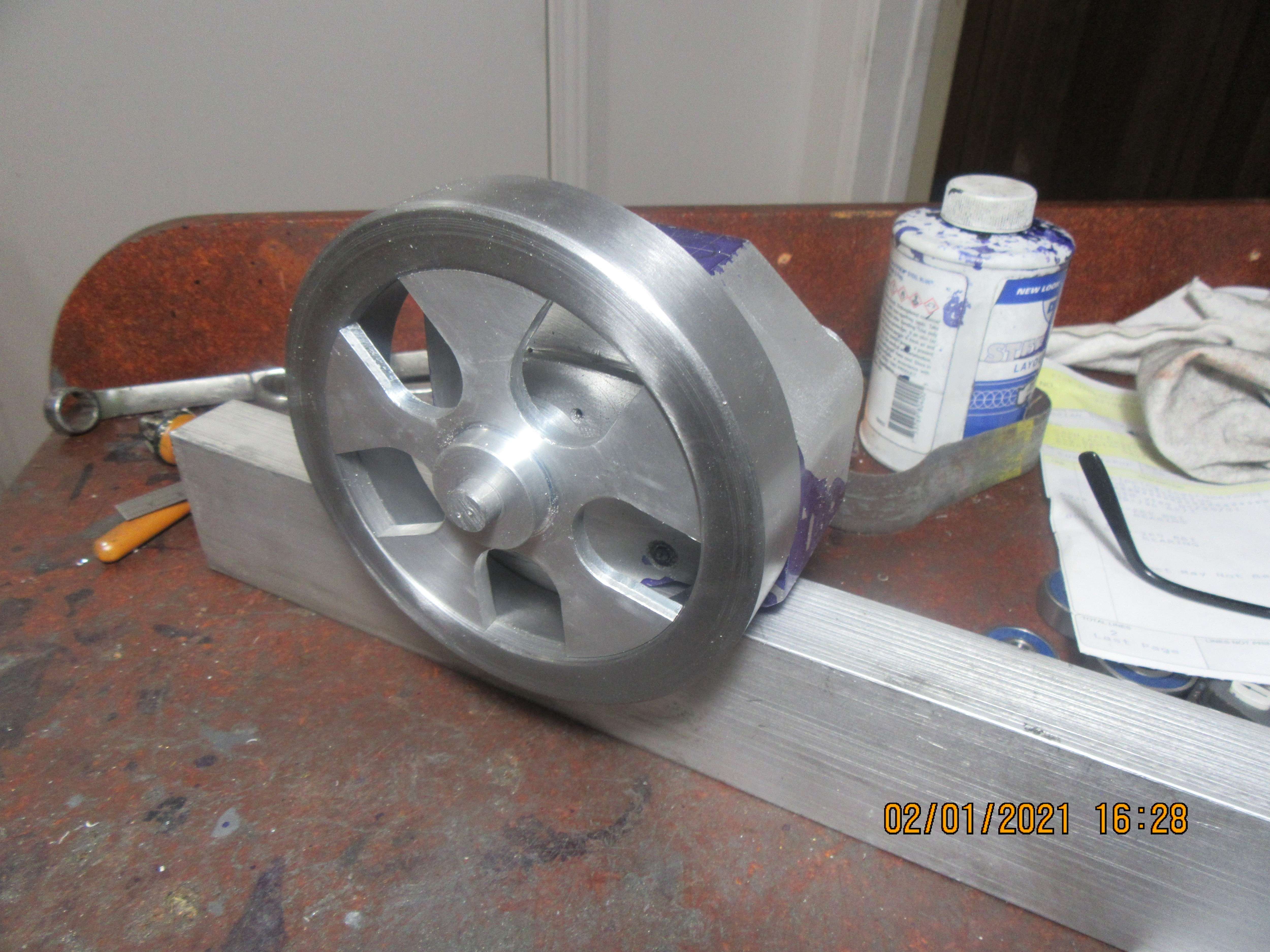
Okay---that's enough fun for one day. I kind of like the flywheel.

I think that went by too fast for me to follow, but that's a steel rim and an aluminum plate cut round to fit it? (Plus the cutouts) How's the plate held to the rim so that it won't slip?
Magic----
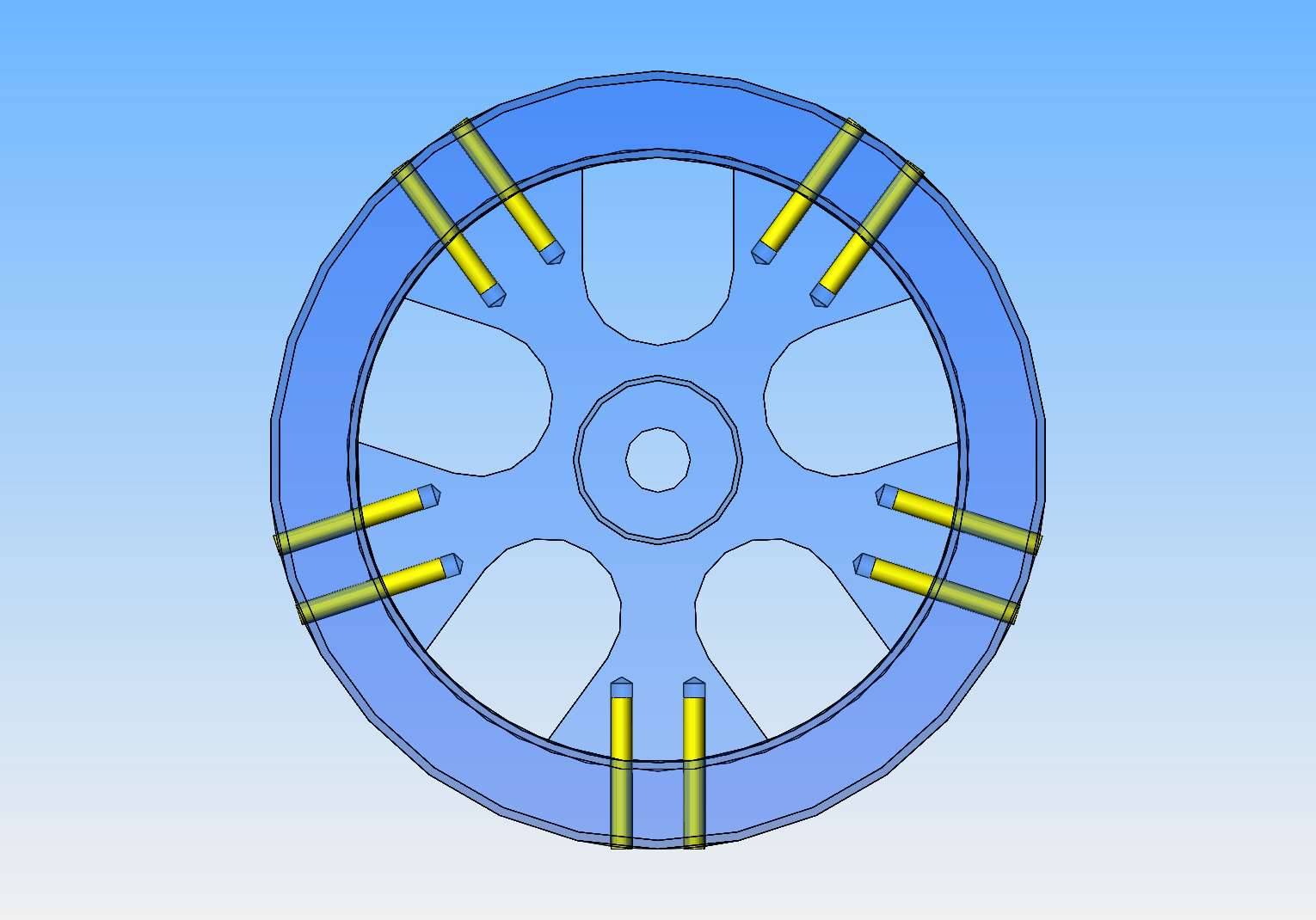
I'm sorry Bob---Not really magic. My plan is to drill 1/8" diameter holes around the outer ring and the inner web and Loctite 1/8" dowel pins into place on the center of the web, as shown. That may be subject to a bit of change, but not much. I don't really want to weld anything because of heat distortion, but I may make the 1/8" pins from brass and a bit longer than necessary and then turn the o.d. of the outer ring so that all that really can seen it two round brass dots at each web spoke.


$39.14
$49.99
Becker CAD 12 3D - professional CAD software for 2D + 3D design and modelling - for 3 PCs - 100% compatible with AutoCAD
momox Shop

$11.68
$14.99
Build Your Own Garage Manual: More Than 175 Plans: Step-By-Step Instructions (Creative Homeowner) Techniques, Tips, Diagrams, and More for DIY Building, plus a Catalog of Available Plans
Goodwill of Central & Coastal Virginia

$599.00
$649.00
FoxAlien Masuter Pro CNC Router Machine, Upgraded 3-Axis Engraving All-Metal Milling Machine for Wood Acrylic MDF Nylon Carving Cutting
FoxAlien Official

$19.15
$29.95
Competition Engine Building: Advanced Engine Design and Assembly Techniques (Pro Series)
MBC Inc.

$45.99
Sunnytech Mini Hot Air Stirling Engine Motor Model Educational Toy Kits Electricity HA001
stirlingtechonline
![DreamPlan Home Design and Landscaping Software Free for Windows [PC Download]](https://m.media-amazon.com/images/I/51kvZH2dVLL._SL500_.jpg)
$0.00
DreamPlan Home Design and Landscaping Software Free for Windows [PC Download]
Amazon.com Services LLC

$99.99
AHS Outdoor Wood Boiler Yearly Maintenance Kit with Water Treatment - ProTech 300 & Test Kit
Alternative Heating & Supplies

$26.89
$34.99
Peachtree Woodworking Supply Bowl Sander Tool Kit w/Dual Bearing Head & Hardwood Handle, 42 Pieces Wood Sander Set, 2 Hook & Loop Sanding Disc Sandpaper Assortment, 1/4 Mandrel Bowl Sander
Peachtree Woodworking Supply Inc
The round piece of aluminum was 3.50" in diameter. The inside of the heavy wall tube cleaned up at 3.428" diameter. I put in a 3.50 countebore for the aluminum web to set up against.
Thanks for the multiple clarifications. I guess the steel wall is about 1/2" thick for the entire rim? Interesting design! I'll keep watching.
Jasonb: I notice your Practical Mechanics picture show a bloke Graving. That's a skill I have not practiced in a decade or so - since I have had "better" cross-slide lathes. I wonder how many of the readers even know what Graving is? In my local club there is an "oldish chap who spent his working life as a hand-turner of wood. His "forte" was to make a hat - cowboy hat style with large brim - turned from a solid piece of wood - less than 1/8" thick. He the n softened the wood with steam and shaped it with the traditional vee in the middle, and curled brim. I have seen the photos of his display stand - they looked just like John Wayne could have worn! In his mid 70s he retired and sold all his wood-working stuff. Then decided with an empty workshop to try metal-work. He was interested when I explained how my Grandfather taught me Graving as a boy. So he decided to "give it a try" - as it was similar to his skill as a wood-turner. - He reckoned it was easier than working out "which way to wind the wheels on the cross-slides"! My Grandfather repaired clocks and made all the screws, etc. by Graving. Worked to Vernier 1/20th millimeter sizes. From memory, I think his collet chuck was for 1/4" max. The motor must have been smaller than the 90W motor on my Unimat... the whole lathe only as big as a computer key-board. Maybe I'll make myself a graving tool and give it a go sometime! I have used a tool held in Mole grips in the past, but a bit cumbersome. I used to make small screws for him - thread cut using what he called a die plate. Probably around 6 or 8 BA? - Nostaglia is not what it used to be.
K2
K2
Brian, I am interested in your flywheel design. I have a Brass ring (from a fire extinguisher?). Of course pinning is an obvious way to attach the rim to spokes. - But maybe I'll use some round bar spokes if I make a flywheel from my Brass ring? And I may silver solder the assembly... Then I'll have to decide what to make for the engine! I am fascinated by your work.... carry on.
K2
K2
I've done a bit of graving and tend to use my woodworking HSS scrapers which cut quite well on most metals, bar in the tool post makes a simple rest. Did you notice in the photo that the midget engine is driving the lathe via a line shaft on the bench
If you do go with a soldered up flywheel then solder in two stages with the spokes done on the first heat and then the hub on the second heat, that way you don't get distortion when the ring shrinks as it cools. One I did described here Preston's Oscillator
If you do go with a soldered up flywheel then solder in two stages with the spokes done on the first heat and then the hub on the second heat, that way you don't get distortion when the ring shrinks as it cools. One I did described here Preston's Oscillator
Thanks Jason - Good tips!
 K2
K2
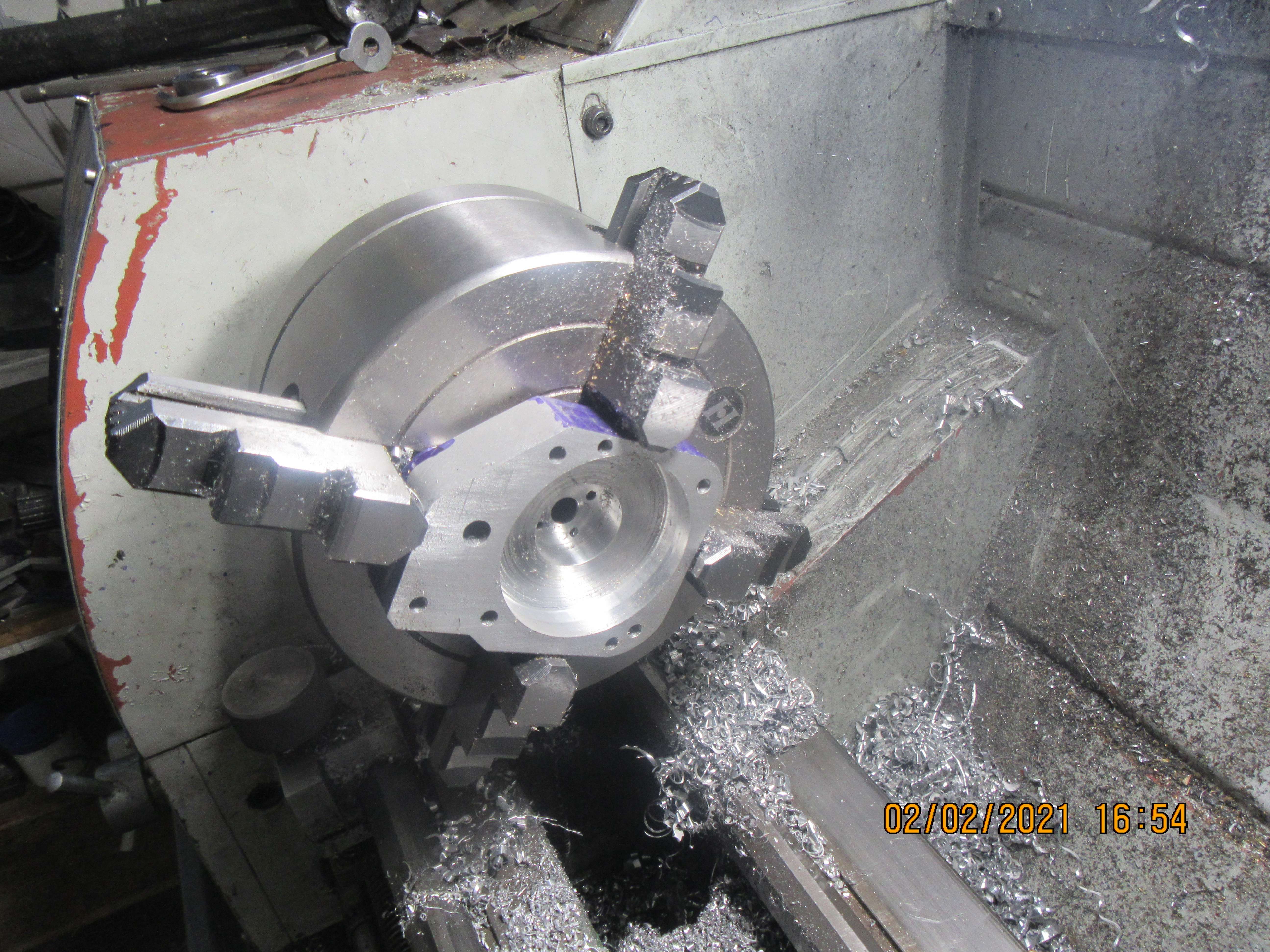
Today was the day to start counterboring the crank-cases. In this view, you can see that I have the counterbore for the 3/8" crankshaft bearing in place (It's a really deep one), and the large counterbore for the crankshaft, con-rod, and balance weights. There will be a second set-up in the 4 jaw to put in the counterbore for the camshaft bearings and cam. I would have been finished this side except that I had to take good wife down street to pick up a new microwave oven. In this horrible Covid winter, almost anything is a good reason to get out of the house.

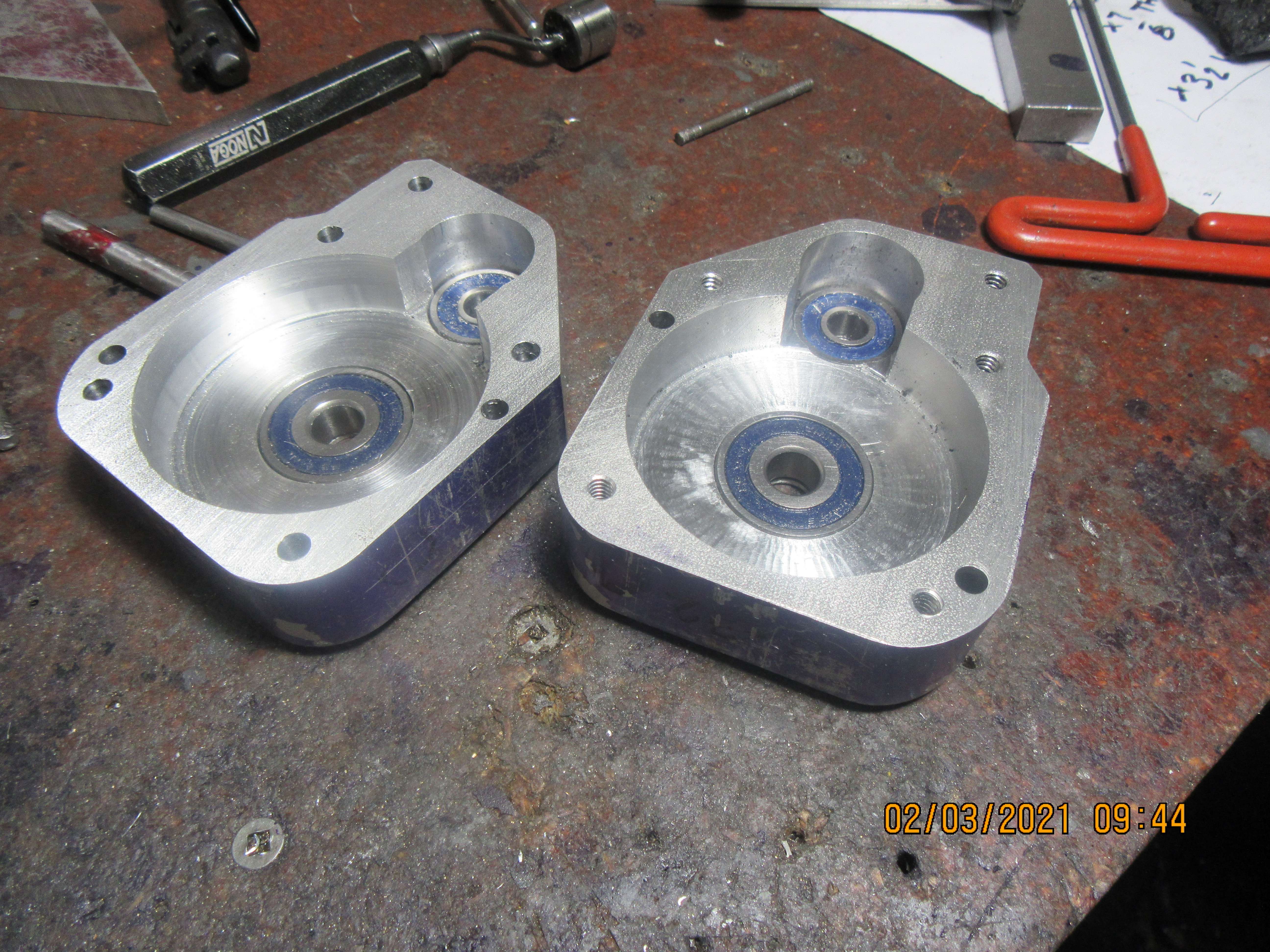
The internal cavities are finished in the crank cases. No real drama here. I set both crankcases up in the lathe to bore the large cavity and the bearing cavity in the center of the big cavity. Then I realized that I didn't need to do that for the third and final cavity --it was done on the milling machine. Very happy to announce that with the bearings in place and with shafts running through both bearings, the crankcases still mate up and the locating dowels still slide into place. Now I have to drill about 15 holes thru the crankcases and thread some of them.

I just found out that this engine will be painted. My quotes came in today----$55.37 for brass to make the gear cover. $12.03 for the same sized material in aluminum. $24.52 for enough brass to make the gas tank support in brass, and $4.97 for aluminum the same size. That is just outrageous. The "shine" on this engine will be shiny paint----Not Brass!!!----Brian
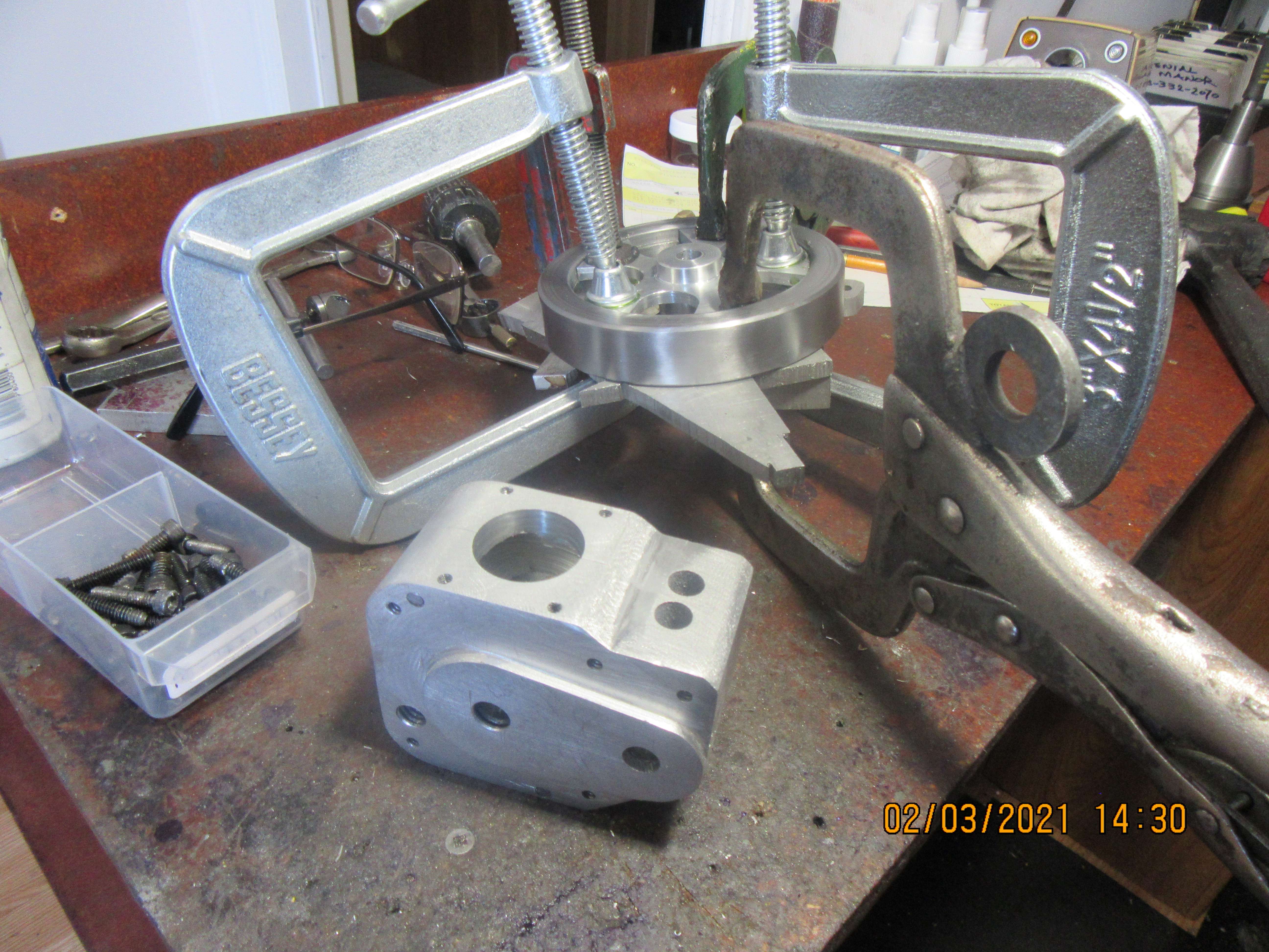
So there, (with a rather astonishing number of holes in it) sets the finished crank-case. Two holes have yet to be drilled and tapped for the gear-case, but I will wait until the gearcase is made before doing that. In the background you can see the flywheel with about a billion clamps on it. I was able to put a counterbore in one end of the outer rim, big enough to set the web up against. I Loctited it and put the clamps on. When the Loctite is totally set up, I will then do the drilling and pinning to hold the flywheel permanently together.

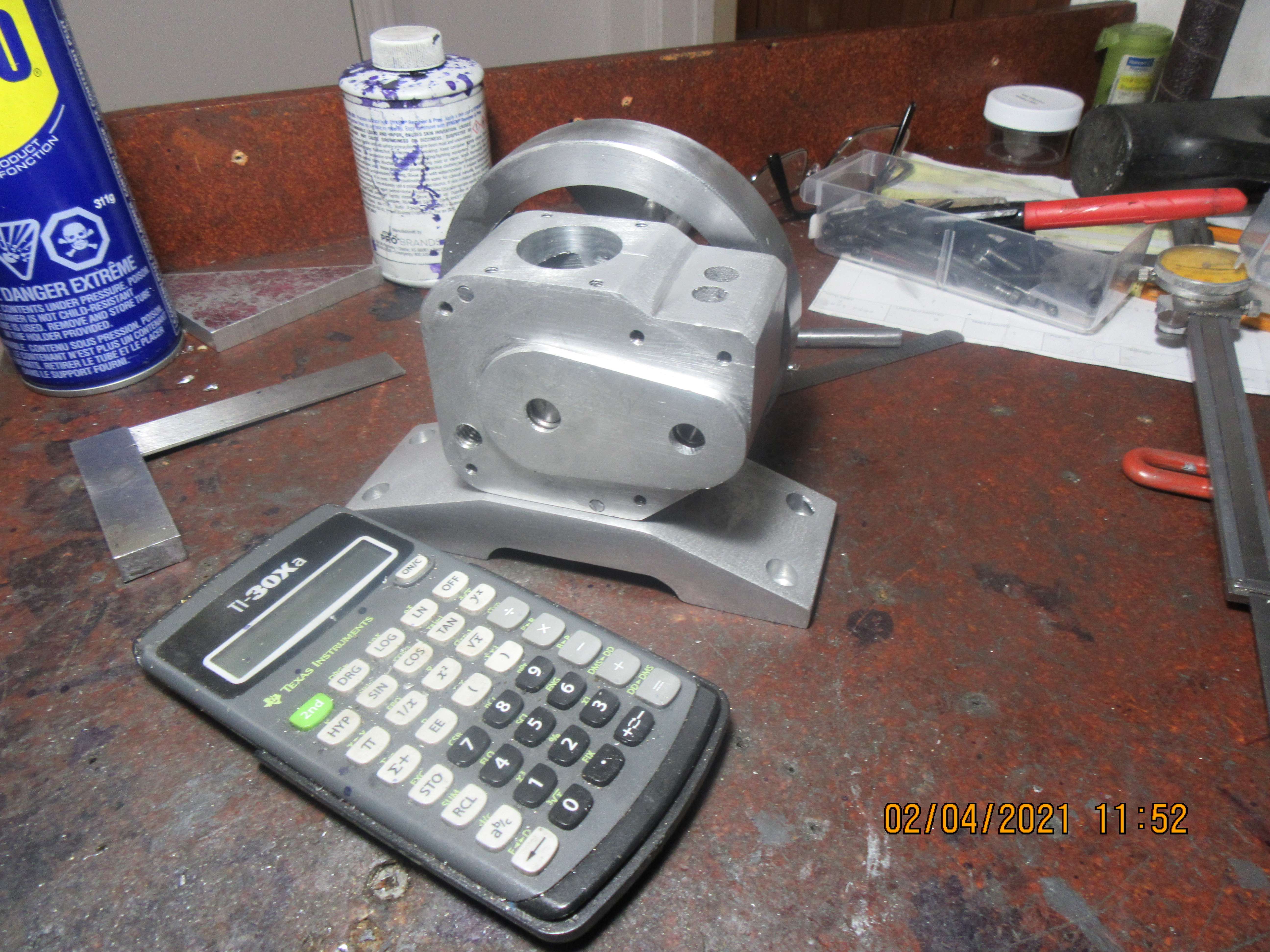
This morning I made the base. I have to pick up material downtown today, but it wasn't going to be ready until after lunch, so I put my waiting time to good use.

This is turning out to be a beautiful engine. Great work. And I too will probably take you up on the purchase of some plans. I've never built an IC engine. I've mostly got into this hobby through model steam engines on a lathe. But IC is definitely an area I would love to try! 
Looking forward to the next update!
Looking forward to the next update!
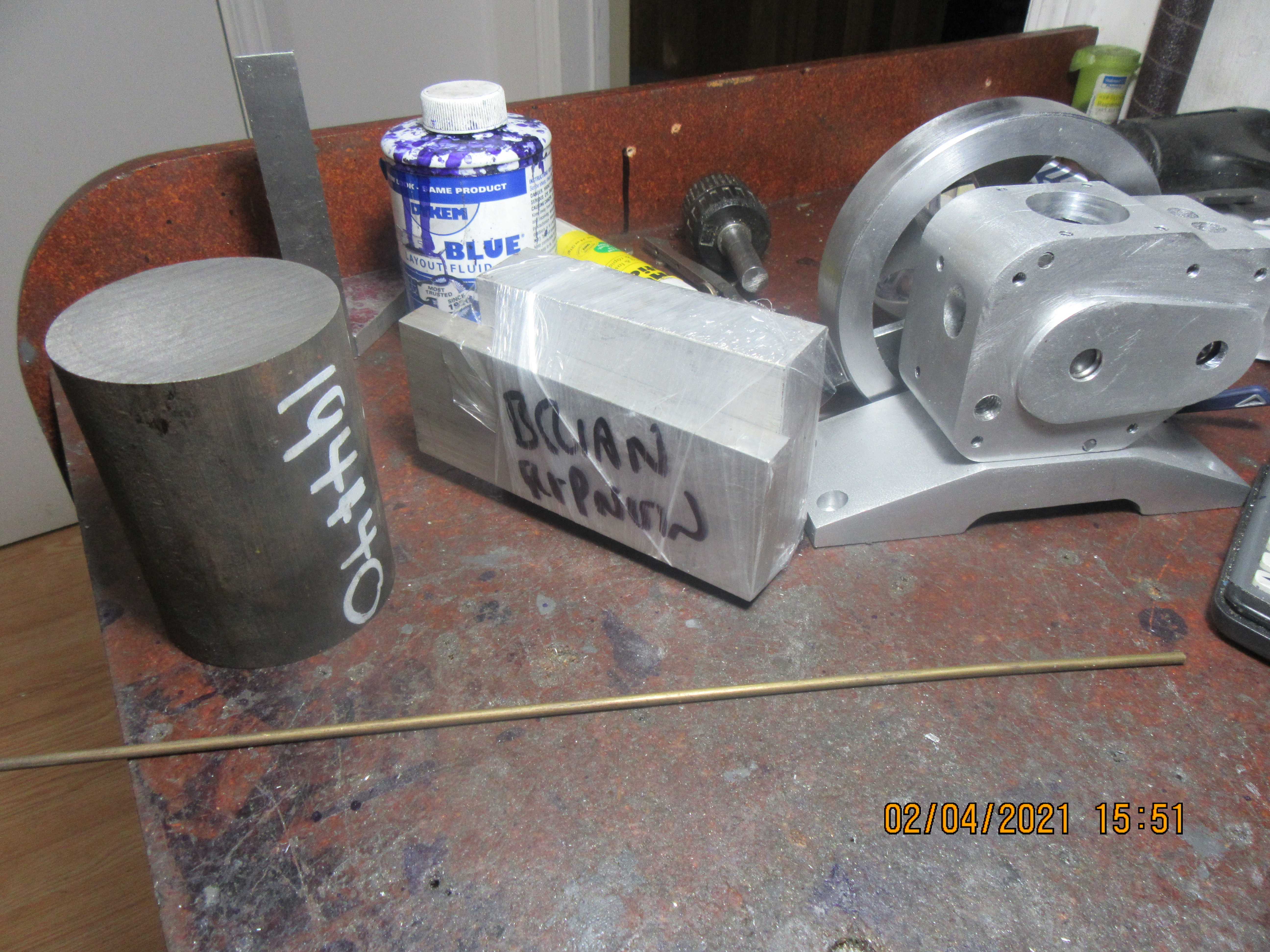
Home with more material. Grey cast iron for the cylinder and enough aluminum to make the outer gear case, the gas tank support, and a piece of 1/8" diameter brass rod to pin the flywheel with. That cost a grand total of $55.00. If you are an American looking at these prices I list for my builds, you can buy the same material for about 15 to 20% less, south of the Canadian border.

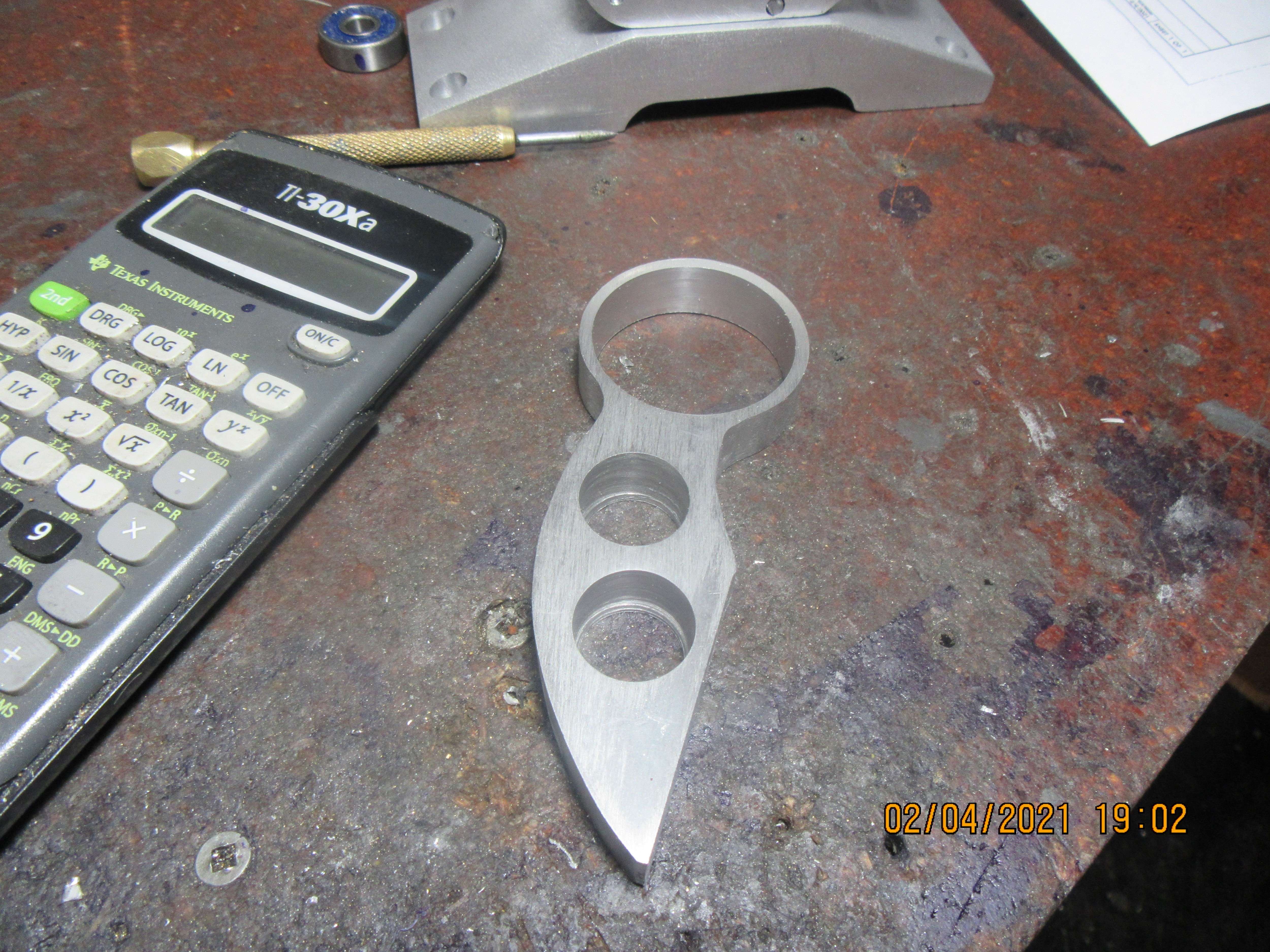
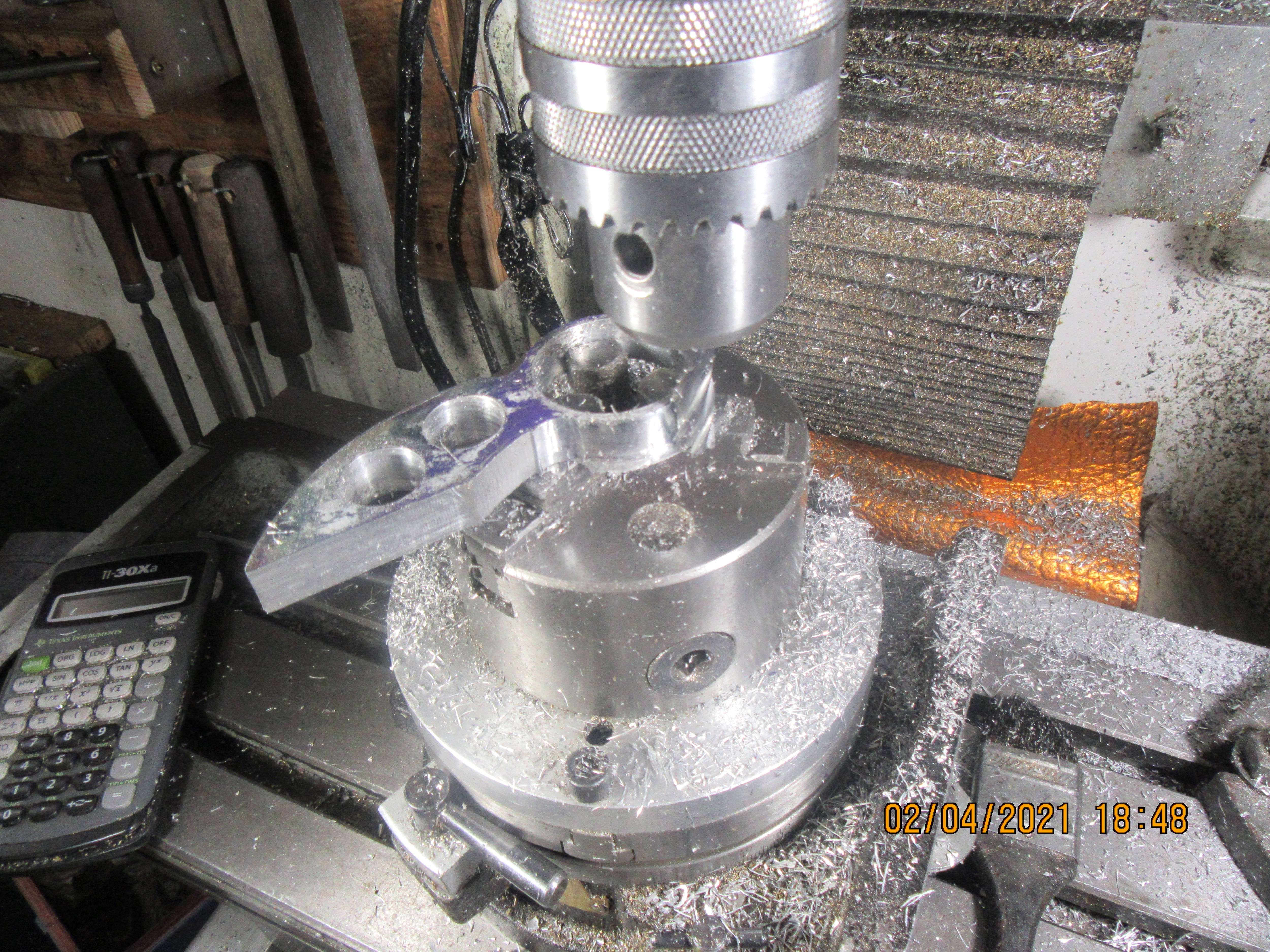
This gas tank support has more of an "artsy-fartsy" thing going on than the parts I usually make, but I like it. I think it adds a touch of beauty to an otherwise "plain Jane" engine. I have a bit more work to do on it, but I'll save that for tomorrow.


Similar threads
- Replies
- 11
- Views
- 1K
- Replies
- 1
- Views
- 200
- Replies
- 0
- Views
- 198


![MeshMagic 3D Free 3D Modeling Software [Download]](https://m.media-amazon.com/images/I/B1U+p8ewjGS._SL500_.png)


