Ball Hopper Monitor - Casting Project

Home Model Engine Machinist Forum

Help Support Home Model Engine Machinist Forum:

This site may earn a commission from merchant affiliate links, including eBay, Amazon, and others.
I think I am going to 3D print the parts for this engine, to give me a feel for the size of the parts, and to help me design and fit in the last bits and pieces.

I will include all of the bolt holes in all the parts, and make sure I don't have something like turned up a few days ago, ie: the spark plug going through the carburetor hole.

And I am out of time this year to progress on the design of this engine, so this will give me something to look at, and keep me thinking about this engine.

I feel like I don't really have a good enough understanding of the remaining parts to design them from photos, so this will allow me to fit the part to the print, such as the governor weight, rocker arm support, etc.

I will probably print along the parting lines, and check that while I am printing.

And a 3D print would make a nice table ornament too, but mainly it would give a good feel for the size of all the parts, and how they all fit together.

Edit:
One thing I have noticed from looking at the photos from various 4hp Monitors, there is generally some variation that can be spotted in each photo, and it makes me think the Monitor engines evolved a bit over time.

One photo shows a handle built into the flywheel, to start the engine; which was common on some of the old engines.

Other photos show variations in the governor weight, and the governor weight stop.

And there are some variations in the sides of the crankcase/cylinder, at the crankcase/cylinder junction, for rod clearance.

I have seen the Lone Star 2hp drawings, but they are for a 2hp engine, which is different from a 4hp in many respects.
The Lone Star kit did not rigidly adhere to the full sized 2hp desin in some ways, although I still consider it a stellar kit, especially with regards to the quality of the castings.

I find it best just to look at photos of full sized 4hp Monitors, and reverse engineer from those.
This method gives the most accurate representation, although it takes some time and effort to design this way.

.
 
Last edited:
I found a video that shows the trip mechanism for a 4hp full sized Ball Hopper Monitor, and I slowed it down to 10%.

This helps a lot in clarifying what is going on with the rocker arm, the governor weight mounted to the flywheel, and the "L-shaped" bracket that catches and holds up the end of the rocker arm.

Edit02:
After watching the video numerous times, I am going to re-write this description of what I think is happening below.


It has been difficult for me to get a good grasp of this mechanism and exactly how it catches and releases; when, and why.

.

Edit:
As I recall on my dad's 7hp Galloway, if you tightened the governor spring, the engine would run faster, so perhaps the same would be true for the Ball Hopper Monitor ? (ie: tightening the governor weight spring would decrease the number of revolutions between the engine firing).

Looking at the Galloway governor weights, and their connection to the sliding collar on the crankshaft, I can more easily understand how that engine is latching.

The Ball Hopper Monitor latch mechanism is not nearly as obvious as the Galloway to me.


.
 
Last edited:
Here is what I see happening on the Ball Hopper Monitor hit-and-miss mechanism.

There is a spring on the governor weight/arm that pulls it towards the flywheel hub.

The left end of the L-bracket rides on the green flange that is on the side of the governor weight.

As the engine rotates, assuming it is coasting down with the exhaust valve being held open, the cam rises every two flywheel revolutions and raises the end of the rocker arm.

When the end of the rocker arm is raised, the L-bracket is pulled to the right by the spring.
If the engine rpm gets low enough, the governor flange will be all the way down towards the center of the flywheel, the L-bracket will remain held to the right by the spring, and the rocker arm will move down with the cam, which closes the exhaust valve, and lets the intake/combustion/ignition/release sequence to happen.

Once the engine fires, the governor weight moves quickly outwards toward the flywheel rim, and its flange moves upwards/out from the flywheel center, the left end of the L-bracket moves upwards, which moves the detent to the left, and catches the end of the rocker arm, holding it up and holding the exhaust valve open until the slows down again enough to let the governor weight drop far to release the detent again.

It all happens so fast that it is tricky to understand when watching a full speed video.

.

xj1127.jpg
xj1128.jpg
 
Last edited:
Note that the mass of the governor weight/arm times the distance from its center of mass to the crankshaft centerline equals the mass of the flywheel recess above it times the distance from its center of mass to the crankshaft centerline.

.
 
This is the excellent video of a 4hp Ball hopper Monitor that I have been looking for.

You can slow this video down, and see the hit-and-miss mechanism pretty well.

High resolution video too (1080p).

 
Does not really need to be slowed down he has it running so slowly. Plug moved to the front too. Sproket suggests it may have run with a Mag at some time too.
 
The cam in that video I don't think should be striking the end of the L-bracket, as it appears to be doing.
I think that is a misalignment issue.

And the spring should be connected to pull the L-bracket back towards the engine frame.

Looks like he drilled a hole for the priming cup too.
The priming cup is normally where he has the sparkplug, and the sparkplug is normally on the left side of the valve chamber.

It is a very nice running engine for sure.
He has it dialed in well.
You can see/hear it draw open the intake valve, and then hear it fire near TDC, and then hear when the exhaust valve opens, and compare that with the flywheel position.

Very nice video, and very helpful.

.
 
Looking through an old Baker catalog, there are both wood and cast iron sub bases listed in the repair parts schedule.

I can't find any photos of a cast iron sub-base for a Ball Hopper Monitor, so we will have to improvise, and imagine what that looked like.

Perhaps the horizontal engine bases will give a clue as to what the Ball Hopper cast base looked like.

.
Edit:
I have a feeling the Ball Hopper cast sub-base was a crude representation of their wood base, with C-channel sections I would guess.

It appears that Baker created new engine designs, and then basically made minor changes to that design over the years.

Major design changes seem to have been saved for new engine models, such as the horizontal engines with their modern hemispherical combustion chambers and valve layout, and the "Little Pumpjack" engine, with its headless deisgn.

I have noticed that Honda tends to create motorcycle engine designs, and then use that same design for many years, sometimes in multiple motorcycle formats. It makes sense to put a lot of effort into getting an engine designed correctly in the initial design, so that changes do not have to be made during production.

There were a large number of engine manufacturers/engine designs in the early 1900's, and then a gradual consolidation into a few manufacturers with the more advanced higher rpm designs.

I suppose that is the natural progression with emerging technology such as gas engines.

Steam engines of the early 1900's were considered far superior to gasoline engines, as witnessed by the Mt. Washington Hill Climb by F.O. Stanley in 1899 in his Stanley Steam car; a feat that no gas engine of the time could even begin to approach.

Here is a link to the Mt. Washington climb:

https://stanleysteamers.com/centennial.htm
The success of the Stanley Steamer with the Mt. Washington climb was directly related to the output capacity of the burner, and the surface area of the tubes in the boiler, as well as the significantly higher than generally considered normal operating pressure of 600 psi.
The Stanley motor design would almost be an afterthought.
The original Stanley Steam auto used an engine designed by Mason, and the Stanley brothers redesigned and refined the Mason design, but the Stanley engine had its roots in the Mason engine, and used the same basic format/layout as the Mason engine.
As I recall, the D-valves in a Stanley engine experienced heavy wear since they were unbalanced.
I have seen folks who still run Stanley's convert the cylinder to a piston-valve design, which eliminates the high-wear problem with higher steam pressure.

.
 
Last edited:
After much consideration, I am going to make drawings and patterns for two scales of the Baker Ball Hopper Monitor.

I have decided to make a 1-off model at 1/2 scale, which will give 14" diameter flywheels, and an overall engine height of about 30 inches from the bottom of the flywheels to the top of the hopper cover.
These patterns will be 3D printed with single shrinkage factor, and smoothed, but kept in plastic form.

The second set of drawings and patterns will be for an engine with 10" flywheels, and I will use double shrinkage on these 3D printed patterns, and make permanent aluminum patterns.

I checked with Barney Kedrowski (the guy who provided me with photos of his 4hp Ball Hopper Monitor, which made this design possible), to get a second opinion, and he said "Go for it ! ".

So onwards we go with a 1/2 scale 4hp Ball Hopper Monitor.

I will have to get creative with the pours, and may have to use two furnaces (I have two), and do a double simutaneous pour on the larger parts.

.
 
Last edited:
Its too cold to do any foundry work (as if I had the time anyway), and so I will blog along with parting lines.

These are the parting lines that I know have to occur.

I see one overhang on the boss inside of the water hopper, and that could be fixed by filling behind the bosses away from the direction of pull.

I need to clean up the inside of the frame/cylinder, and get that smoothed out.

I do have a limited quantity of nickle-mag, or so I am told that is what I have.
I have not used it, but could use it to make the crankshaft in ductile iron.
Once it is gone, I don't have any more.
Someone sent me a small quantity of nickle-mag, but no supplier for restock.

The cylinder head does not have any draft on the sides, but I am going to try to pull it without draft angle, and I think I can get away with it on a part that is not too deep.

It should be noted that none of these pattern halves include machining allowances yet.

Normally bolt holes and keyways are drilled/cut after the casting work is complete.

As I recall, the valve chamber is not symmetrical about the parting line; it projects further in one direction than the other, which is no problem.

The muffler halves don't need a parting line.


.
CRANKSHAFT-PARTING-LINE-02.jpg
CRANKSHAFT-PARTING-LINE-01.jpg
CYLINDER-HEAD-PARTING-LINE-02.jpg
CYLINDER-HEAD-PARTING-LINE-01.jpg
FLYWHEEL-PARTING-LINE-02.jpg
FLYWHEEL-PARTING-LINE-01.jpg
VALVE-CHAMBER-PARTING-LINE-04.jpg
VALVE-CHAMBER-PARTING-LINE-03.jpg
VALVE-CHAMBER-PARTING-LINE-02.jpg
VALVE-CHAMBER-PARTING-LINE-01.jpg
PISTON-PARTING-LINE-02.jpg
PISTON-OUTSIDE-PARTING-LINE-01.jpg
MUFFLER-OUTTER-PARTING-LINE-01.jpg
MUFFLER-INNER-PARTING-LINE-01.jpg
FUEL-TANK-PARTING-LINE-02.jpg
FUEL-TANK-PARTING-LINE-01.jpg
CRANKCASE-PARTING-LINE-02.jpg
CRANKCASE-PARTING-LINE-01.jpg
HOPPER-PARTING-LINE-01.jpg
 
Last edited:
Many have contributed material to this project, and much of its success will be based on getting that information from several sources.
A guy on ytube named Barney took measurements of his 4hp engine, and sent me photos, and JasonB connected me with a goldmine of information of fb.
Despite my intense dislike for fb, this was a goldmine of info by any measure, and has helped round out some of the finer details of this design.

I really have much time to work on this design, but I don't want to see this rare opportunity wasted.
If I don't work on it, this project will go cold, and I will forget where I left it.

My 3D machine had to be moved, and so I am setting it up again tonight, so I can get back to business.

This week's focus is on creating 3D printed patterns for the water hopper.
I toyed with the idea of using the pattern halves as both as patterns and also as coreboxes, but I have decided that since I can 3D print everything, I may as well make separate coreboxes.

I have also contemplated making permanent patterns in 356 aluminum, and also permanent coreboxes in 356 aluminum, and after much consideration, I think I will make the water hopper patterns and coreboxes in 356 aluminum.
If the permanent aluminum pattern thing does not go well, I can bail out and just use 3D printed patterns.
The thing is, the 3D printed patterns will need smoothing work, and so if I go to the trouble of smothing out the 3D prints, then I will want those to last a long time.

Barney also wants a set of castings for his efforts, so I will try to do that for him.

Below is one half of the 3D water hopper model.
I need to add some filler behind the bosses, and add coreprints on either end.
The mirrored side of this hopper is more complex, and has a square side were the hopper bolts to the cylinder, so that will make the coreprint a bit more complex.
I suppose the coreprint can be round, even though the hole in the casting will have a flat side.

The plan is to cast these pattern halves inside my office, using my neighbor's kiln.
Hopefully I won't burn the house down, but if you happen to see a plume of smoke in the far distance, you will know what happened.

I need to check the mass of the pattern halves in solidworks, and record that, so I will know which crucible size to use.
The crucible number if approximately the capacity in aluminum in pounds; ie: an A10 will hold approximately 10 pounds of aluminum.

So many irons in the fire; so little time, but here we go.
Double-shrinkage, and damn the torpedoes.
.
 

Attachments

  • 107110-HOPPER-PARTING-LINE-01.jpg
    107110-HOPPER-PARTING-LINE-01.jpg
    49 KB
  • rIMG_3270.jpg
    rIMG_3270.jpg
    155.8 KB
  • rIMG_3271.jpg
    rIMG_3271.jpg
    133.6 KB
  • rImg_8418.jpg
    rImg_8418.jpg
    79.7 KB
  • rImg_8566.jpg
    rImg_8566.jpg
    100.5 KB
Last edited:
Once you get a certain amount of curves involved in a Solidworks 3D object, the program begins to stage a revolt.
At some point one has to resort to touching up the 3D printed pattern to fill in the final fillets and things that Solidworks refused to do.
Not a big problem; most of the pattern shape is there in the 3D print.
Added some holes for registration pins.
Added the coreprints top and bottom.
The coreprints are short due to me using bound sand.
They could be extended if greensand is used.

I will try 3D printing this half first, since it will be the most difficult, and may need some supports.
.
 

Attachments

  • Image52.jpg
    Image52.jpg
    257.9 KB
  • Image53.jpg
    Image53.jpg
    250.9 KB
Pulled the pattern half into the latest Prusa slicer.
The pattern was upsidedown, but easy enough to flip.
Units in inches.
Added double shrinkage.
Turned on supports.
Generated a G-code file.
I did not attempt to adjust the layer height, since the print time is already pretty long.

Time to see if the Prusa XL will fire up and do its thing.
I think the diameter of this pattern half is about 8 inches.
.
 

Attachments

  • Image1A.jpg
    Image1A.jpg
    785.3 KB
  • Image3A.jpg
    Image3A.jpg
    730.1 KB
  • Image4A.jpg
    Image4A.jpg
    834.8 KB
  • Image7A.jpg
    Image7A.jpg
    1 MB
Print attempt #1: Strike 1
3D model was still sized for a 12 inch flywheel.
Scaled 3D model up by 14/12, and resliced.

Print attempt #2: Underway

19 hour print time: grab lots of popcorn and tune in tomorrow.
Scale looks correct this time.
.
r_235520.jpg

Somehow the coreprint has vanished from the bottom, but I will keep printing.
I can print that separately and glue it in place.
r_000246.jpg

I selected "supports for enforcers only", whatever that means.
I don't see any supports getting printed, so that could be a bit of a problem for the flat window area.
I am not sure if I should have manually added supports, or selected "supports everywhere" ?
This first pattern print is going to be a learning effort, I can just tell.
Perhaps we can salvage it.
Using 15% infill to save a bit of time.

r001445.jpg

The wall thickness looks too thin, so I will correct that when I make the corebox.
I think the minimum wall thickness will have to be about 1/4 inch, just to have a chance at getting a complete mold fill.
I can perhaps add clay to the inside of this print to thicken the wall, since this will be a cast pattern.
The inside of this cast pattern is not critical; it just has to have a thick enough wall to fill.
The core will define the actual interior size.

The line coarseness does not feel too bad so far on the vertical surfaces, so we shall see what happens when we get into the curved surfaces.
The game plan is to use the fine sanding sponge in the variable speed angle drill to smooth out the print.
The smoothing is actually a small scale melting process, and produces no dust or debris, since it is melting the tops of the ridges, and moving that material over into the valleys. It takes just the right speed to avoid burning and smearing the exterior of the pattern.
I tried this on JasonB's flywheel, and the sanding sponge does work very well, and is a relatively quick and clean process.

This is the scaled up piece on the slicer bed.

Image1B.jpg


The bed on the XL gets quite hot, and remains hot for the entire print.

,
 
Last edited:
As you have features on the core that need to be correctly orientated it should not be "I suppose the coreprint can be round" as you need a good reference so that the core is placed correctly and a round print will not allow that.

You have some areas with no thickness/overlap so the print will fall apart probably before you even get to trying to pull it out the sand.

overlap.JPG


Also so of this fine detail even with bonded sand is going to be hard to stop the edges crumbling particularly as you have no way to easily get in there and remove layers which will tend to key the pattern to the sand,

weak.JPG


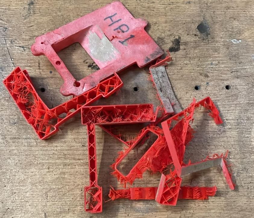
Outer wall thickness of the print and percentage fill seem too little. Have found that you need a good wall thickness at at least 50% fill if the pattern is to survive even the first moulding. The bound sands grip the pattern and it delaminates when you pull it out the sand. You may save a bit of actual print time but that is nothing compared to the time you will put into preparing the pattern only to have it fail and need reprinting. Put the time in now as you can be doing something else while it is printing, you can't get back the other wasted time. This is what can happen when you just use the default settings

d811dc23-9277-468b-95b6-13f86a813251.jpg


Also did you consider using variable layer heights, it will reduce the time needed to physically smooth the surface, again printing time does not cost you any real time but the smoothing does. Have you worked out how you will smoothe the areas that the power sander can't get to yet?

Is there a machining allowance on the bottom face?
 
As you have features on the core that need to be correctly orientated it should not be "I suppose the coreprint can be round" as you need a good reference so that the core is placed correctly and a round print will not allow that.
I am not following that train of thought.
I have used round cores and coreprints a lot.
The work perfectly.
One one side, the coreprint will be flat, to match the opening in the bottom of the casting.

You have some areas with no thickness/overlap so the print will fall apart probably before you even get to trying to pull it out the sand.
I noted that Solidworks was acting up, and so I will add some bondo on the inside at the thin spot to reinforce it.

I am surprised that you had that pattern fail.
Was it deep?

And as I mentioned, the interior of the 3D printed pattern will be filled out with filler prior to it being cast in aluminum.
But note that the interior shape will be determined by the corebox, not the pattern I show above.
The pattern half shown above only creates the outside shape of the mold cavity.
The core determines the interior shape of the casting.

The pattern half above only needs to be pulled once, since it will be cast in aluminum.
Even if the pattern fails, the bound sand mold will still be usable, and I have run across this before, once when I forgot to pull a 3D printed pattern during the strip time of the bound sand.

I think this method is going to work.
I will probably fill the interior of the 3D printed pattern a bit with clay, just to thicken up the aluminum pattern casting for strength.

Place your bets now folks; will the 3D print be usable to create an aluminum permanent pattern half ?
Or will it be a crash and burn situation ?
I have done a lot with 3D printed patterns and bound sand, and I understand the process well, so my money is on "It will work".

.
 
This is an original Cretors bearing support, I think this is for a No.01 engine.
Note that the interior has been cored out to allow for babbitt to be poured into this support.

rImg_5688.jpg

These are castings that Bob Pearson had made on bronze I think.
Note that Bob did not get the foundry to use the corebox to make the core.
If the corebox had been used, it would have had a round coreprint on one side, and a semi-circle with two flats on the other side.
The non-symmetrical coreprints are to ensure that the core aligns correctly, since the bearing top is sloped.
It is normal to have odd shaped coreprints that are not the same.
The only requirement is that you must be able to pull the core from the corebox.

s-l1600 (3).jpg
 
The parts such as the bead can be manually sanded, just as you would do with a wood pattern, but it takes a bit longer than sanding wood (maybe).
We have practices some techinques on filling and sanding the test dog print, and also on ceramic sponge sanding JasonB's big flywheel, so I think we have learned a lot in the process.

The sanding sponge works infinitely better than trying to fill a 3D printed pattern.
.
Here is the filled test 3D dog print.
This did not go well.
The filler did not really flow as well as I needed it to flow.
 

Attachments

  • r20230602_215007.jpg
    r20230602_215007.jpg
    242 KB
  • R20230607_012544.jpg
    R20230607_012544.jpg
    125 KB
  • R20230607_012734.jpg
    R20230607_012734.jpg
    154.7 KB
  • R20230607_013306.jpg
    R20230607_013306.jpg
    185.1 KB
  • R20230607_014445.jpg
    R20230607_014445.jpg
    182.6 KB

Latest posts

Back
Top