Vertical I.C. Rupnow Engine

Home Model Engine Machinist Forum

Help Support Home Model Engine Machinist Forum:

This site may earn a commission from merchant affiliate links, including eBay, Amazon, and others.
Here's a cheaper set Herbie - looks to be exactly what I've got (which work fine)but in a more colourful box. Still pricey but better than what you've found http://www.machineryhouse.com.au/M3381.

Edit to add - I see they don't have a shop in S.A. but pretty sure they do shipping. If not I could always pick up a set locally and post them to you.
 
Herbie--the only thing that I might add in relation to counterbores, is to try and find them with .010" to .020" clearance. That number refers to the size of hole you have drilled for the capscrew. On small capscrews you very seldom drill the clearance hole greater than .010" to .015" larger than the bolt. Then if you have a counterbore tool that is sold as "1/32" clearance, the pilot won't fit into the bolt hole.---Brian
 
I have a set of counterbores on my wish list as well. My current solution is to use a center cutting endmill to counterbore the holes as needed using a straight plunge cut after drilling the clearance hole for the screw. So far it has worked well, though one gets a ton of birds nests of aluminum shavings. The bigger counterbore on that cylinder support piece I had to stop and clear the birds nest about 3 times :-( But at least it gave me a flat bottom on the hole.

I can usually get <$100 purchases past my wife without her really noticing. But once it gets up towards $200 I have to start treading really lightly because it can get real messy really fast and she has one heck of a memory for said purchases.

Sincerely
Mark R. Jonkman
 
Heads up builders---The two cylinder head bolts that fit into the holes on the sloping side of the head--make sure that they aren't too long. I just noticed today that on my engine those two bolts were too long and had actually bent the third fin down from the top of the cylinder. Considering that the cylinder is all made from cast iron, I'm lucky the cooling fin didn't break.
 
Hey David Lloyd--Can we please have a progress update? Based on the speed which you were building, you must be almost finished.---Brian

Brian.
not to much progress to show in the last two weeks,
I sold my model (4.5") scale Steam Roller and ride on trailer so have spent the two weeks getting a new boiler certificate and making a new ride on trailer
has been keeping me busy.

I will be back on the vertical I.C. engine this coming Monday and will post progress next week,

Thanks Brian.

DavidLloyd,

DSC_5095.jpg
 
Thanks for all the replies regarding the counterbores. I shall drop a few hints for " Father's Day " :D
 
Brian

Going over the drawings again this morning trying to locate the viton o-ring that I will need to order and noticed that it wasn't (or I failed to find it) on the assembly drawing bill of materials. You do mention the 1/16" cross section viton o-ring on the piston drawing. Thought I'd mention it since it would be nice to have it on the bill of materials as well. Some additional information on it might also be warranted as the choice of Viton O-rings at say McMaster-Caar seems like there are 10 different choices with various properties. I'm assuming the best choice there would be Abrasion-Resistant Viton Fluoroelastomer o-ring - but should it be 7/8" ID, 1" OD or should it be slightly bigger to create a tighter more compressed fit. As a first time internal combustion engine builder and not all that familiar with o-ring specifications I kinda am scratching my head on what to order.

The other thing I noticed and perhaps this has long since been corrected but it would be nice to have the 2 screw holes for mounting the gas tank support arm shown on the frame drawing. I see mention of it in the assembly drawing but not on the frame drawing. I might have wanted to drill and tap those when building the frame if it made no difference to the final outcome. Or is it meant sort of figure out where the individual creating the engine might want it to get more or less height on the fuel tank?

Forgot this was a long weekend coming up so hopefully I get to work on the engine for a couple of days.

I don't plan on ordering today from McMaster so no rush on the o-ring question, I just keep a shopping list active on McMaster's site so that when I'm ready to order its already sitting in the basket vs trying to find the scrap of paper I put somewhere with the list. So I thought I'd add it to the list while I thought of it.
 
The o-ring is a Viton ring nominal 1/16" cross section (which actually measures about 0.070") x 7/8" i.d. x 1.00" o.d., brown in colour. I can't give you any more information than that, because that is the only information I ever used to buy one from my o-ring supplier. As far as the threaded holes for the gas tank support arm are concerned, that is one of those things where you make the gas tank support bracket as per the drawing, (It does have two counterbored holes for #8 shcs.), then use the dimension on the "assembly Drawing" sheet-1 of 3.93" from the base of the engine up to the top of the bracket and use your transfer punch to mark thru to establish the location for the #8-32 threads. Please keep in mind that as I was designing/building this engine, I didn't know where some of the threaded bolt holes were going to be located until I had actually built the parts and tried the gas tank at different heights and found the height at which the engine would run best.
 
Thanks Brian.

I'll go with the abrasion resistance one since it says meant for use in cylinders (probably hydraulic).
 
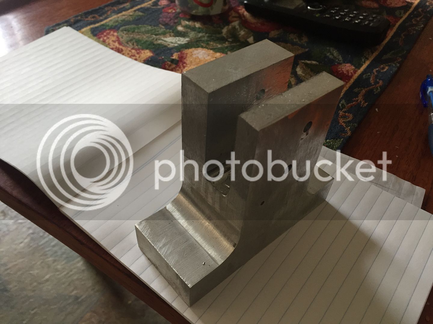
Not much progress to show. Spent two days carving a block of ali into a frame. Very slow going but im reasonably happy with results so far
 
I always seem to have trouble at the point where the large radius transitions into a flat. I always end up having to do more file work there to make it look right than I should have to.
 
Looking good Herbie. You are almost getting close enough to start assembly of the larger pieces. Are you converting to metric as you go along, or building in Imperial (inch)?
 
Its a bit of a mixture here regarding metric/ imperial Brian. Bright mild steel rod is mainly available in imperial but bolts and cap screws are mainly available as metric. Its all a matter of what's available and converting as i go. The actual machining i prefer metric, so when a dimension says 0.313 i just open the digital calipers to that amount and hit the mm/inches button. Although back in my school days everything was in inches , feet and yards etc i dont have any engineering background so mils and thou are still a bit of a mystery to me.
 
My goal for this week is to make the carby. Looks pretty fiddly and complicated to a novice like myself but will give it a try.
 
I see that my vertical engine has won the "Project of the Month" for September. I feel greatly honored by this, even if they have spelled my name wrong.--(I'm sure they will fix that as soon as they see the email I sent them.)---Brian
 
It's fixed. Thanks for the message.
(spell check on Labor Day holiday having a cook out).
 
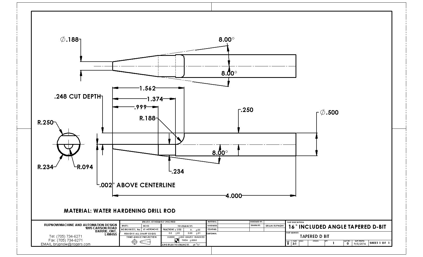
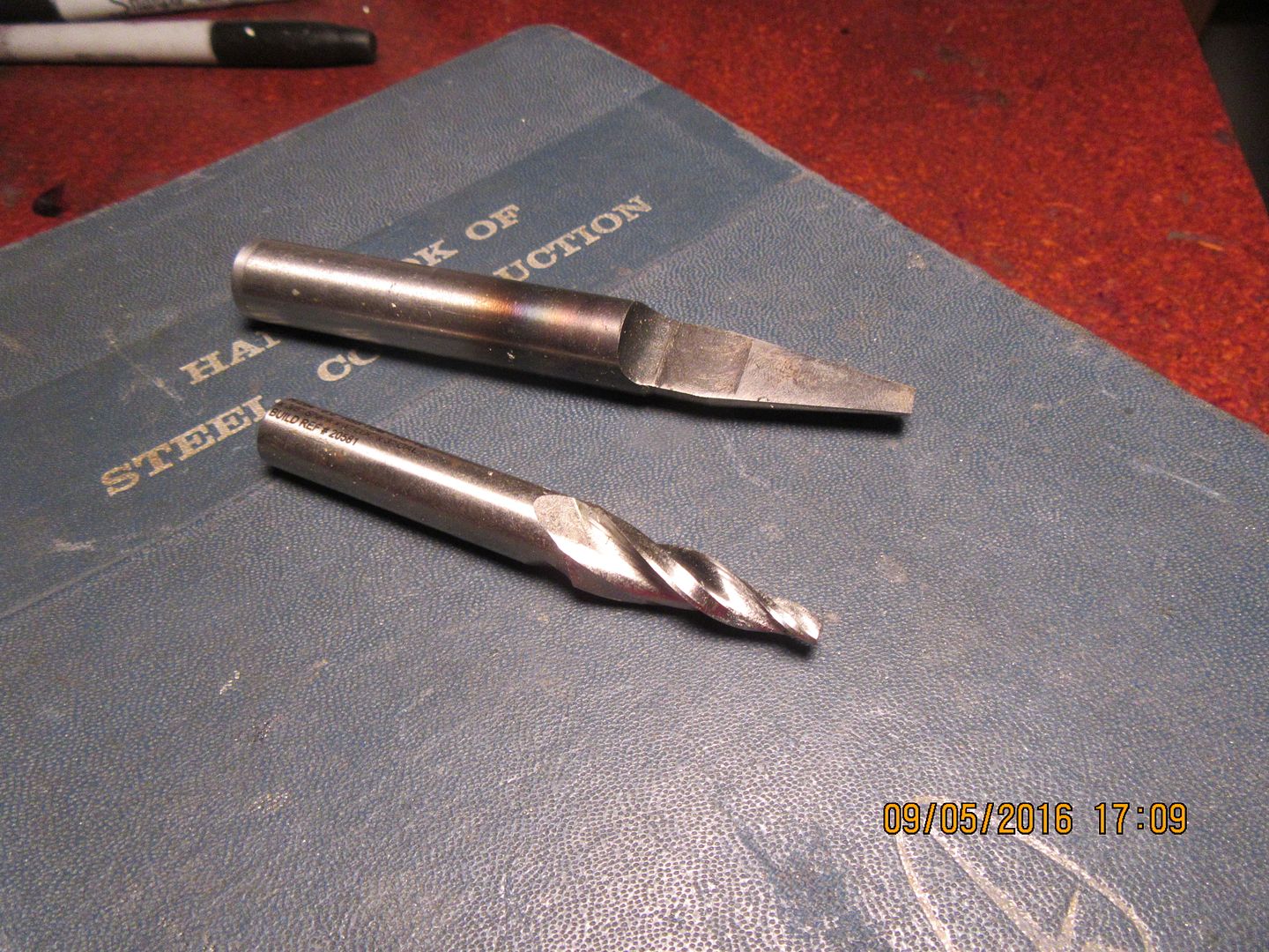
When you go to build the carburetor, that inlet cone on the main body, (that for some perfectly weird reason is dimensioned at 15.77 degrees included angle) isn't all that terribly critical, at least not to two decimal places. If you have a very small boring tool, then you can simply set your topslide over to 8 degrees and bore the taper after the 0.195 diameter thru-hole has been put in. On the other hand, if you don't have a very small boring tool you can build a D-bit like the one in the attached drawing. (which is what I did). There is a little story behind this. I first paid good money for a tapered spiral reamer with a 16 degree included angle to use for this operation. In the process of posting about it, I was warned by Gail from New Mexico that a tapered spiral reamer would "grab" and taking advantage of any backlash in the leadscrew nut would pull itself very deeply into the work. I decided to try this on a test piece of aluminum with a 0.195" hole in it. Gail was right. As soon as it started to cut, it grabbed and pulled itself into the work so badly that it stalled the lathe. so---I built this D bit to do the job, and it worked like a charm. The one critical thing on that carburetor body is that the taper must stop before it reaches the 0.394" center bore of the carburetor. There must be at least some of the 0.195" diameter hole between the end of the taper and that .394" thru-hole, otherwise the carburetor won't work right.

 
Last edited:

Latest posts

Back
Top