Verical hit and miss engine

Home Model Engine Machinist Forum

Help Support Home Model Engine Machinist Forum:

This site may earn a commission from merchant affiliate links, including eBay, Amazon, and others.

Brian Rupnow

Design Engineer
Project of the Month Winner
Joined
May 23, 2008
Messages
15,259
Reaction score
8,544
Location
Barrie, Ontario, Canada
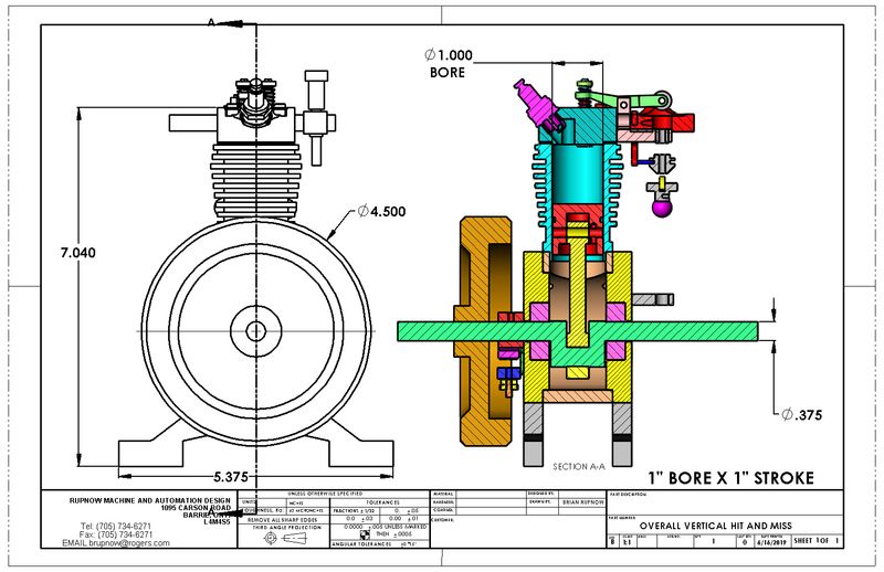
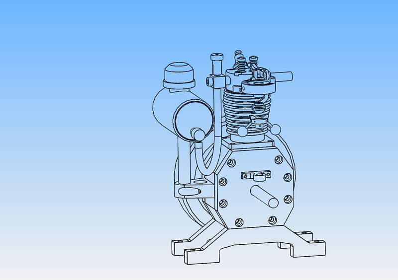
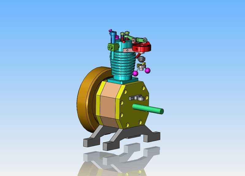
I've caught up on all of my summer chores, and the weather outside is cold and rainy and horrible. I have been bored this week, and when I get bored, I start to design things. I have watched enough YouTube videos of Bob Shores Silver Angel to suss out the hit and miss mechanism, and I am impressed by it. I have ordered a set of 2:1 bevel gears off Ebay and I'm waiting for them to arrive. This engine will have a bore and stroke of 1", and a single flywheel. It will have an oil sump, and the same general configuration as the Angel. I will be using my most current carburetor design (without the offset in the carb body). The valves will be my standard 1/8" stem and 3/8" head. Sparkplug will be a 10 mm CM6 from NGK because they are available at autoparts stores. Probably as the design progresses I will support the horizontal gas tank on a pair of stand-offs from the engine. I do plan on building this engine, but it will take a backseat to other summer things and impending eye surgery in July. This will give me an engine to run my face cam on. Follow along. it should be fun.---Brian
xVI498.jpg
 
I'm going to go with a couple of heavier ball bearings this time. The bearings I have been using are only .906" diameter x 5/16" thick. They get the job done, but I think they are a bit too light, especially with the weight of the flywheels. My new larger bearings are 3/8" i.d. x 1 1/8" o.d. x 3/8" thick. There is not a huge price difference, and I think I'll be a bit happier with them. I haven't modelled in the gears yet, as I haven't received them yet. When I do receive them I will model them and insert them into the 3D assembly. These will not be helical gears like I used in my last two builds, but will be bevel gears. You will also notice that the flywheel is not symmetrical about it's centerline. The ignition points and cam will fit on that side of the engine, and I don't want the flywheel to stick out a long ways from the center of the engine to clear them. By making the flywheel non symmetrical I can fit it in much closer to the engine.
EhbnPf.jpg
 
Last edited:
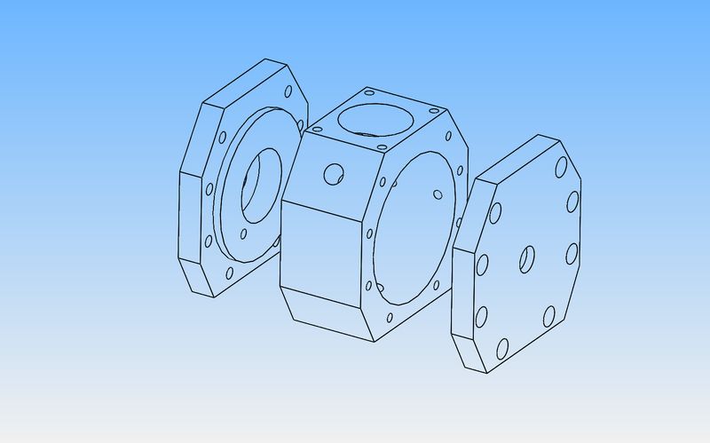
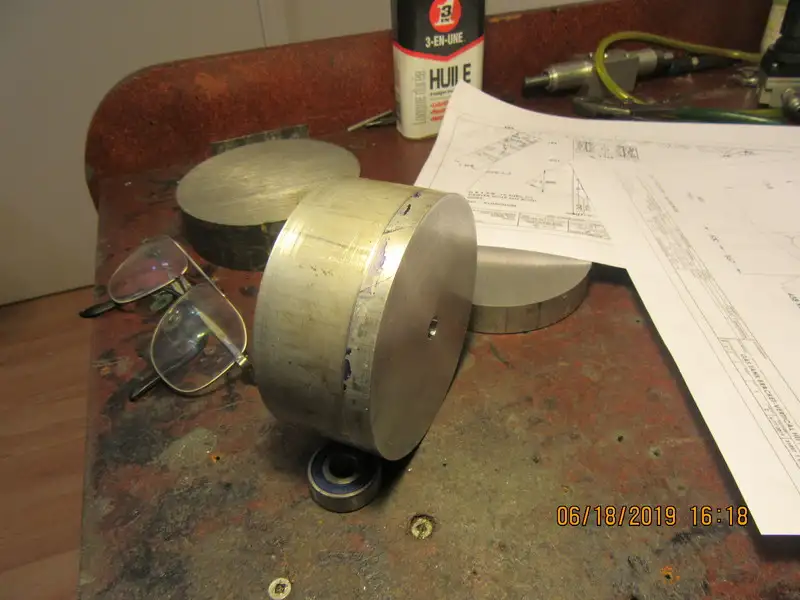
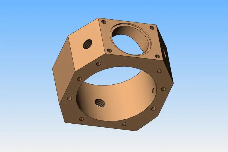
Today I ordered the aluminum to build the crankcase and two side-plates for the engine. All will be cut from 4" diameter round stock. None of these parts will be terribly difficult to make as individual pieces. The difficult part will be to have all of the outer surfaces line up perfectly. The holes in the center of the two outer plates will be 13/32" thru, to give clearance for the 3/8" crankshaft. The center hole in the main body will be 2.3" in diameter to allow for the swing of the crankshaft and big end of the rod. The side-plate on the flywheel side will have two tapped holes which will hold the ignition points. The other side will have two tapped holes for the camshaft support bracket. My plan at the moment (and that may change) is to put the three individual pieces up in the 3 jaw chuck and drill and ream the center holes in all three pieces to 13/32", then make up a 13/32" shoulder bolt long enough to pass thru all three pieces, and clamp them all together with a hex nut on the shoulder bolt. I will need one more bolt thru each side-plate, leading to tapped holes in the main body plate to act as an anti rotation device. I will then bandsaw and mill all three plates locked together to the final outside dimensions. After that, separate the three plates and set the main center body up in the four jaw, pick up on the reamed center hole to find exact center, then bore the hole out to 2.3". The counterbored bolt holes in the outer plates and the tapped holes for them in the center main body can be put in after the fact.
8RODEx.jpg
 
Jim-Don't apologize. For me it is as easy as breathing, but I have been using this program (Solidworks) for about 19 years. I spent 32 years on a drafting table, then 3 years learning and using Autocad 2D before learning to use 3D. If you are already proficient with a 2D software like Autocad, then it's not horribly hard to start using a 3D program. If you have no background in any software drawing package, it's pretty tough.---Brian
 
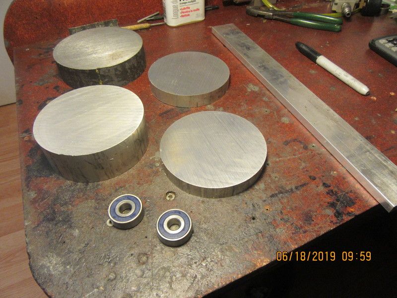
So--There we have 95% of the material required to build this engine. The three pieces of 4" dia. aluminum which will become the main center body and the two side plates, the flatbar to make the "feet", and the 4 1/2" diameter piece of 1018 round stock that will become the flywheel. That cost me $30, and the two new bearings cost $20.
Pu2oBS.jpg
 
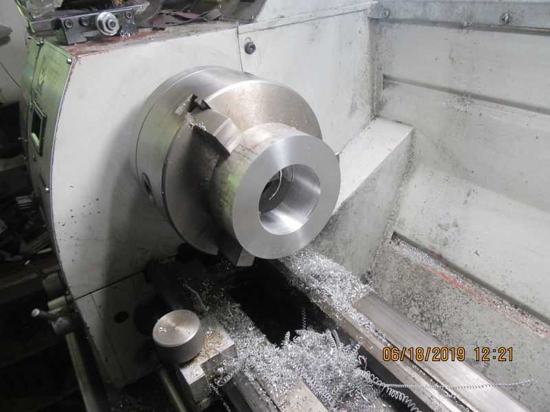
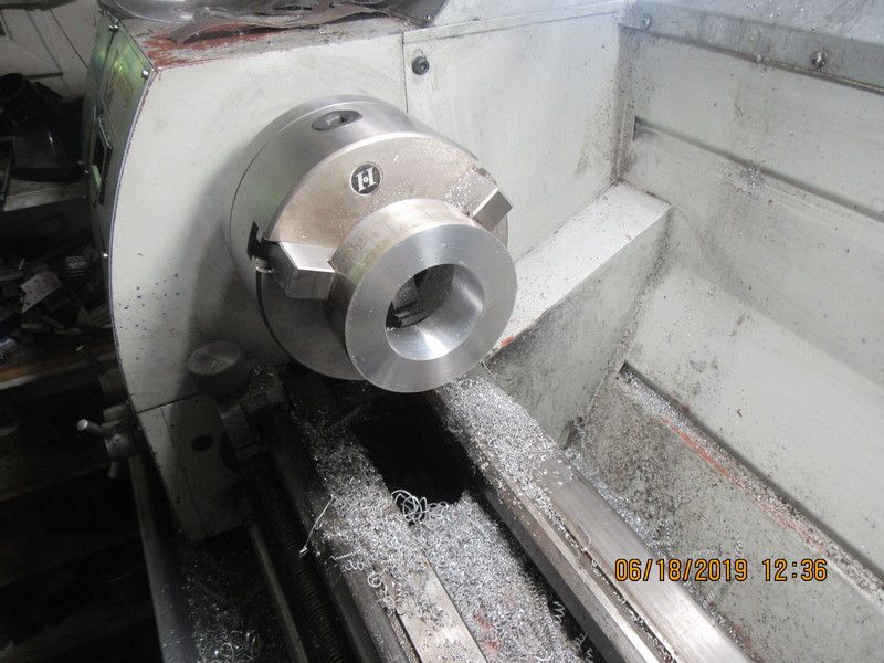
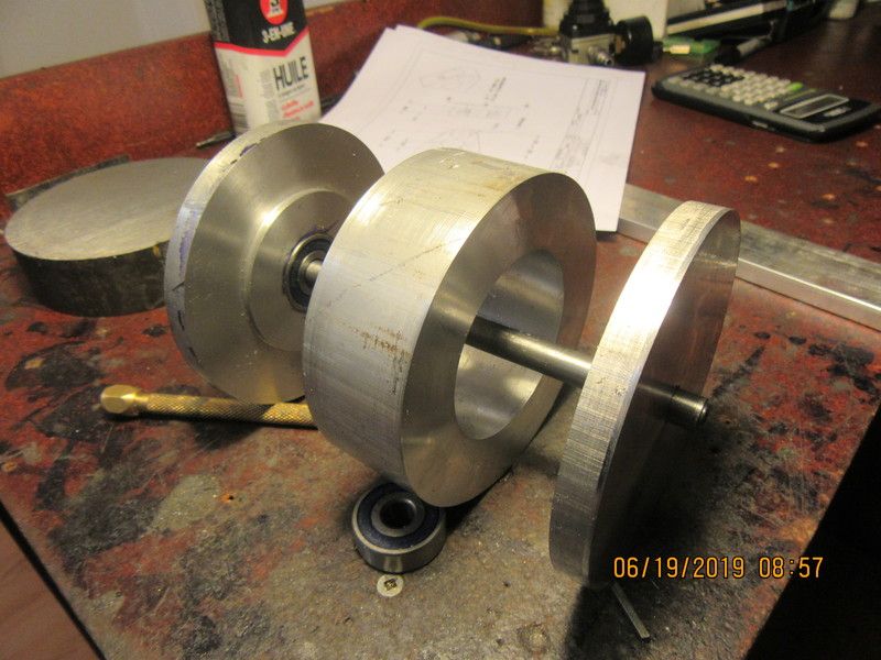
At the last moment I decided not to machine things as I had shown in an earlier post. With the main body held in the 3 jaw chuck I faced the exposed side, then drilled and bored the center hole in one set-up. Then I flipped it around 180 degrees in the 3 jaw, made sure that the previously "faced" side was up tight against the jaws, and faced the other side. The sideplates both have a "register diameter" that will fit into this hole in the main center piece.
Aod0r6.jpg

vXFF4x.jpg
 
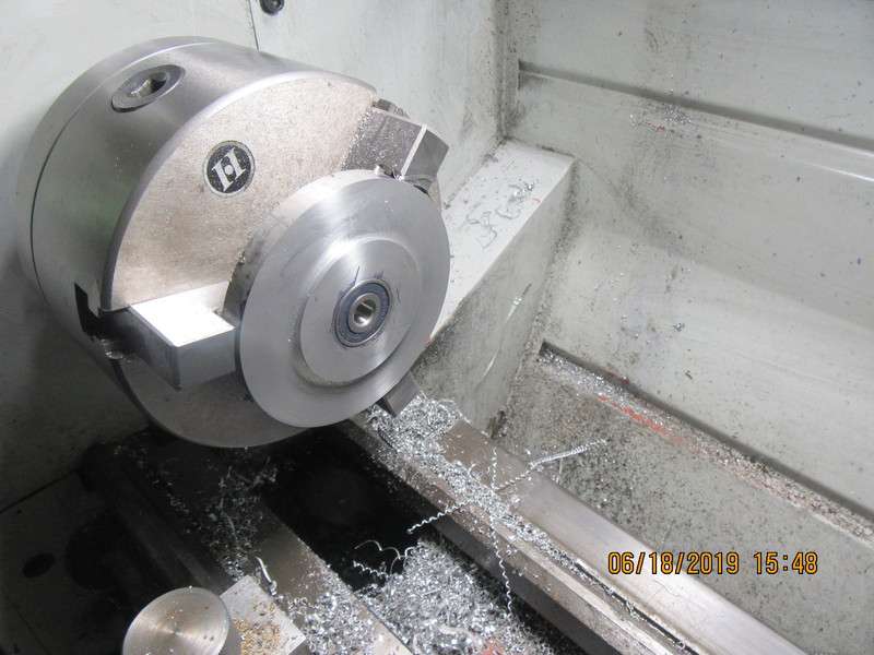
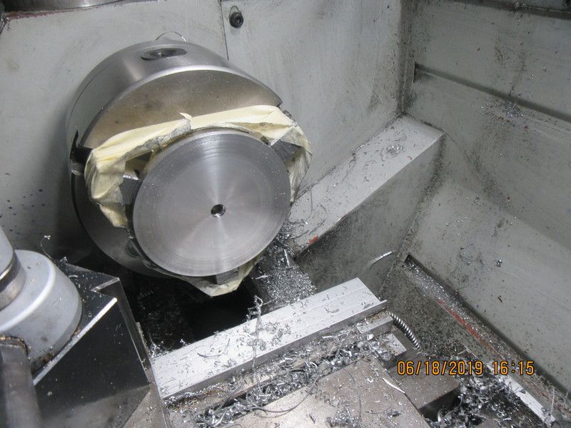
First side-plate is machined and all is well. The tape is around the chuck to keep some spacers between the chuck jaw and the part from flying out and conking me in the head. Will do the second side plate tomorrow.
xYPMGe.jpg

Q1LspJ.jpg

cG3fgE.jpg
 
Well sir!!--that went amazingly well. Next step will be to drill and tap 16 holes and get everything bolted together. Once that detail is looked after I will begin profiling all 3 components together.
6VDUge.jpg
 
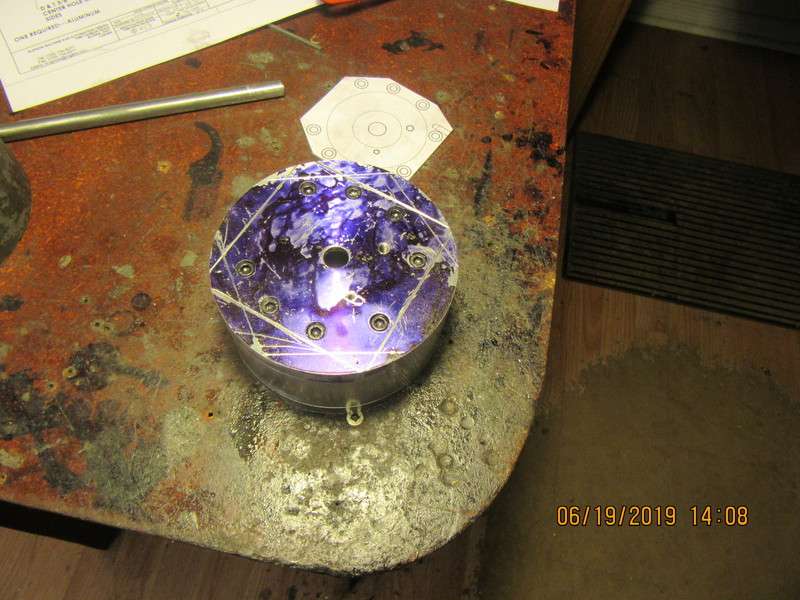
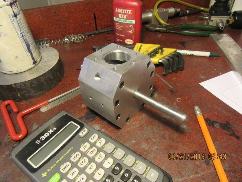
Everything has been drilled, counterbored, and tapped. I had the part set up and centered in the milling machine to do the drilling. Before tearing down my set-up, I put a sharp pointed rod in the mill chuck and used the DRO to measure off the distance to four of the "sides" in the X and Y axis, then kept a little down-pressure on the pointed end while I cranked the mill table in X and Y to mark the lines. Then I printed off a 1:1 scale drawing of one of the sides, glued it to cardboard, and lined the cardboard up with the existing marked lines to allow me to mark the other four lines. I see a world of band-sawing in my future!!!
TY7VyK.jpg
 
So--There we have 95% of the material required to build this engine. The three pieces of 4" dia. aluminum which will become the main center body and the two side plates, the flatbar to make the "feet", and the 4 1/2" diameter piece of 1018 round stock that will become the flywheel. That cost me $30, and the two new bearings cost $20.
Pu2oBS.jpg
Brian,
Who supplied your material ?
I'm on the left coast and was recently quoted 60 bucks for a 4 by 4 piece of round 6061.

John
 
A guy right here in Barrie has a one man company called A to Z Metals. His pricing is very good and he saws material to whatever length I ask for.
 
At the very last moment, I decided to put an o-ring groove in the top of the main body. This engine will have a "wet" crankcase, and it's either go with an o-ring or put a gasket between the main body and the cylinder to prevent oil leaks.
VYYkk5.jpg
 
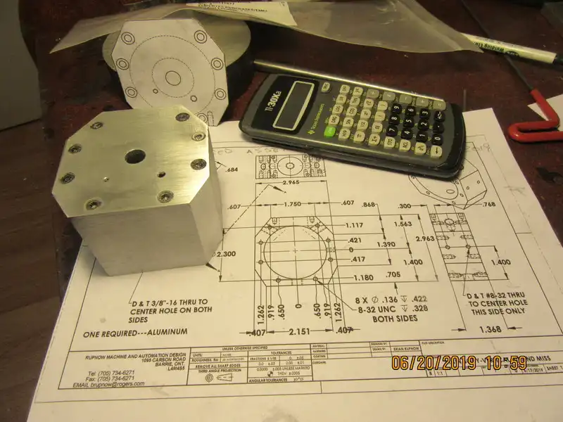
So there we have it. the main crankcase and side-plates are finished. I was going to make the cast iron cylinder next, but there is a caveat. There has to be a cut on one side of the fins to allow clearance for the governor balls, and since I don't have the gears yet, I can't establish that dimension until the gears arive hear and can model them. Not to fear though. There are plenty of other small parts to make while I wait for the gears to show up.
N9skyy.jpg
 
looking good. either that's a really large calculator or a very small crank case. will you be splash oiling with a tang on the bottom of the rod like a birggs and strattor or anything like that?
 

Latest posts

Back
Top