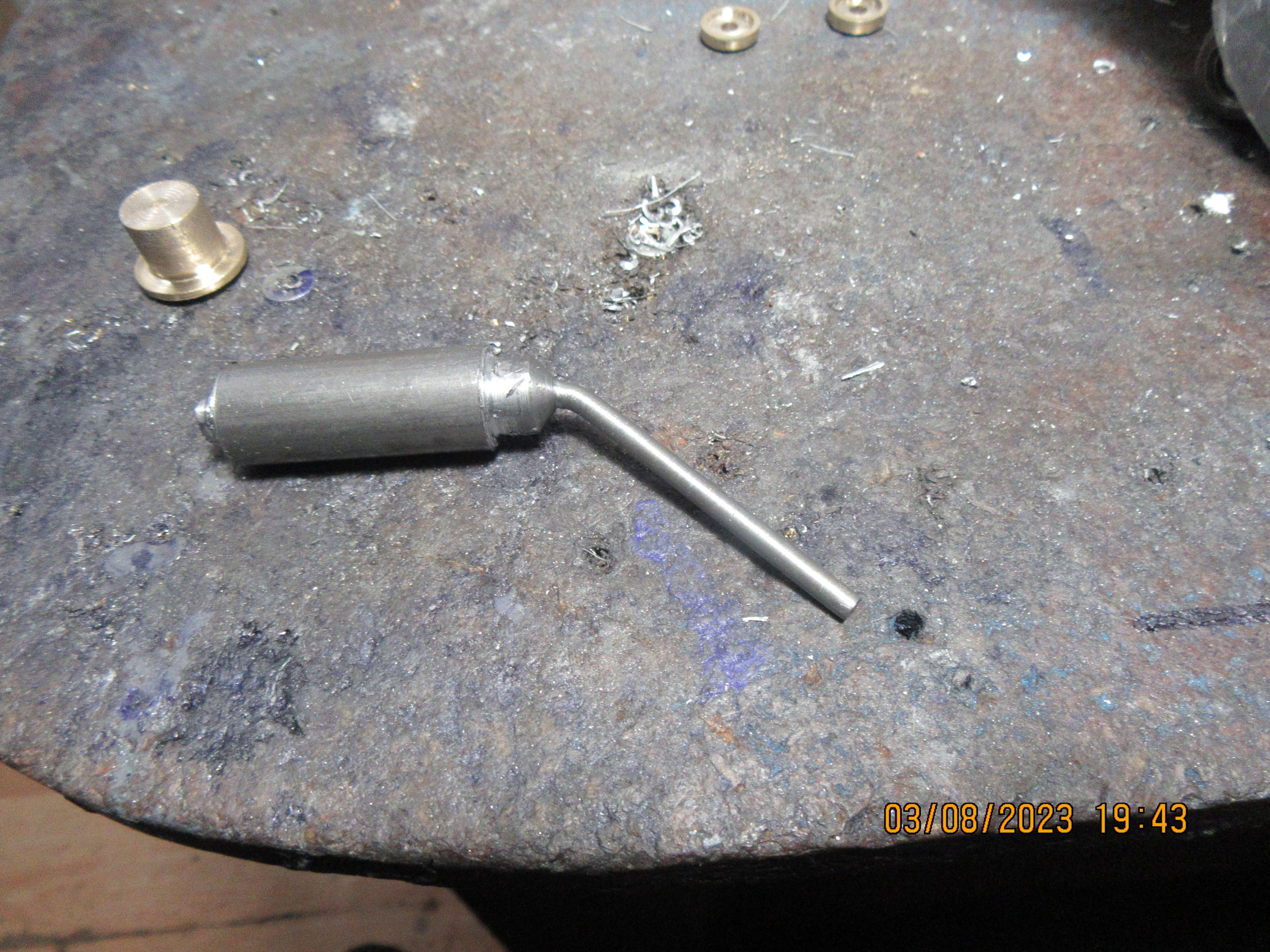
For a minute there, I was really excited to read about a new, 45° "angle valve." Seems like the next logical evolution of the model IC engine, given how much easier it is to create that sort of valve than the boring straight ones!Today I almost made a valve-----
You are using an out of date browser. It may not display this or other websites correctly.
You should upgrade or use an alternative browser.
You should upgrade or use an alternative browser.
Flathead hit and miss engine???
- Thread starter Brian Rupnow
- Start date

Help Support Home Model Engine Machinist Forum:
This site may earn a commission from merchant affiliate
links, including eBay, Amazon, and others.
Have you ever considered the swing valve? - It uses a "bent" stem, and the rocker lifts it into place rather than it sliding up a valve guide....
Allowed engines to rev higher than conventional spring loaded poppet valves.
As far as I know, only one guy did it (1950s? - or 60s?) and won a few big races with his bikes, until factory budgets beat him. But I can't find the reference... magazine article....
K2
Allowed engines to rev higher than conventional spring loaded poppet valves.
As far as I know, only one guy did it (1950s? - or 60s?) and won a few big races with his bikes, until factory budgets beat him. But I can't find the reference... magazine article....
K2
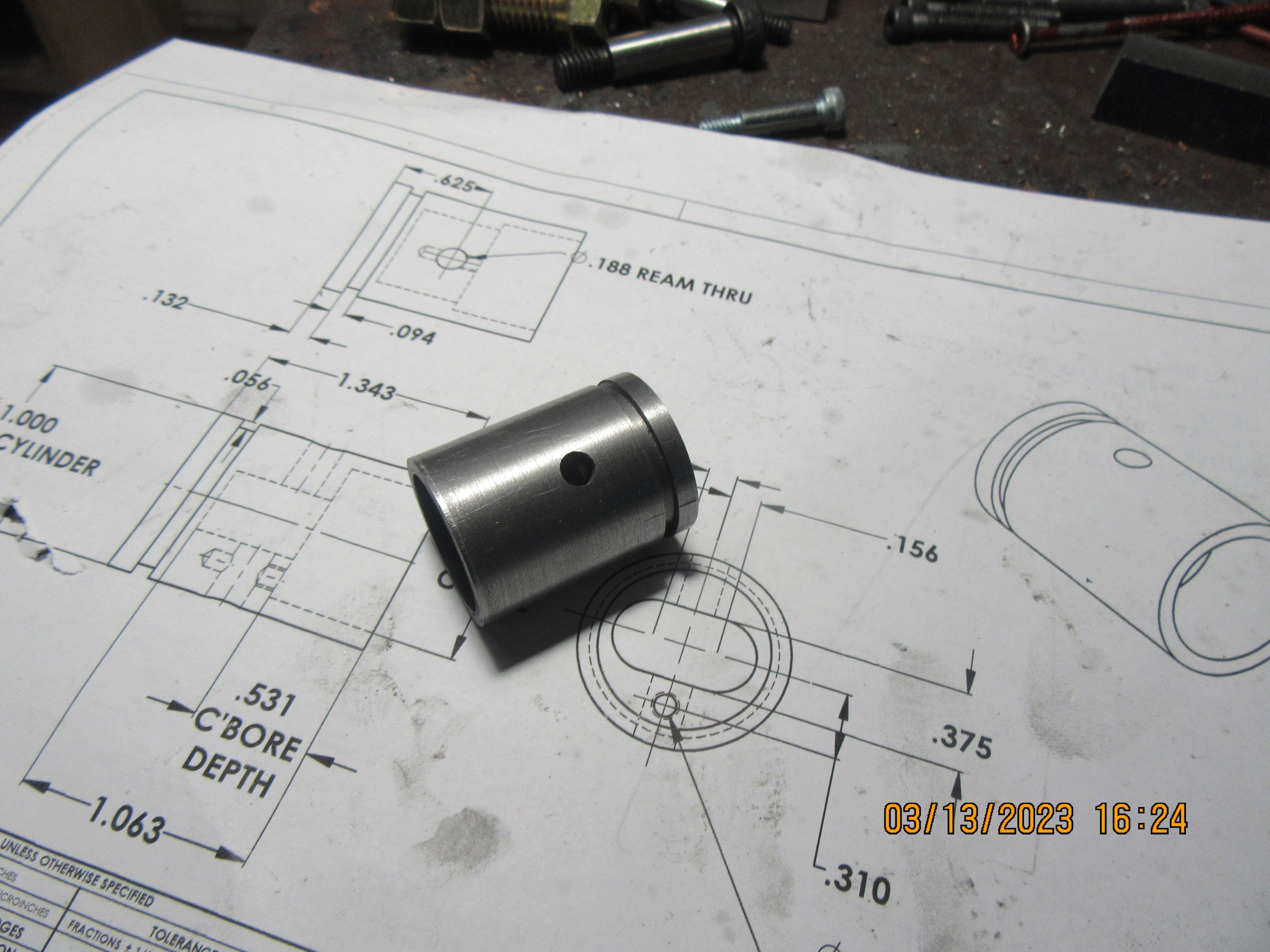
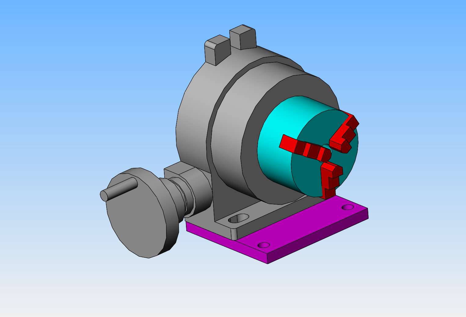
So what did I accomplish today?--On the engine, not much. I finished the piston. But--I did modify my rotary table!! The table I have has two bolts that attach it to the milling machine table, and they are just horrible to get at. It has bothered me for 13 years, and today I added a 1/2" steel plate to the bottom of it to get the two bolt holes moved out to where they are much, much easier to get at. The attached model shows my rotary table with the two inaccessible bolt holes visible. The passion pink plate added to the underside gets those bolt holes right out where God and everybody can see them. The two original bolt holes now have bolts that thread into the 1/2" plate.


Nice one Brian! A worthwhile modification. I may do the same myself?
But my biggest bug-bear is aligning the centre of the chuck to the centre of the rotary table. My chuck is a bit eccentric, as am I. It is a problem of accessibility of the mounting bolts for holding the chuck mounting plate to the Tee-slots of the rotary table that I must resolve...
K2
But my biggest bug-bear is aligning the centre of the chuck to the centre of the rotary table. My chuck is a bit eccentric, as am I. It is a problem of accessibility of the mounting bolts for holding the chuck mounting plate to the Tee-slots of the rotary table that I must resolve...
K2
Either bore a hole in the chuck backplate and use a spigot in the R/T's hole or if there is enough thickness to the backplate turn a spigot on that to locate directly into the R/T's hole. I have one of each to suit my two rotary tables and the chucks never comes off their backplates so if you machine the backplate in situe it will be true to the jaws.
Thanks Jason.
Chuck to backplate is good. But backplate to rotary table is via 3 x Tee-slotted holes, with no register for alignment - so I need to use a clock on a standard bar set in the chuck. But just nipping the bolts (actually hex. socket set screws into the Tee-slot nuts) always just knocks it a tad off true. - I need patience, more patience and a final bit of patience as well! The chuck is also a bit worn, which doesn't help. I'll get there...
K2

$25.34
$34.99
Peachtree Woodworking Supply Bowl Sander Tool Kit w/Dual Bearing Head & Hardwood Handle, 42 Pieces Wood Sander Set, 2 Hook & Loop Sanding Disc Sandpaper Assortment, 1/4 Mandrel Bowl Sander
Peachtree Woodworking Supply Inc

$40.02
$49.99
Becker CAD 12 3D - professional CAD software for 2D + 3D design and modelling - for 3 PCs - 100% compatible with AutoCAD
momox Shop

$599.00
$649.00
FoxAlien Masuter Pro CNC Router Machine, Upgraded 3-Axis Engraving All-Metal Milling Machine for Wood Acrylic MDF Nylon Carving Cutting
FoxAlien Official

$99.99
AHS Outdoor Wood Boiler Yearly Maintenance Kit with Water Treatment - ProTech 300 & Test Kit
Alternative Heating & Supplies
![DreamPlan Home Design and Landscaping Software Free for Windows [PC Download]](https://m.media-amazon.com/images/I/51kvZH2dVLL._SL500_.jpg)
$0.00
DreamPlan Home Design and Landscaping Software Free for Windows [PC Download]
Amazon.com Services LLC

$104.99
Sunnytech Hot Air Stirling Engine Motor Steam Heat Education Model Toy Kit M16-CF
stirlingtechonline

$6.06
$19.95
Sheds & Garages: Building Ideas and Plans for Every Shape of Storage Structure
ZBK Wholesale
Just get some tee bolts and save yourself some grief.
It was the backplate to rotary table I was talking about,
Either have a spigot on the backplate to locate in the rotary table like this wher the RT has a parallel sided recess

Or if you have an MT socket in the table then use a blank end arbor to make a spigot you can then make various bushes for parts or to locate a hole in your backplate. Both ways the chuck is registered to the RT in much the same way as the register in a chuck locates it to a backplate

Either have a spigot on the backplate to locate in the rotary table like this wher the RT has a parallel sided recess

Or if you have an MT socket in the table then use a blank end arbor to make a spigot you can then make various bushes for parts or to locate a hole in your backplate. Both ways the chuck is registered to the RT in much the same way as the register in a chuck locates it to a backplate

Aye, Many ways to slaughter this porky problem.
I just need to get motivated and do it.
Thanks for suggestions,
K2
I just need to get motivated and do it.
Thanks for suggestions,
K2
Here we have a 5 hour connecting rod. I worked on it an hour last night and then four hours today. It looks very robust. If I were going to make connecting rods for a living, I'd have to speed up my process or go hungry a lot of the time.
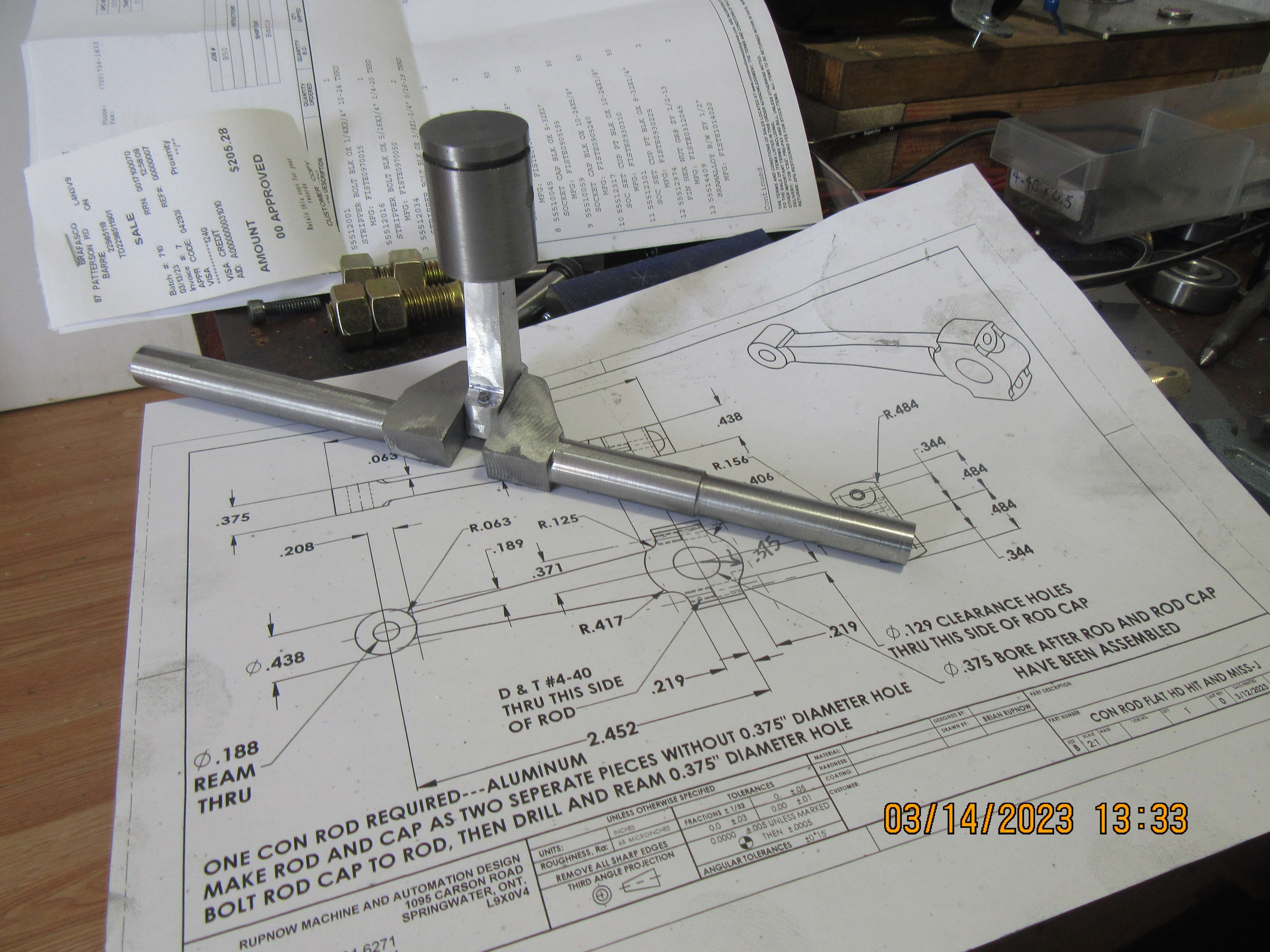

Making the con rod was one thing. Getting it to fit where I wanted it to and being able to revolve the crankshaft through 360 degrees turned out to be a major battle. After the first five assembly's and diss-assembly's, I started coating the con rod with layout dye, assembling it, rotating the crankshaft until it went "clunk" and then disassembling things to see where the layout dye was marked up. I kept filing away on the con rod until it began to look like a tapered cylinder, but eventually I found the sweet spot where the crankshaft rotated through 360 degrees without any interferance. At that point, I coated the outside diameter of the ball bearings with j.b.weld, shoved them into the crankcase cavities which were prepared for them, spun everything by hand one more time just to be "Damned sure" and left it to cure overnight.
At a glance I thought the con-rod looked "a bit beefy" - but then I thought "this is Brian's engine - he will have designed it and checked the CAD for clearances..."
But I understand where you are coming from... I did exactly the same building a Stuart steam engine (single acting 180degree crank twin) - where the con-rod castings were missing, so I "copied the drawing shape" and made 2 conrods - that fouled the bottom of the cylinder and needed fettling - like yours. So I can say "been there, done that".
Thanks Brian.
K2
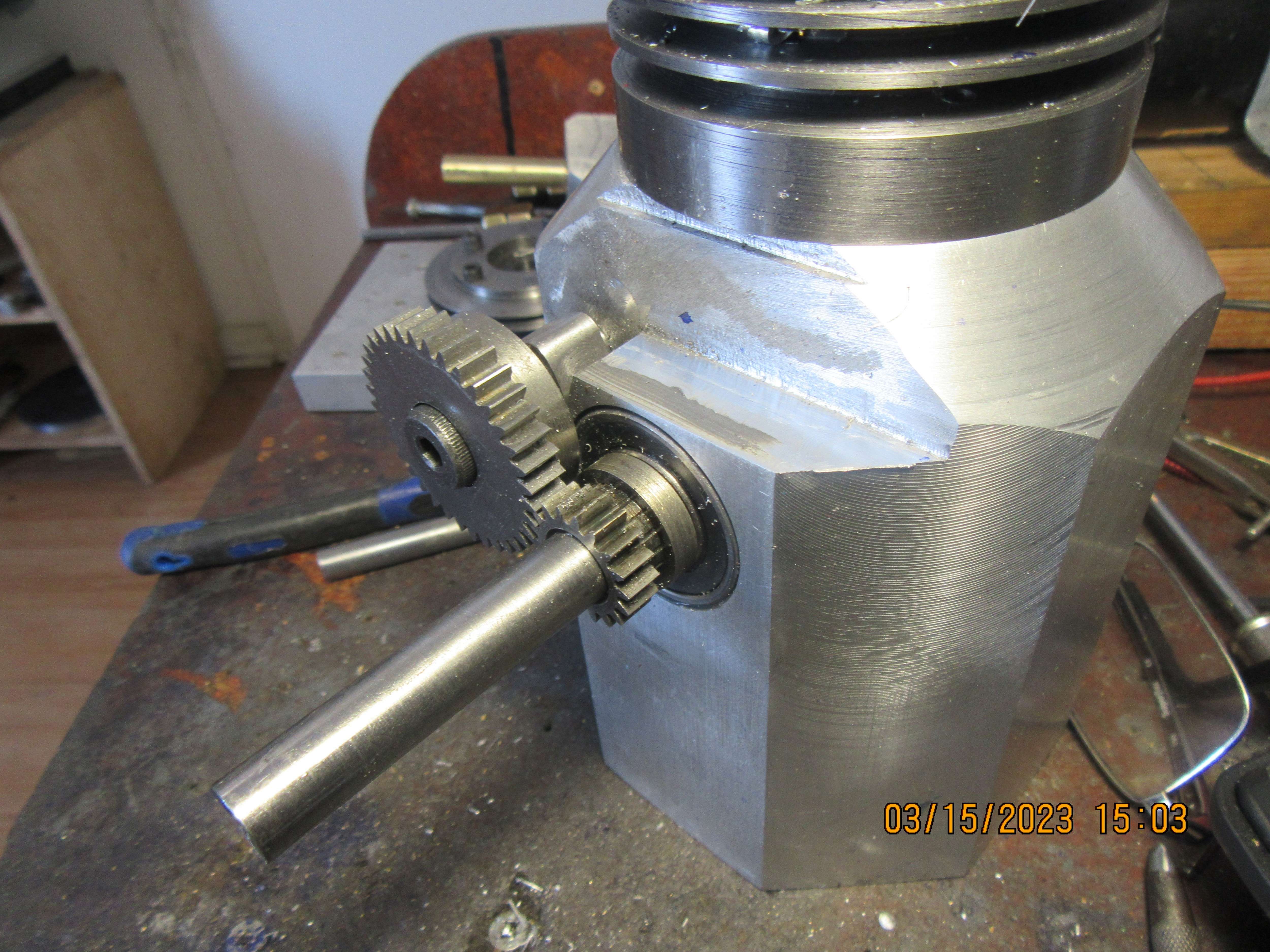
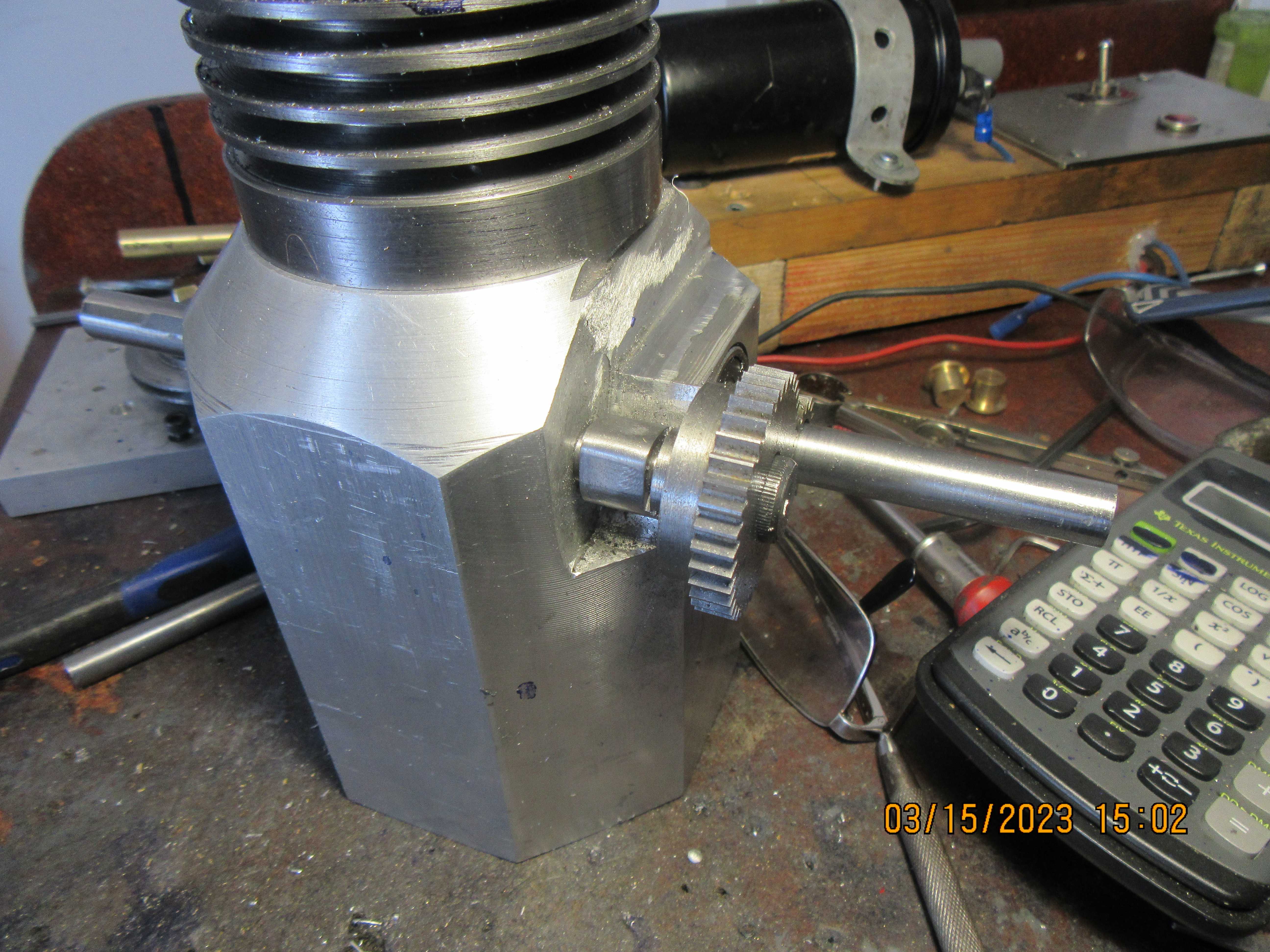
Today the cam was finished and the cam and gears were mounted in their respective positions. The crankcase was drilled and tapped for the 3/8" shoulder bolt that supports them, and I am happy to announce that the gears mesh just fine with no "sticky" spots. I got lucky with the cam---Since it has a hardened wheel riding on it as a cam follower, I didn't require any flank radius on the cam. That makes the cam much easier to machine.


- Joined
- Sep 2, 2011
- Messages
- 1,406
- Reaction score
- 413
Hi Brian, just wanted to say ive been watching and like what you are doing with this so far. i know you like to know if people are interested or not so just wanted to post that i like it and keep the pictures coming.
Thank you for that Werowance. I'm glad you are watching and enjoying.---Brian
Today was assembly day. All the pieces fit where they are supposed to and everything thats supposed to go up and down and round and round seems to be doing it. This is an exciting milestone in the build, and after today I will be working on the governor mechanism that locks out the exhaust valve during the "miss" cycles.
Whoever it was that said "Close only counts in horseshoes and hand grenades" should have also said something about model engines. Today I machined the support post which supports the hit and miss mechanism, and it clears the outer edge of the timing gear teeth by about 0.080". Thats okay. The timing gear only rotates and the post doesn't move, so they're never going to bump heads. My cad model told me that they would clear okay, but I never really believe it until I have the parts machined and assembled.----
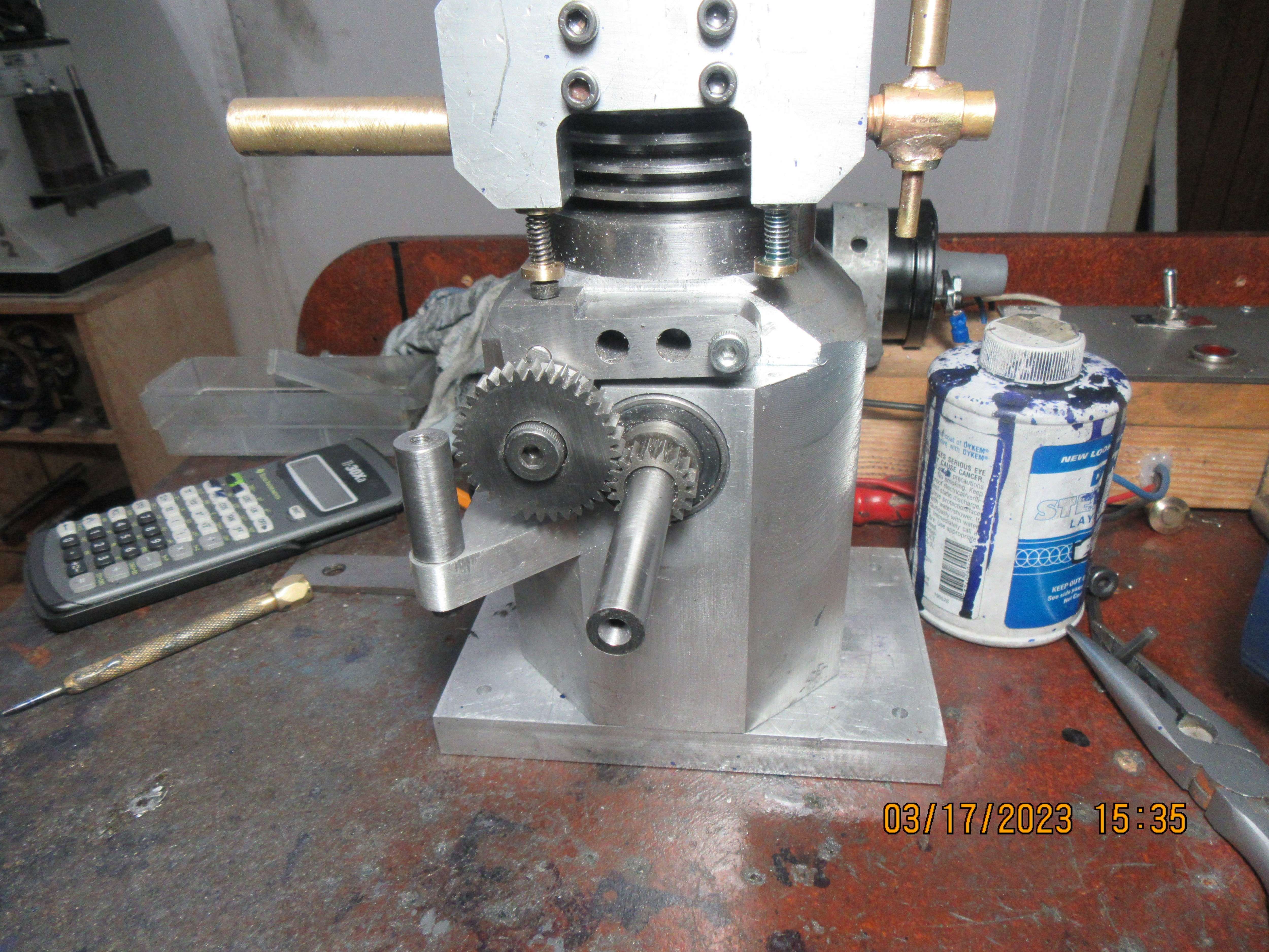

I wanted to put a second "Like" for the picture chowing a "proper" calculator, as well! - It simply demonstrates a necessary part of the process...= "check, check, and check again!" These "Old" simple calculators are a very quick way to reliably add dimensions that stack-up as well as doing a host of other sums. The display on my 1970s Sharp D.A.L. is starting to lose pixels, but after 4 batteries in >40 years I guess Sharp would say the guarantee has now expired?
K2
K2
Steamchick--I started out in 1965 when we all used "Smoleys Four Combined Tables of Logarithmic" functions and a slide rule.--I couldn't live without my pocket calculator.---Brian
£4.50 from 3b@y and a new calculator is "in the post".
Similar threads
- Replies
- 0
- Views
- 956
- Replies
- 19
- Views
- 6K


![Learning Revit MEP 2014 [Online Code]](https://m.media-amazon.com/images/I/61vjG-sEuQL._SL500_.jpg)


![Learning AutoCAD Civil 3D 2014 [Online Code]](https://m.media-amazon.com/images/I/51F3yi9fokL._SL500_.jpg)

