Flathead hit and miss engine???

Home Model Engine Machinist Forum

Help Support Home Model Engine Machinist Forum:

This site may earn a commission from merchant affiliate links, including eBay, Amazon, and others.
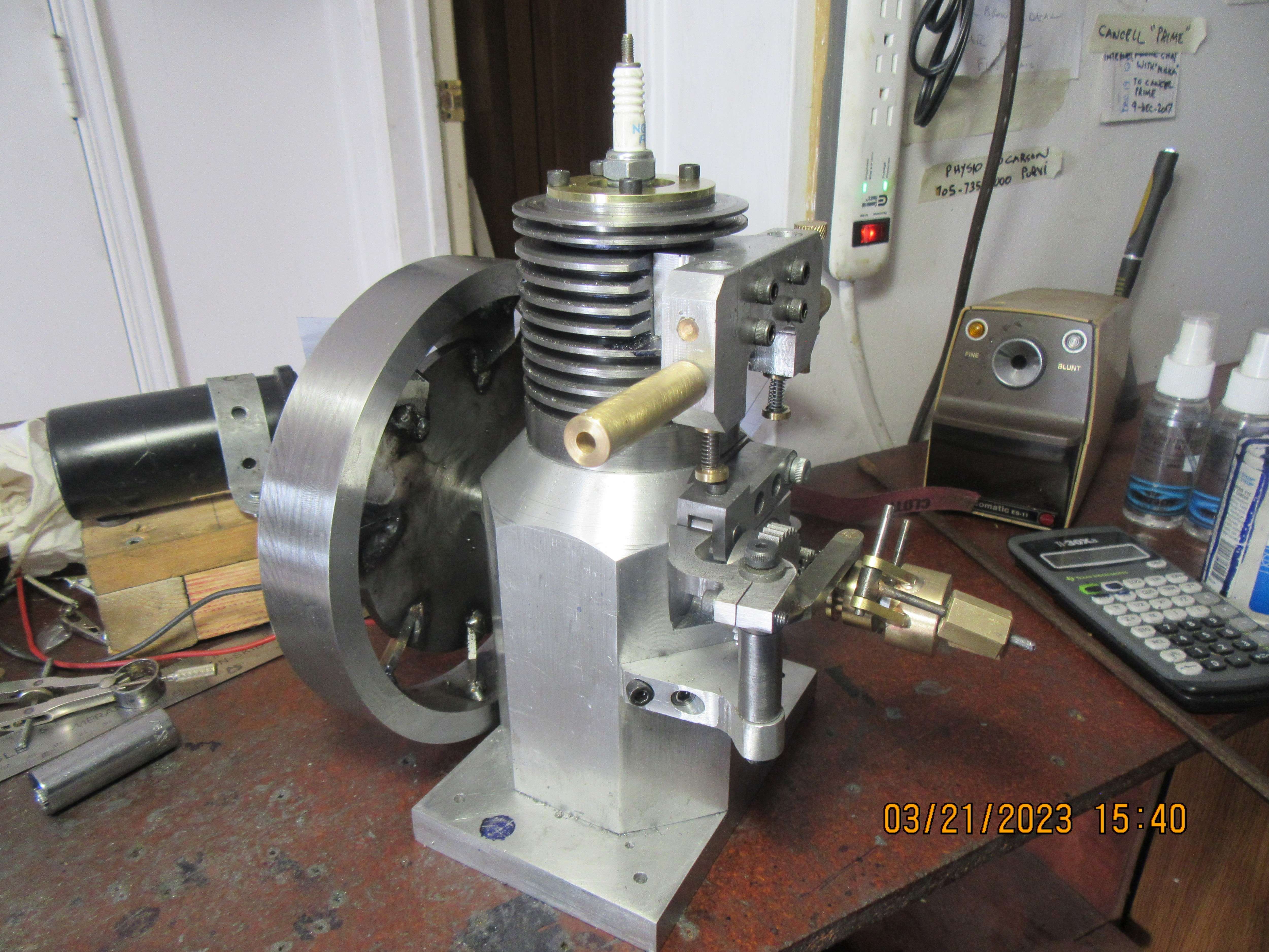
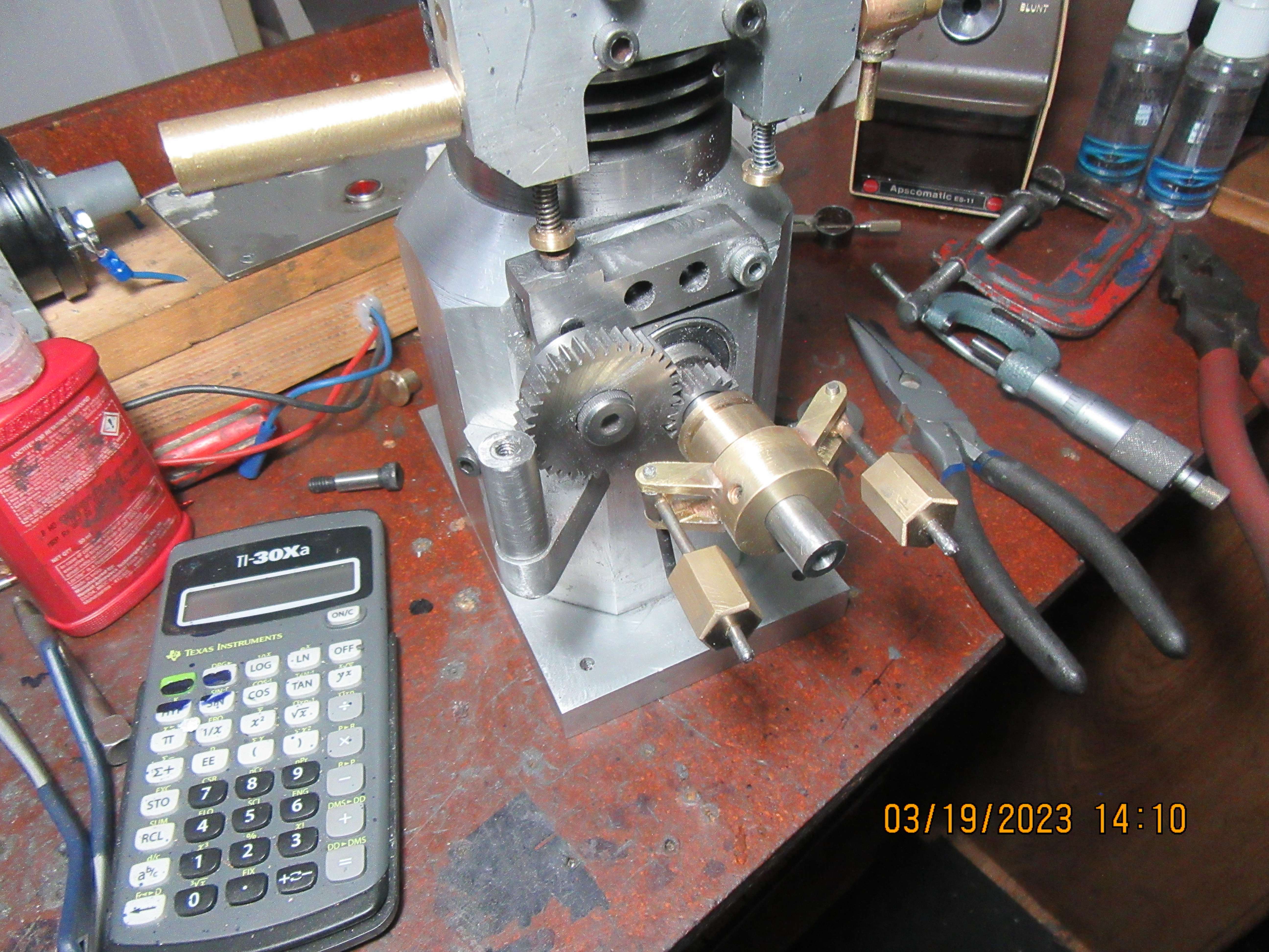
Today I finished machining the governor and installed it. This is not a terribly challenging part of the build, but it is right on the edge of what I can see comfortably. It works. As the governor weights fly outward from centrifugal force, the spool on the crankshaft travels about 3/16", which is sufficient to move the "hit and miss lever" in and out to hold the exhaust valve open. Tomorrow I will work on the actual "hit and miss" lever.
ui4JYp.jpg
 
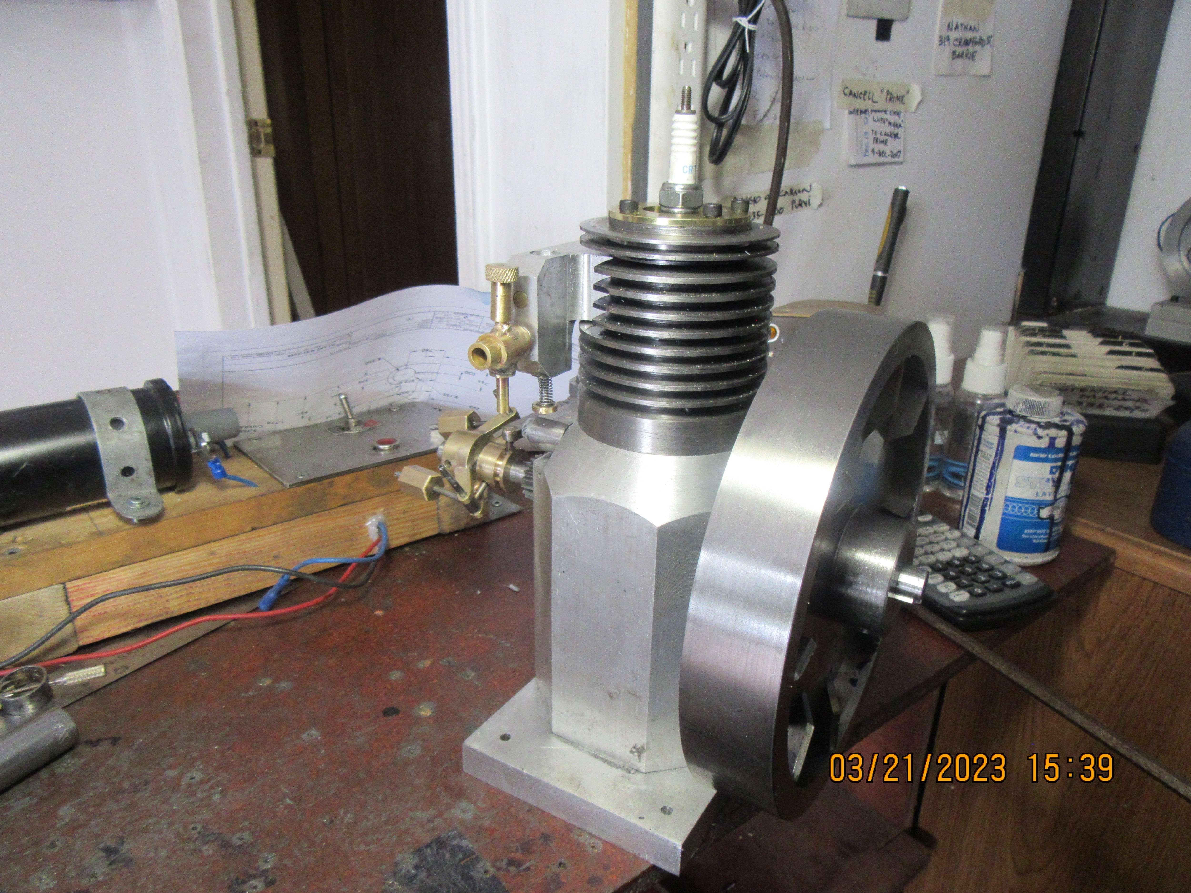
At this point in the build, I'm getting right down to the nitty-gritty of things. The only remaining part to be made is the hit and miss mechanism. I think my best option is to make the actual hit and miss lever adjustable, both vertically and angle-wise in relationship to the part that rides in the governor spool on the crankshaft. I have roughed out something, and decided that it will catch under a notch filed in the swing arm that lifts the exhaust valve. Once I have adjusted it for the best possible hit and miss action, I may solder it in position and cut off the portion that holds the clamp bolt.
8Q1IHJ.jpg

2ZONLc.jpg
 
Today was assembly day. All the pieces fit where they are supposed to and everything thats supposed to go up and down and round and round seems to be doing it. This is an exciting milestone in the build, and after today I will be working on the governor mechanism that locks out the exhaust valve during the "miss" cycles.

I enjoy your builds very much and I always learn.
 
Brian,
Your mention of Log Tables and slide-rules brings back memories of using both during my Secondary Tech School days. Still got the slide-rule and (I think?) the log tables. Rarely used them in working life as a textile dyer. Calculators on the desk ruined my already shaky mental arithmatic. (sigh!)
 
Hi JohnB.. been there, joined the club. But I use pencil and paper, chalk and blackboard, and calculator a lot. Slide rule rarely, only a few times a year.
Even so, I machined a supposedly symmetrical part by winding the wheel on my milling machine 5 times from centre to the left, and 6 times to the right of centre.. Doooh! Both should have been 6 times! The 3mm hole is exactly 2.50mm closer to centre than it should be. Everything fits but it looks ODD!
No calculator or other tool can manage to overcome my incompetance.
K2
 
I lost my sliderule years ago. When I started my apprenticeship my big company was doing a lot of structural steel for skyscrapers and towers for mining companies. The structural engineers gave us the distance between floors and the space between main support columns, and it was up to us apprentices to calculate the length of the diagonal braces between them and the bolted connections at both ends. This was all done using logarithmic tables, as pocket calculators hadn't been invented yet. I done more math in that first five years than I have done in the rest of my career.
 
I found my old slide rule a year or so ago and showed it to my grandson. I bought it about 1960 when I was ain college for about $25 which was a lot of money when the average wage was about $100/week. In one of my first jobs we had to recap costs/profit on our jobs. Every purchase was marked up 15% so we used our slide rule to divide by 85 and it was close enough for us in the engineering department. Accounting had a Monroe Calculator which cost too much for the engineering department. That did not stop the accountant from complaining about our inaccurate figures. As revenge we used to go by his desk when he left for the rest room and divide by zero which just made the clunk-clunk Monroe go into an endless loop.

In another of my later jobs about 1970 my boss bought a small hand held calculator for $250 which was equivalent to about a $25 unit today. The first week he used it to figure out payroll and paid me $10 too much. The next week he went on vacation and the other boss just copied what was done the week before so I again got an extra $10. The following week the first boss came back and just copied what was done the week before so I again got an extra $10. I told him that I really liked his new calculator and in another 21 weeks I would own one of my own.
 
I lost my sliderule years ago.
My first one, a cheap plastic version, disappeared in '71 or 2. I bought a replacement "for fun" in about '84. Ironically, it was marked with the company logo of Collins Radio, whom I went to work for in '96 and retired from almost 20 years later.

I still have it, two feet from my left hand as I type.
 
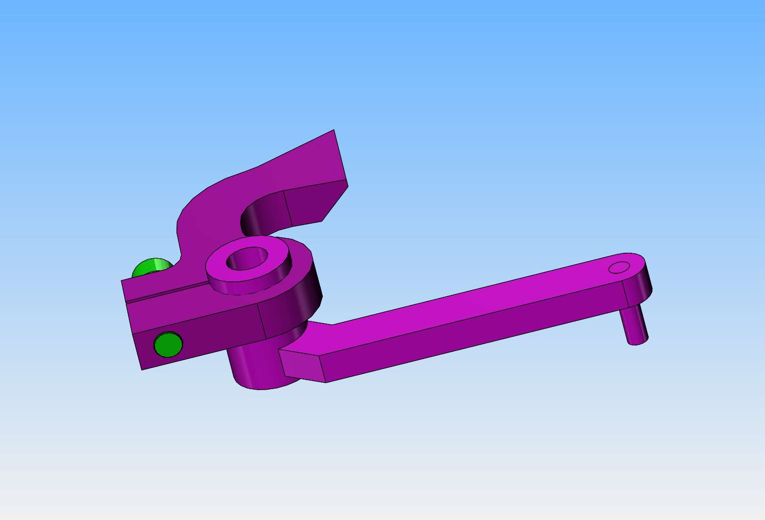
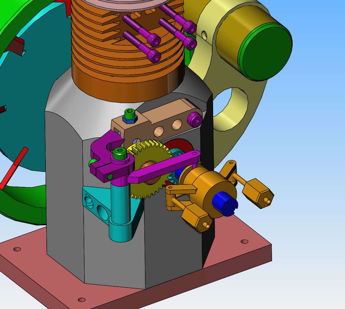
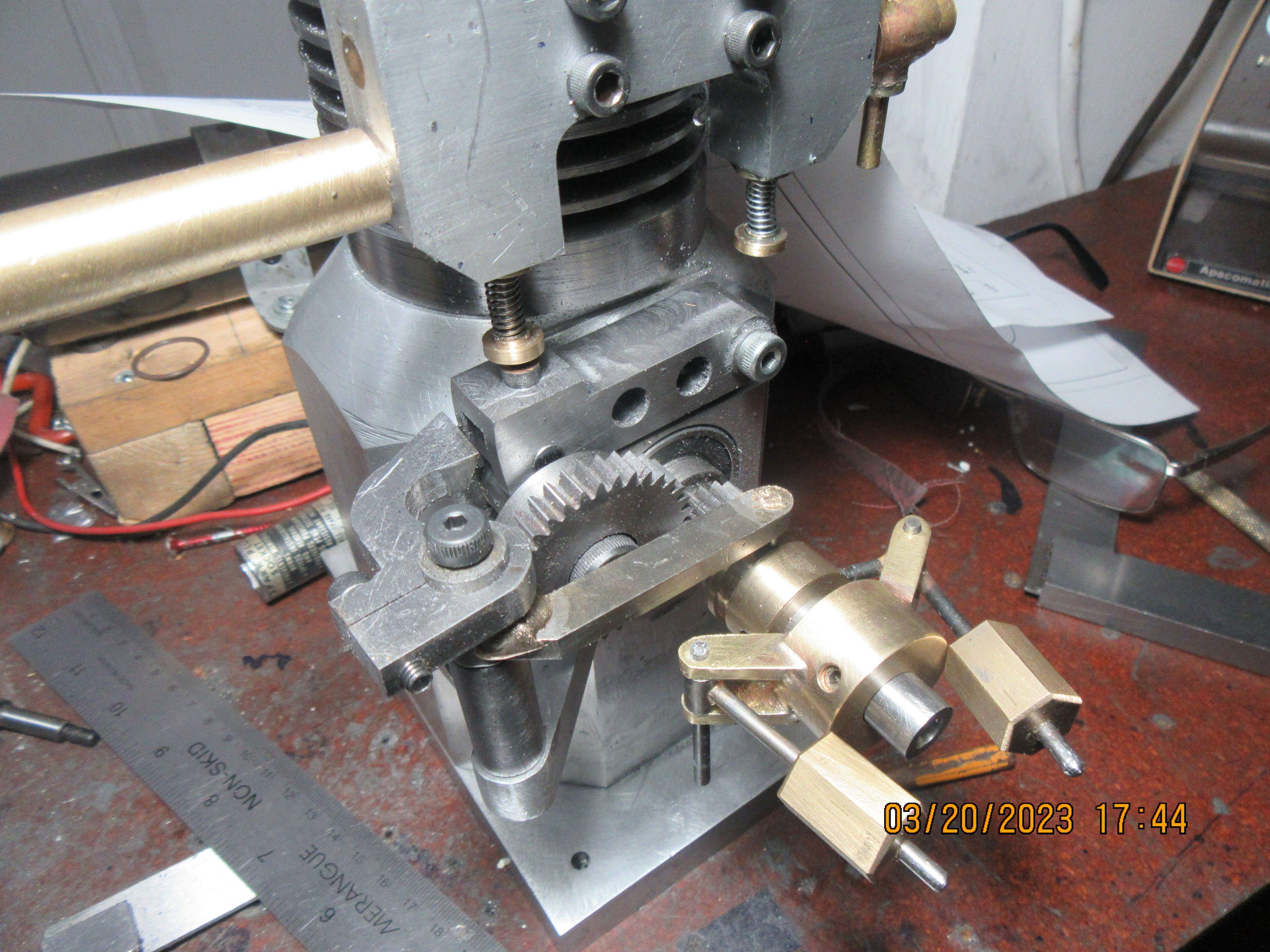
Today I machined the hit and miss mechanism and mounted it to the engine. I think it will work alright.--When I move the governor weights by had the weird shaped arm does easily rotate into place and if there was a notch in the swinging arm it certainly appears that it will catch it and hold the exhaust valve open. I'm not going to put the notch in the swinging arm until the engine is up and running. You only get one chance at something like this, and if you file the notch in the wrong place you end up having to machine a new swinging arm. I still have deburring and filing to do to make everything pretty, but first assembly is simply to show me that all the parts fit where they are supposed to.--
LBWcZB.jpg
 
Brian,
Your mention of Log Tables and slide-rules brings back memories of using both during my Secondary Tech School days. Still got the slide-rule and (I think?) the log tables. Rarely used them in working life as a textile dyer. Calculators on the desk ruined my already shaky mental arithmatic. (sigh!)
What's important is getting the job done, not the procedure. But knowing the procedure helps get correct answers.

BTW, log tables are taught incorrectly in schools. They teach the subject as if it were something difficult. What the grade school and high school teachers don't understand THEMSELVES (usually) is that logs are merely powers of 10, such as 10squared is 2 on the log table meaning 10 to the 2nd power. the square-root of ten is .5. If logs were taught this way,s they would be easily understood and easy to use.
 
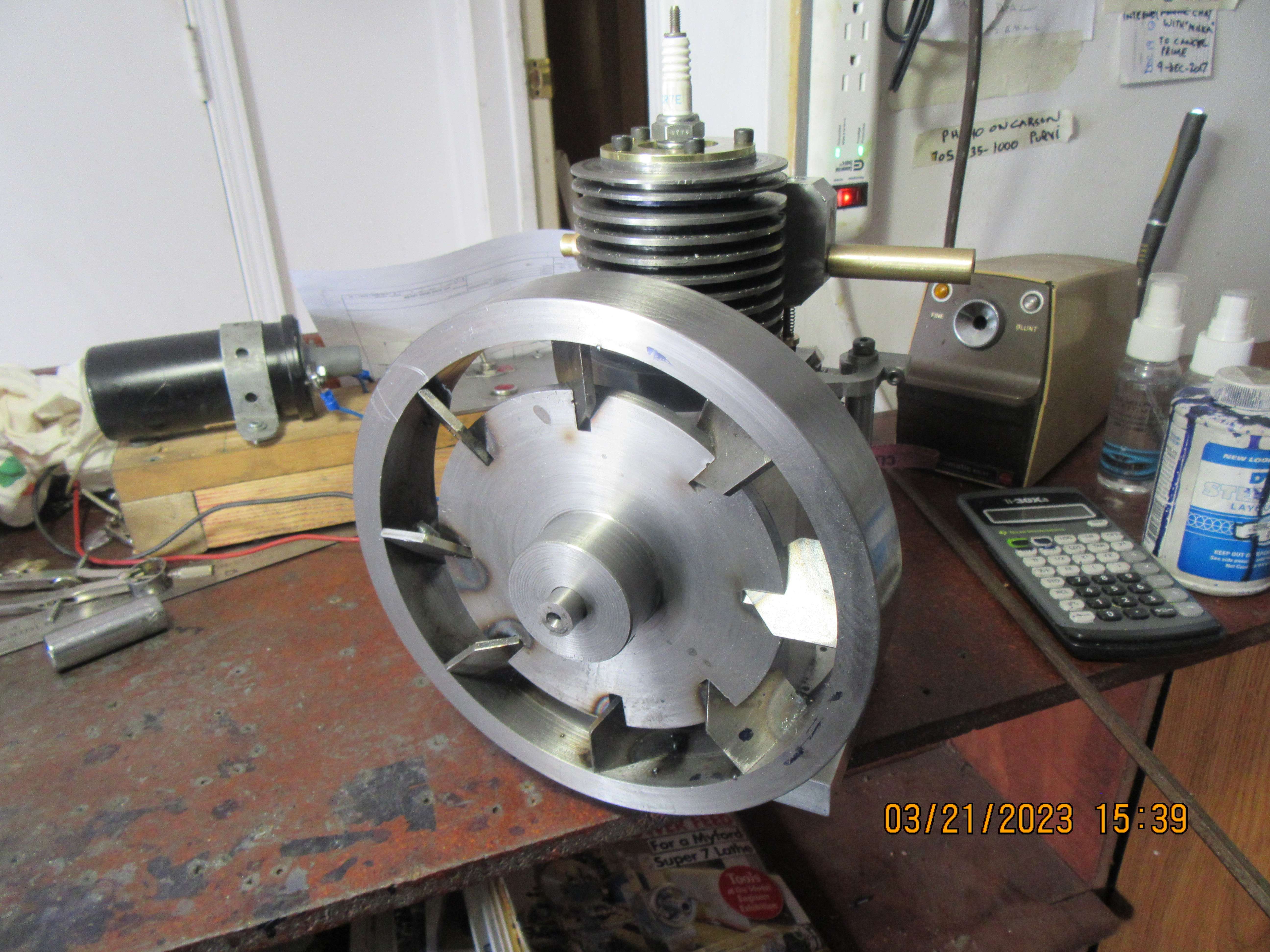
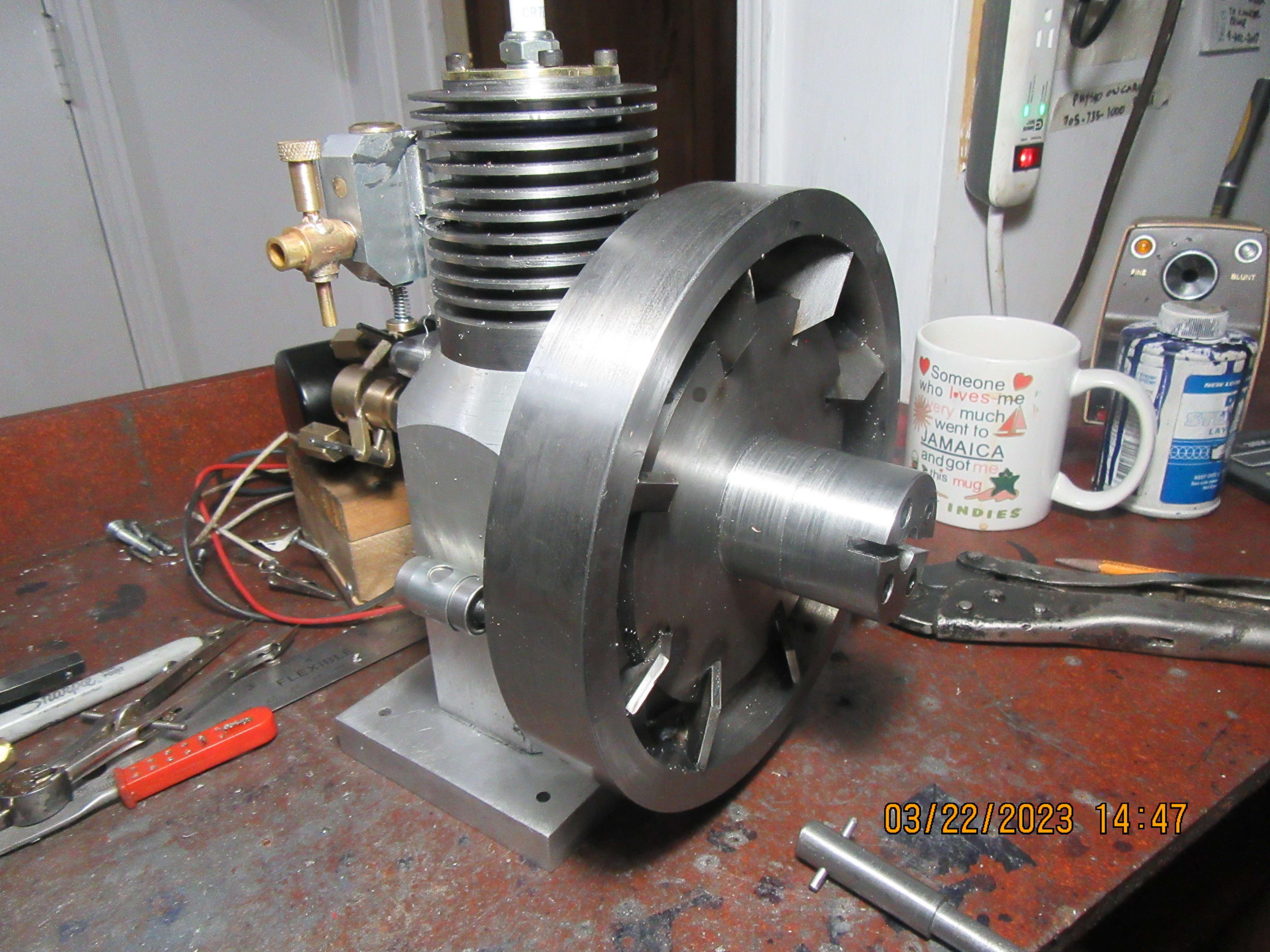
Great deeds were accomplished today. Ignition points and condenser were ordered and can be picked up tomorrow. New sparkplug was purchased and installed. New Viton piston ring and head gasket o-rings were picked up and installed. Finally made a new longer keyway bushing and was able to use it with my broach set to cut a keyway in the flywheel hub. (These broaches cost $100 each and will break if the keyway bushing is shorter than the hub being keyseated.---Don't ask me how I know!!) The keyway was cut in the crankshaft. There are some really nasty looking mig welds on the side of that flywheel that faces the engine, I will grind them down before I am finished here. So--For the moment everything is assembled, first time. I still have gaskets to make, add oil ports to the crankcase, and welds to grind. I also have to make a starter hub that attaches to the flywheel so I can use my electric drill as a starter.
OxfoZ9.jpg

RVSBzl.jpg

mbREYb.jpg
 
Today I machined the starter hub which attaches to the flywheel and mounted it. Likewise machined the part which fits into my electric drill. I picked up the points and condenser and installed them. The two brass plugs that fit into the manifold above the valves were polished and then loctited into place. I still have to put in an oil filler pipe---haven't thought about it too much, but I've almost ran out of things to make.
cYElX9.jpg
 
So, what did I do today?--I made and installed the gasket which goes between the manifold and the cylinder---the gasket that goes between the cylinder and the crankcase, and the gasket that goes between the crankcase and the baseplate. All from 0.030" waterpump gasket material from my local auto shop. I drilled and tapped the crankcase for a 1/4"-npt pipe plug, which according to various calculations and measurements will give me an oil level that comes up 0.125" on the bottom of the connecting rod at the very bottom of the piston stroke. I set the ignition timing. I set the valve timing. I flame hardened and quenched the cam and the cam follower wheel which were both made from 01 steel. I soldered the needle into the brass cap which adjusts the needle on the carburetor. I tested the carburetor to make sure that when air flowed thru the main body, it would create enough suction due to venturi effect to lift fluid from a tank mounted below the carburetor. I wired up the ignition points and condenser. I set the valve lash on the exhaust valve. I stopped at my fastener supplier and purchased a 0.013" wire diameter compression spring to be used on the atmospheric intake valve. What do I have left to do?--Fill the crankcase with oil and file the notch in the swing arm which the hit and miss mechanism latches into to hold the exhaust valve open during the miss cycles. I have to select and install a tension spring between the governor arms. Then maybe I'll try and start this engine!!!
 
Today was a first try to run the engine. No go---no firing. Time for diagnostics. Pulled off the manifold, made up a blanking plate to cover the holes in the side of the cylinder, then bolted the blanking plate back on with a gasket. Pulled off the cylinder head and stuck my thumb over the top of the cylinder. When I did this and flipped the flywheel over, the engine would "bounce back" from compression. Tried it again with a layer of oil over top of the piston--engine bounced back , but not enough difference to indicate a piston ring not sealing. Took a good look at the o-ring head gasket and determined that it hadn't been flattened equally all around. Sometimes this happens if the head bolts are too long---they bottom out in the cylinder before they really squeeze the head gasket properly for a good seal. Shortened up the cylinder head bolts and retorqued them evenly, ensuring a definite seal at the head gasket. Removed two coils from the intake valve spring. This is a really delicate dance on an atmospheric valve. You need enough spring pressure to close the valve, but not so much pressure that the spring overcomes the atmospheric pressure which opens the valve. Will try again tomorrow, after rechecking valve and ignition timing. I have a can of ether which can be a good thing to convince the engine to fire. Once the engine fires a couple of dozen times, the valves seal much better. My theory on this is that the steel valve deforms the brass valve seats enough to give a much better seal.
 
The flywheel fan seems to put out a good quantity of air, but something isn't quite right. The engine fires and runs but eventually it runs down and stops. None of the firing strokes are very powerful sounding, and the engine doesn't have proper compression. I'm quite sure that the valves are not leaking. I'm suspicious of the piston ring. Tomorrow I will pull the piston and change the Viton ring. It may have been damaged when it went down past the ports in the side of the cylinder when I installed it.
 
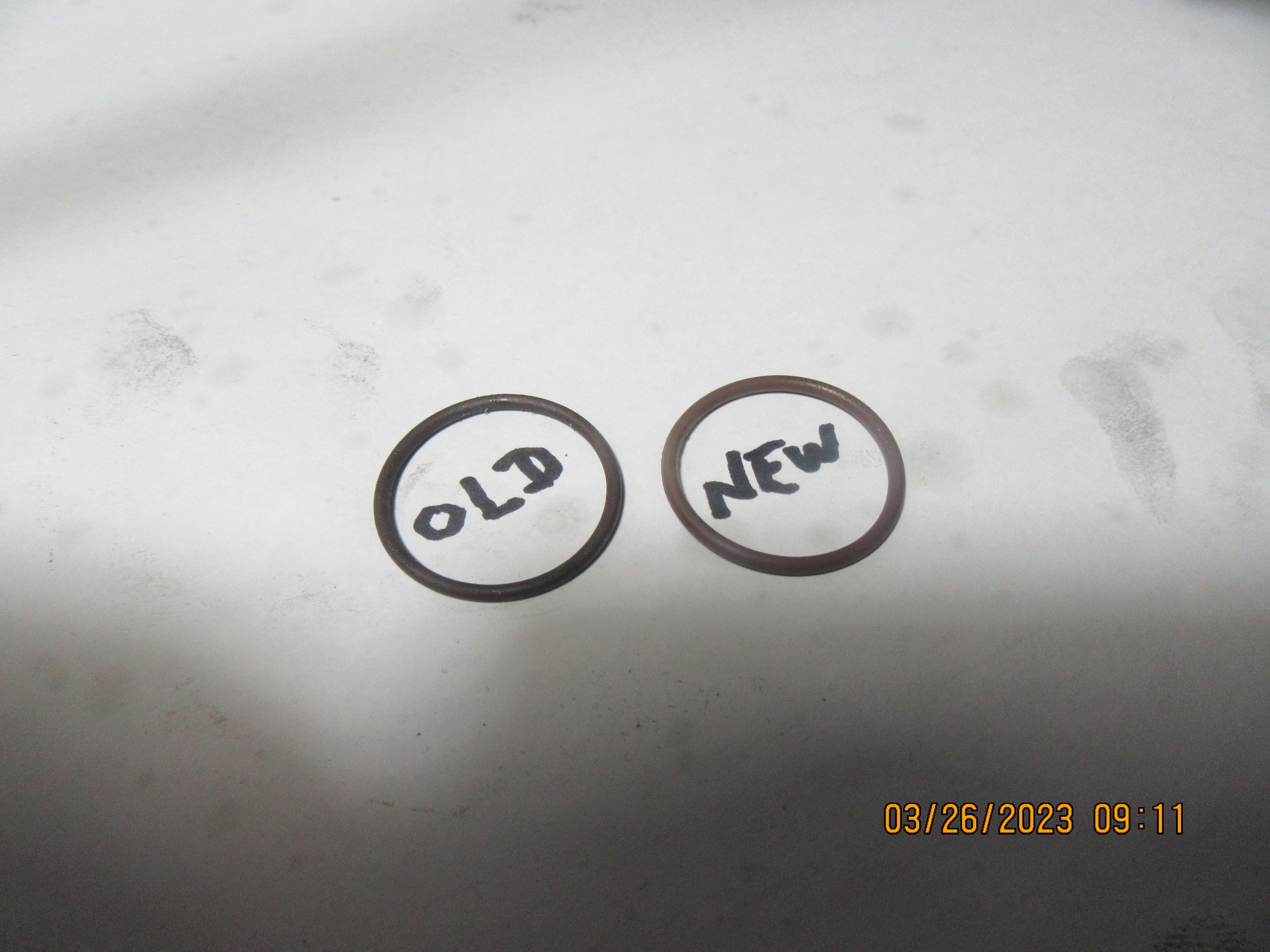
I don't know how well you can see this, but---the ring that was used to break in and get the initial runs on the engine is on the left. A visual inspection of it doesn't show any cuts or missing pieces from going past the ports in the cylinder when the piston and ring were installed. The ring on the right is a brand new, never installed viton ring. It appears to be larger in cross section than the original ring. Measurement with a vernier caliper shows that the new ring has a cross section of 0.072". The "old" ring has a cross section that measures "0.063" cross section. The only thing that I can think of is that I had reamed the i.d. of the cast iron cylinder, but not honed it. The roughness left from the reaming operation has worn away the outside of the ring, and thats what happened to my compression. Later today I will install the piston with the new ring on it and see how that affects my compression.
7NhYkZ.jpg
 
Hi Brian, when you linish cast iron bores for using Viton O-rings, what is the finest paste/abrasive that you use? - I was involved with the materials Lab at work, where they polished sections of all sorts of materials to get mirror finishes on almost anything, so the sections could be scutinised under the microscope. The last polishing compound (of about 10) was a very expensive fluid containing diamond dust - applied by aerosol! - I imagine that would produce a surface suitable for O-rings, like the ground bores of hydraulic brake cylinders, etc. (car/lorry drum-brakes have good polished cast-iron hydraulic cylinders that can make good steam engine cylinders. - My Dad used them!).
Cheers,
K2
 

Latest posts

Back
Top