V8 Ignition

Home Model Engine Machinist Forum

Help Support Home Model Engine Machinist Forum:

This site may earn a commission from merchant affiliate links, including eBay, Amazon, and others.
stevehuckss396 said:
The problem with that is they are way to big. In the case of a V4 the trigger has to be in the distributor to fire correctly.

What is the smallest photo/sensor pair you know of?
They are available in surface mount discrete components, I am looking at a detector approx 5x6x1 mm. You dont have to buy a pair already mounted, you can buy them seperately.
 
Hey Jim,
Is there any way we could see how you have your components arranged inside that small distributor?
gbritnell
 
jpeter said:
My test show that at 2500rpm the coil completely charges in .25ms and then dwells at full charge for close to 2 more ms. Taking these facts into consideration I have no trouble believeing I could increase the rpm by a factor of 7 and still be spark'n the plugs. That's 17000 rpm. I think most would be happy with that.
From my poor memory I believe some operational problems begin to show up with the square of the speed, but my memory is not always to be trusted. :) I look forward to doing some testing when I get my scope back.
I have the entire hall effect unit; magnet, sensor, shutter for switching and zeners for protection, rotor and cap built into a 1 inch outside diameter distributor. The electronics board is in the base, under the engine. Regarding the schmidt trigger, the rise time of the hall switch is pretty fast and clean. My scope shows the addition of a schmidt trigger would be of little value.

Thats great if you dont need it, but be sure of your testing. Every wire is an inductor, and under normal operating conditions I see some pretty crappy signals. Some hall effect sensors may already include the schmidt trigger on die.

I switch the hall effect sensor with a steel shutter.

Thats great, that is how the auto companies do it.
I'm not sure how switching with multiple magnets would work cuz with the small size of the distributor the 8 magnet style cam didn't work; the magnet interfered with each other too much.
I have heard others complaining about the same thing, as well as induced voltage from flying magnets.
 
With such small distributors, I would think that optical sensors work better. They could be of the reflector type that's no bigger then a 4x4x4mm cube. The sensor can be a disk painted black and white or a little "star" of metal with reflective coating.
 
For a four cylinder, you only need to drill two holes at 90 degrees through the distributor shaft. For an 8 cylinder, you can use two pickups with that same simple setup. Which kind of brings me to another pet peeve of mine. At our scales, and with no real structural load, we should probably make our distributors, and especially the shaft, entirely out of plastic
 
Hi Jeff,
You lost me on your last post. Make the distributors and especially the shaft out of plastic? With such small diameter shafts the plastic would twist off in no time not to mention the heat issues. You could make the body out of plastic but then if you had to tap any holes in it the holding power of the threads would be very marginal.
By following this thread it looks like there are a few different trains of thought on ignitions for miniature engines, some viable and some not. As far as I can tell from a packaging standpoint (overall size) there's only 2 options out there, one is the Jerry Howell ignition (I see they have new coils available but very pricey) and the other is the S&S ignition. At this point for the money and performance I don't think you can beat the S&S. I have 2 of them, one with the voltage reducer for operating from either a 6 or 12 volt battery, and one working from 4 AA Nimh batteries. I have had very good performance from them and Roy Scholl is great to work with.
When someone else comes up with something better, size, cost, simplicity and operation I would be more than willing to listen.
gbritnell
 
Hi George,

I guess we may have different visions of what the distributor shaft would turn. A spring and carbon button from the center of a cap to a thin brass strip for a rotor would not necessarily provide much of a load, even for nylon. There are a bunch of strong machinable plastics around now. I don't have any particular design in mind, but when we scale a distributor but cannot scale the electricity, non-conductive materials should be a great benefit.

These days, even intake manifolds are plastic, if distributors were still used, I am sure they would have gone plastic long ago. Weight, cost, and heat dissipation all improve with plastic for the automakers.
 
jpeter - thanks for your measurements. I'm a bit intrigued that your circuit actually works better than the theory suggest and glad on your behalf ;)

As to your to your thoughts about changing the dwell time - I wouldn't .... but then again - I would like to rev that wonderful engine of your out quite a bit more than you do in the video ;D Certainly NOT to the point of destruction, but open 'er up all the way for some 5-10 seconds at a time ;)

In a modern ignition you have a processor and a knowledge about where the crank is in degrees - or at least fractions of the rotation. My Suzuki DL 650 has a 24 tooth gear with two neighboring teeth removed "read" by a coil. That gives a 360/24 resolution of the crank rotation and direct indication of the sync info (the missing teeth) in one durable sensor. Since the system knows where the crank is in regard to ignition point and how long time there is to firing, it also knows when to turn on the ignition coil current so the coil only just reach max current before it's cut off again => minimum current consumption and maximum reliability in as little heating of the components as possible.

I'm sorry but I'm really busy in RL right now, so I haven't found time to draw a complete circuit.

On a simple system you have a resistor in series with the coil and use a coil for a lower voltage than you have available. This give you a system that will be up to max current in a short amount of time => Higher revs and still do not burn the coil.
 
Hi

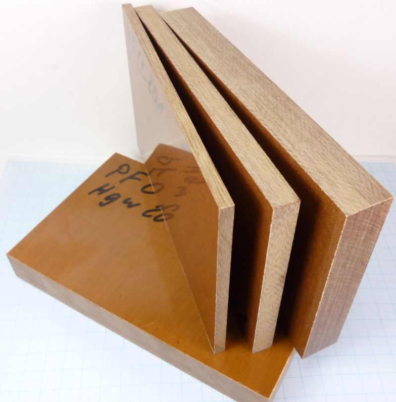
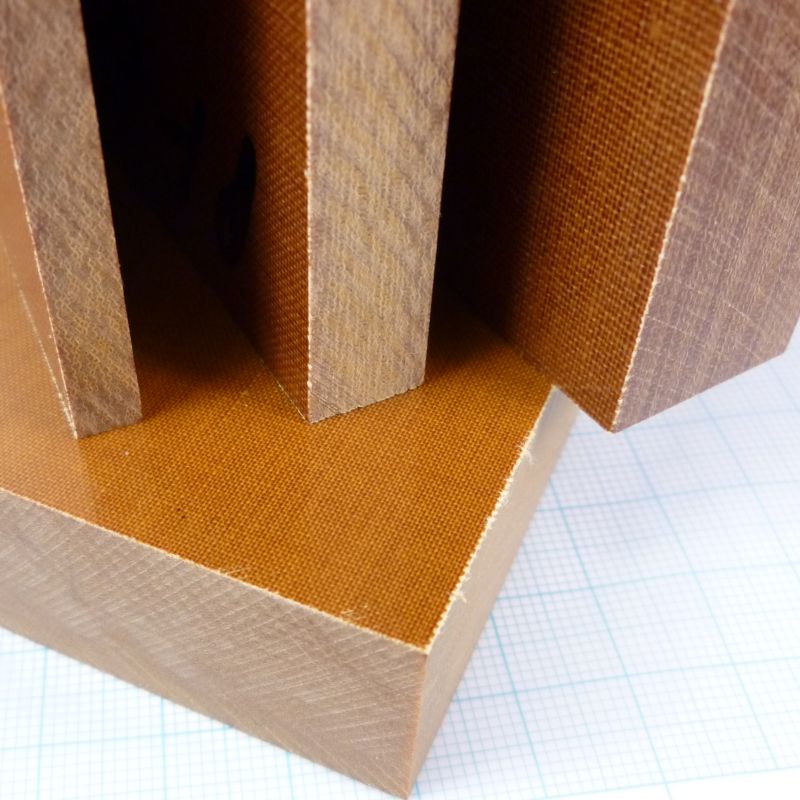
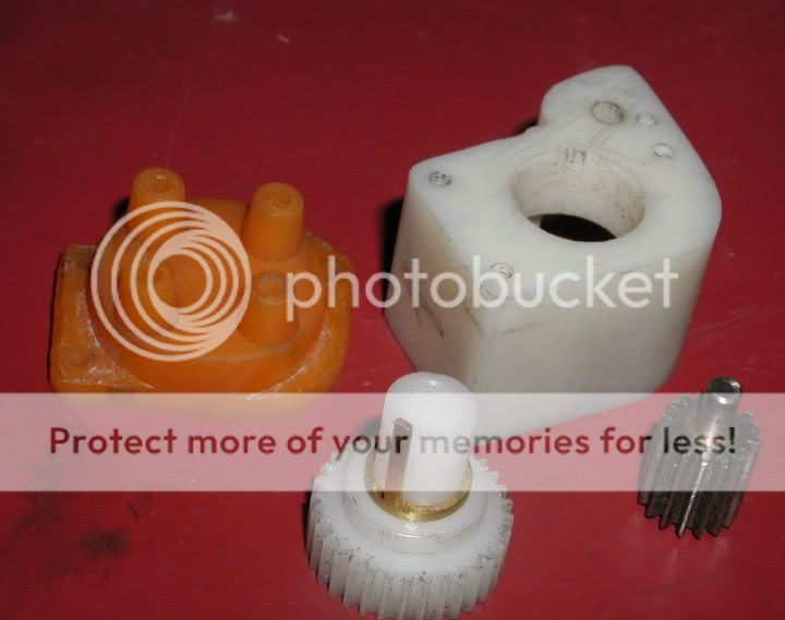
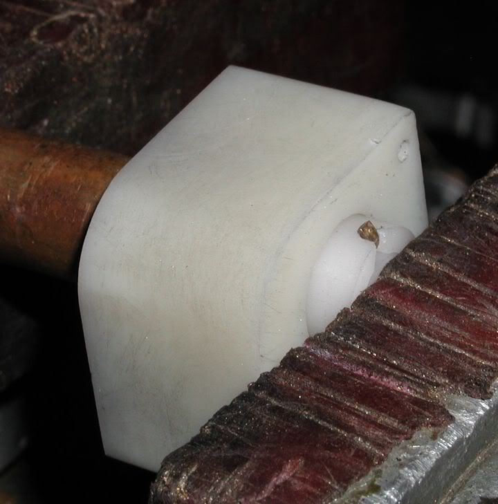
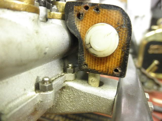
I believe in contrast to thermo plastics like POM (Polyacetal) or Nylon (Polyamid) etc. a Duro Plast material like laminated fabric should be more convenient for the parts of a small distributor.

This stuff is made of linen fabric soaked with phenol resin, nice to machine, a very good isolator and thermally resistant enough for our demands. And you can tap even miniature threads very well. I believe I will build my next ignition housing from this material


HGW_01.jpg


HGW_02.jpg


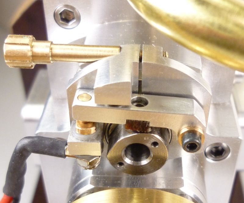
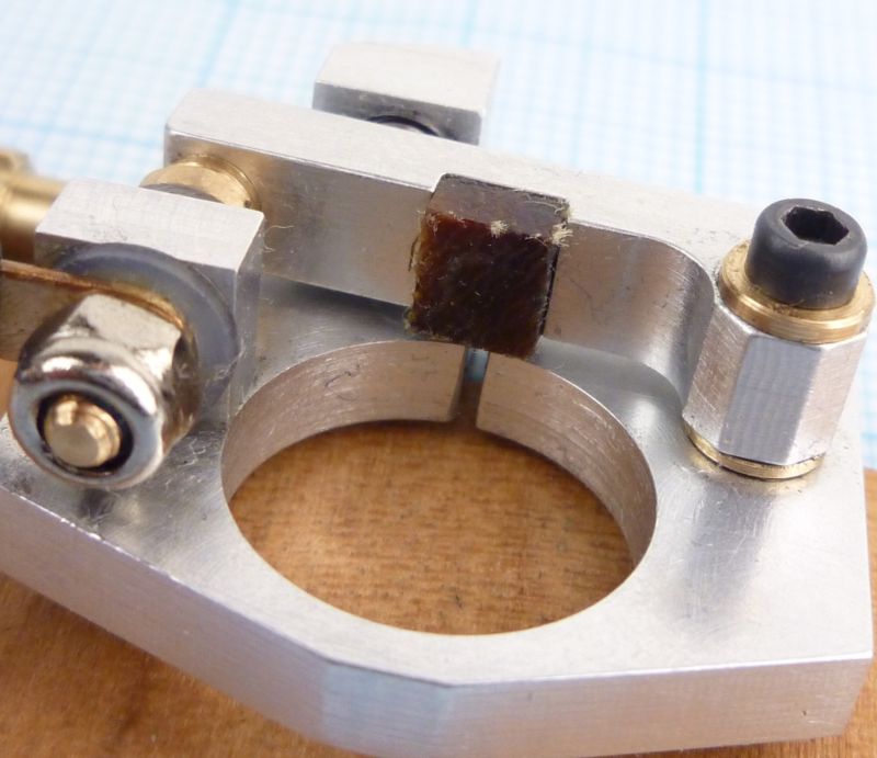
And this material has very good wear characteristics too. I made the cam follower of my ignition lever from this duroplast, after several hours of running you can hardly see any structural change on the contact surface.


SLVE_VER1_1031.JPG


SLVE_VER1_1033.JPG


Achim
 
Made a distributor (fake magneto) using a plastic like nylon for a rotor with shaft and put inside a plastic housing. This worked good for less then an hour. Then failure from too much friction between the materials even though greased with a silicone grease.

Mag-Distparts.jpg

Rotorbentout.jpg


Replaced the plastic housing with phenolic laminate (Micarta) and now the Nylon rotor shaft gets along good with the Micarta housing.
Phynolicbody.jpg


For "points" use 2 magnets 180 degrees apart in flywheel with hall sensor. This works good for a 4 cylinder 4 cycle engine. Don't see why 4 magnets 90 degrees apart wouldn't work for a 8 cylinder 4 cycle engine.

Gary
 
stevehuckss396 said:
I have been considering what to use for an ignition system for the small V8. Roy's module will only yield 12,000 sparks per minute.
Is there another module out there that will supply spark at that rate, or am I going to have to build my own.

There is one in Strictly IC I think it's issue No55 Page 5. Claimed to produce around 54000 sparks per minute.
However that's not the one I built. I made the one detailed in Model Engineer July 2004. I've tested it to over 50000 sparks per minute on the bench using an Automotive coil and the hall sensor activated by a 32 tooth spur gear running on a electric drill right from dead slow through to 1600 rpm = 51200 sparks/minute. I guess it would be out of order to scan the Model Engineer article and put it on here?
Nick
 
nj111 said:
over 50000 sparks per minute on the bench using an Automotive coil and the hall sensor activated by a 32 tooth spur gear

Hello Nick.

How does a hall sensor fire off of a gear tooth? Is the gear magnetized? If that is the case why don't we machine up an 8 toothed thingy just like in the MSD distributor.
 
stevehuckss396 said:
Hello Nick.

How does a hall sensor fire off of a gear tooth? Is the gear magnetized? If that is the case why don't we machine up an 8 toothed thingy just like in the MSD distributor.

You mount the magnet behind or just aside the sensor, and when the tooth cuts into the magnetic field, the sensor trips on the bending of the field across its face. Takes some rather precise positioning, and you cant have other magnetic materials nearby, but thats how many automotive sensors work.

Joachim Steinke said:
I believe in contrast to thermo plastics like POM (Polyacetal) or Nylon (Polyamid) etc. a Duro Plast material like laminated fabric should be more convenient for the parts of a small distributor.

Thats one of the materials I had in mind. Its (probably) a slightly more modern version of bakelite and goes by the trade name Garolite at McMaster Carr, here in the US. I use that a lot in transmitting antennas as its a very good high voltage insulator.
 
stevehuckss396 said:
Hello Nick.

How does a hall sensor fire off of a gear tooth? Is the gear magnetized? If that is the case why don't we machine up an 8 toothed thingy just like in the MSD distributor.

Hall effect devices are sensitive to a change in magnetic flux, so to avoid attaching a magnet to a rotating shaft it is simpler to epoxy a magnet to the back of the hall device and let the presence of ferrous metal at the face act as a flux concentrator. This can be a slotted disc. I'll try to PM you some more info. Nick
 
You can buy a hall effect sensor with a built in magnet. It's called a gear tooth sensor.
 
jpeter said:
You can buy a hall effect sensor with a built in magnet. It's called a gear tooth sensor.

That's not a hall sensor, it's a pickup coil. They are used in diesel engines to check the speed for the governor.
 
Noitoen said:
That's not a hall sensor, it's a pickup coil. They are used in diesel engines to check the speed for the governor.

If these devices switch as fast and require no external magnet, Why are we not using these instead of hall sensors. Seems to me it would be easy to mill up a disk into something with 8 points. Could steel be used or is iron (cast) better.

This could change the way we fire our engines. Things just got smaller.
 
stevehuckss396 said:
If these devices switch as fast and require no external magnet, Why are we not using these instead of hall sensors. Seems to me it would be easy to mill up a disk into something with 8 points. Could steel be used or is iron (cast) better.

This could change the way we fire our engines. Things just got smaller.

Lakc said:
Takes some rather precise positioning, and you cant have other magnetic materials nearby, but thats how many automotive sensors work.

Those are the basic problems involved. In full size practice they measure the tip of helical gears, but approx 4mod size. In window type openings they seem to design 10mm clearance for the gaps. Suitabily large enough windows and your loosing the scale factor but it can be made more compact if your willing to fiddle with it. Even in full size, we occasionally have problems with proper gap and clearance changes due to temperature.
Personally, I would still lean towards optical if I had to re-engineer it.
 

Latest posts

Back
Top