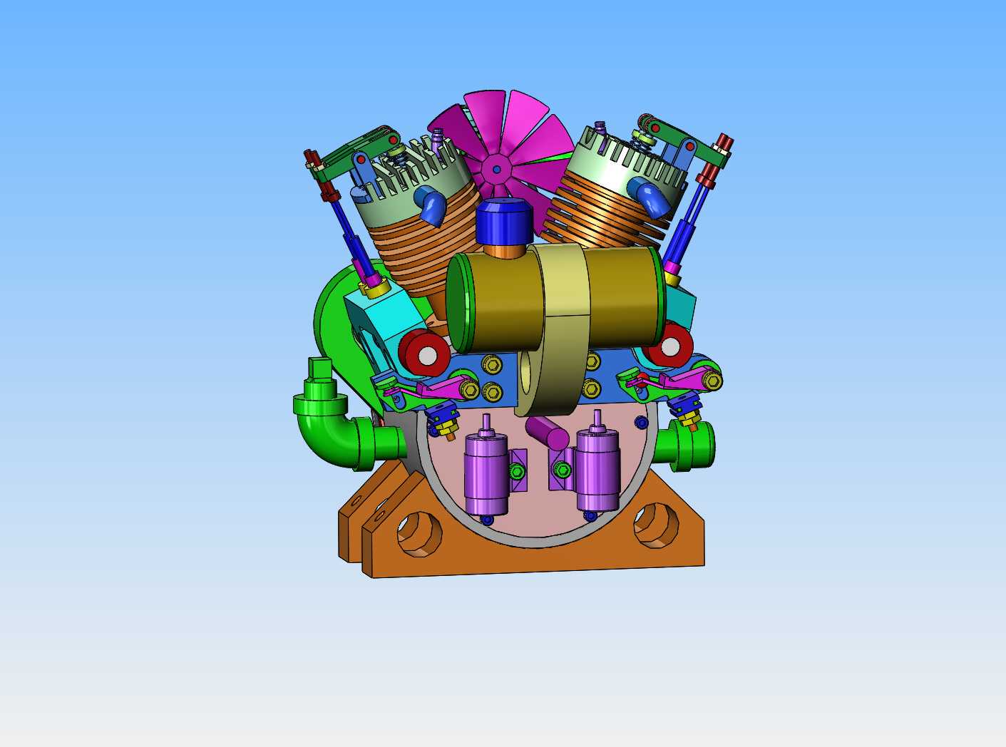
V-TWIN---MAYBE V-4

Home Model Engine Machinist Forum

Help Support Home Model Engine Machinist Forum:

This site may earn a commission from merchant affiliate links, including eBay, Amazon, and others.
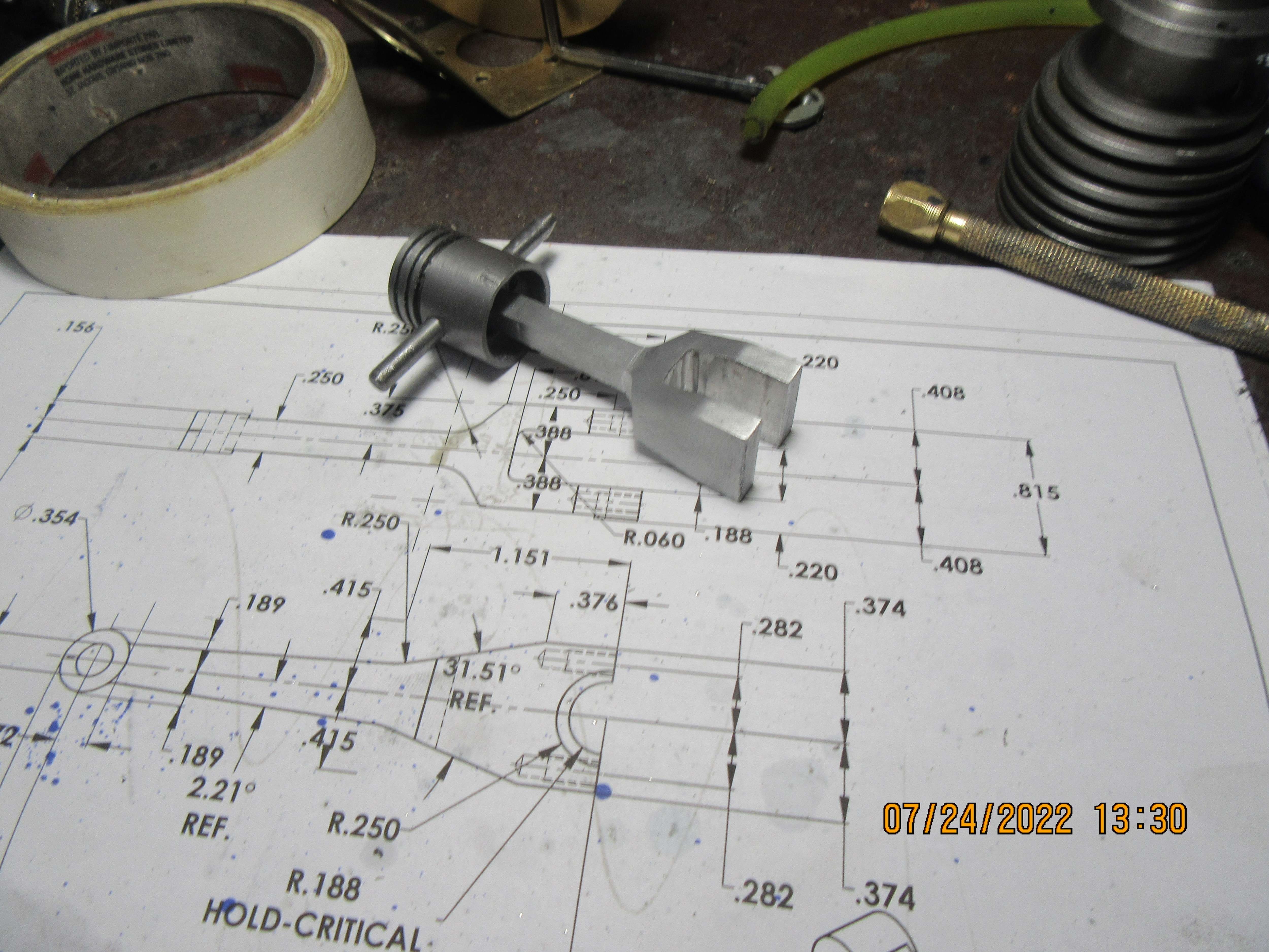
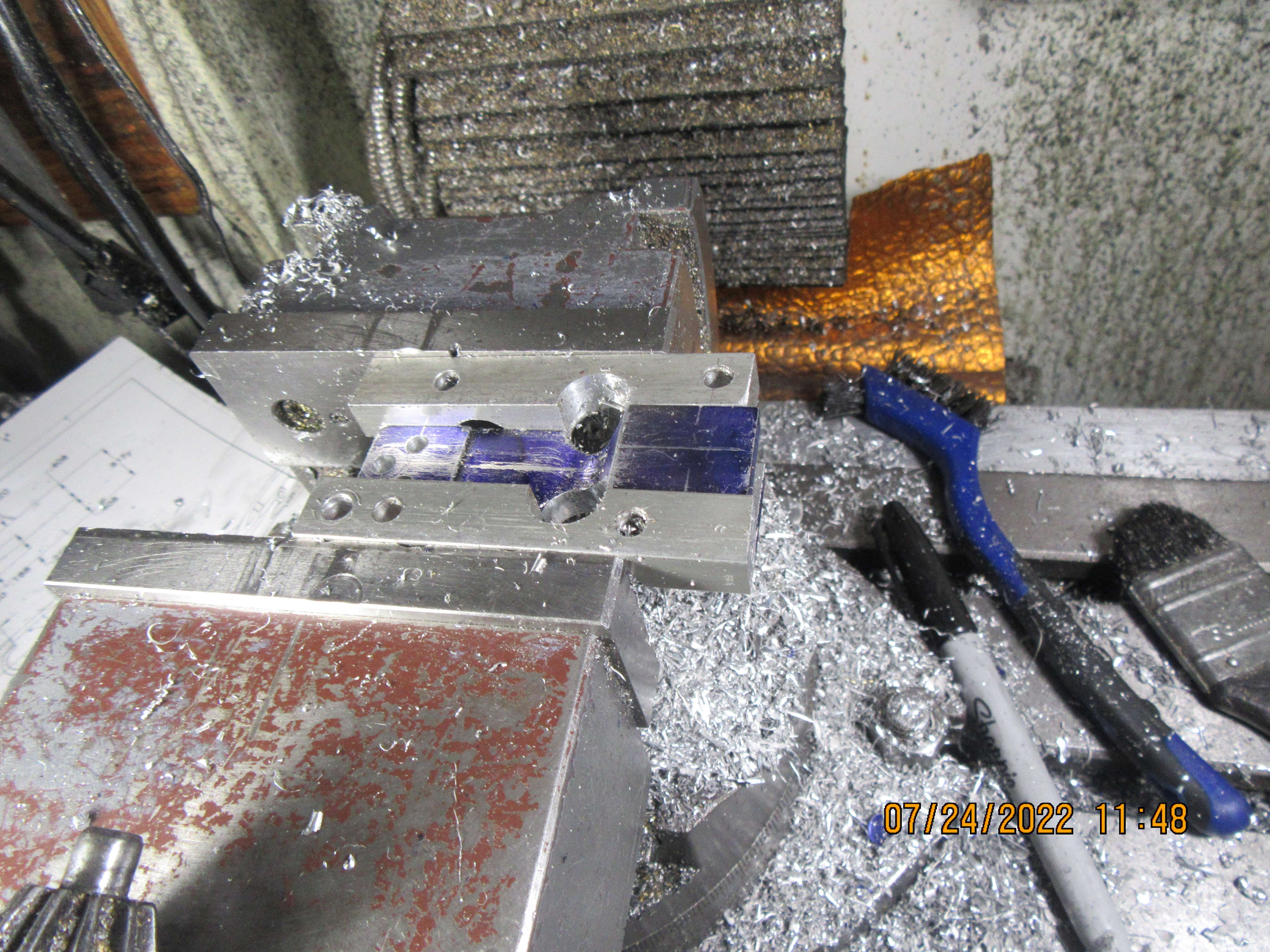
Now we turn the material 90 degrees and machine the second side. Once again the 1/2" diameter holes where the con rod begins to narrow will fall partly outside the con rod material, so once again we have a piece of scrap aluminum clamped on both sides of the con-rod so as not to drill holes thru my vice jaws. The 3/16" wrist pin hole has been drilled and reamed, and two smaller holes which form the radius tangent to the sides of the con rod have been drilled. The hole for the crankshaft journal will not be put in until the con rod caps are finished and installed.
Xm9brh.jpg
 
Hi Brian,
I see on the drawing there is a radius on the inside corner of the slot to make the fork. What size do you use? I was involved in a design job in the early 80s, where we cured "stress fractures" with changing the radius from 1 mm to >3mm - as even 2.5 mm could be failed after enough cycles. But we ran out of "life" for testing the 3mm radii corners. - In fact to help the plant we specified 1/8in cutters to generate the corners. (They had surplus imperial tooling!). But the major issue was getting a clean smooth transition from radiused corner to flat face. Then all our troubles disappeared...
Cheers! - Your work is just excellent. Thanks for the tutorials!
K2
 
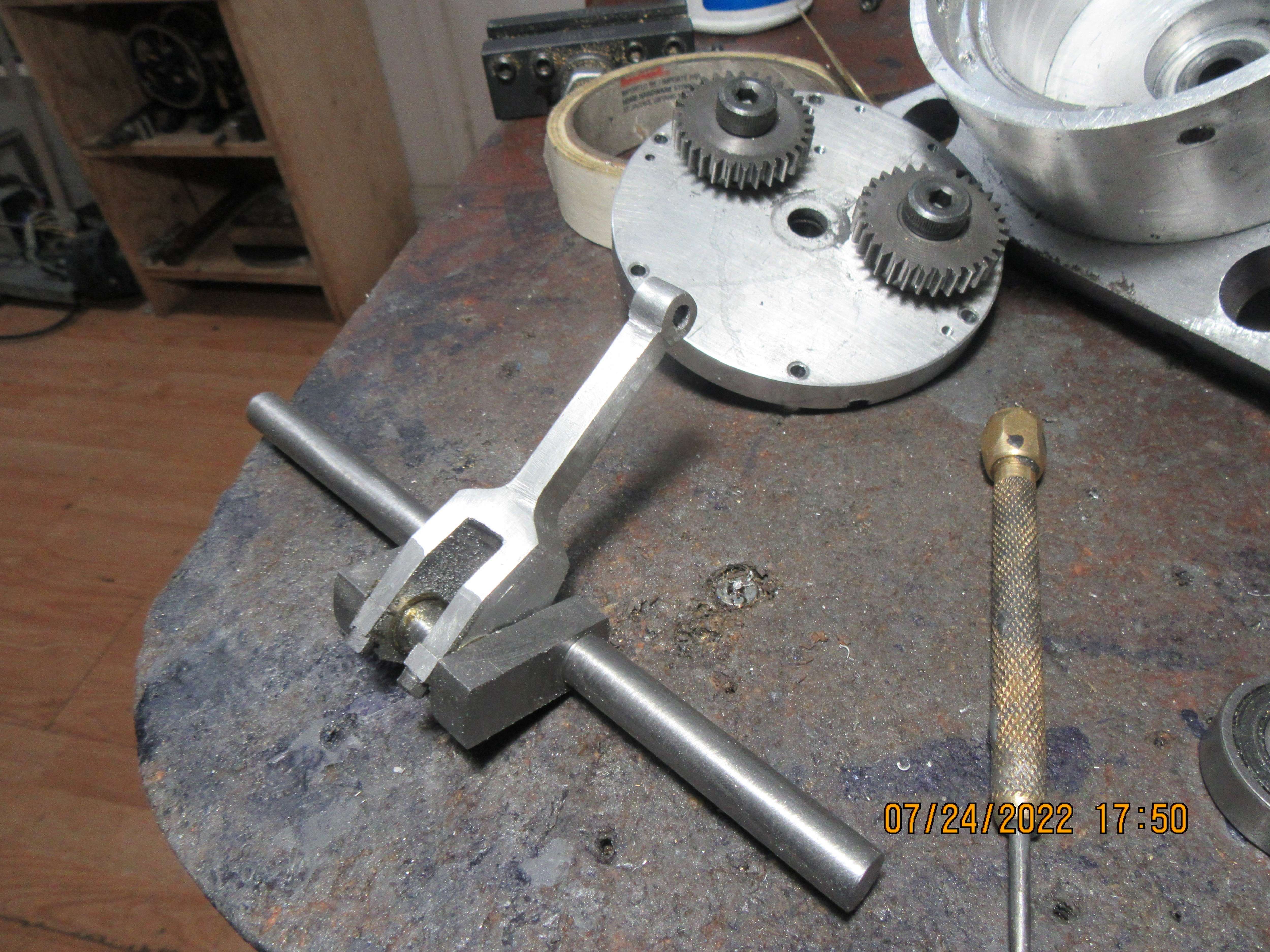
And here we are--This con rod is almost finished. I still have to drill and tap four holes in the big end for the con rod cap bolts. I started this morning at 7:00 and it's 2:00 now. take out an hour for breakfast and lunch, and there's still 6 hours work in this con rod. I might get the caps done this afternoon if I don't take a lazy spell.
t6pvbe.jpg
 
Steamchick--you've caught me out on something that few people notice. When I make these component details, I do so blindingly fast. Then, days later, when I go to actually machine the part, it is common to find that I have left a dimension off the drawing. That's okay, it only takes me seconds to add the dimension, because the math data has all been entered when I designed the 3D cad model. Knowing that I will probably sell a few sets of the plans to builders around the world, I add the missing dimensions as I discover them. I can do this with my software, but people who buy plan sets from me can't because they receive .pdf files, not my original Solidworks files. My cad program costs about $7000, which was a legitimate write off for me and my business, Rupnow Machine and Automation Design. No one building small engines as a hobby wants to eat that kind of cost, so the drawings are sent out as pdf files, and anybody can open them.---The rad is 0.060".
 
So, the fork style con rod is finished and so are the two rod caps it requires, and bolted in place on the crankshaft. There is a full 8 hours in this con rod and caps, and I'm quite happy with the way they turned out. Tomorrow I will tackle the knife style con rod that rides on the same journal and fits inside the slot in the fork style con rod.
V2PYLx.jpg
 
---I won't really know for sure until tomorrow, but I may have to cut an access hole in the bottom of the crank case, to tighten the rod caps onto the rods. Things are starting to get very crowded in there. Trying to install and tighten con rod cap bolts when you can only swing the allen wrench in a 25 degree arc is kind of like banging your head against the wall.
 
Hi Brian, Thanks for that reply #144. I wasn't "catching you out" in any way for a missing dimension, though I'm sure it will be on the plans when published. I was simply curious, but professionally impressed that you had considered this and added a stress relieving radius. To few think of these things, that are second nature to professionals. But to anyone making your design these things are also very important to follow. I guess you simply had the radius on the milling cutter that milled the slot? - Milling from the "Big-end" of the conrod? - Too many would have used a sharp-cornered cutter, perhaps to their demise?
Well done and thanks for the reply.
K2
 
Would it be possible to assemble the rods on the crankshaft, slip the bearing onto the crank, slip the crank into the case and get the rods up through the cylinder holes, then align the crankshaft and insert the bearing into the case?
 
Brian
How are you going to control the side to side play between the blade rod and the fork rod. We used a very similar set-up on EMD engines. Only there is a slot machines into the inner radius of the fork rod that the machined edge of the blade rod rides in. Then the fork rod is a basket design that bolts to the sides of the fork rod. Then the rod brgs are pegged to the fork rod. So that the rod brg rotates with the fork on the crank pin. And the blade rod rides on rod brg. When I get home tonight from work I’ll send some pics that will explain it better
Thanks Tom
 
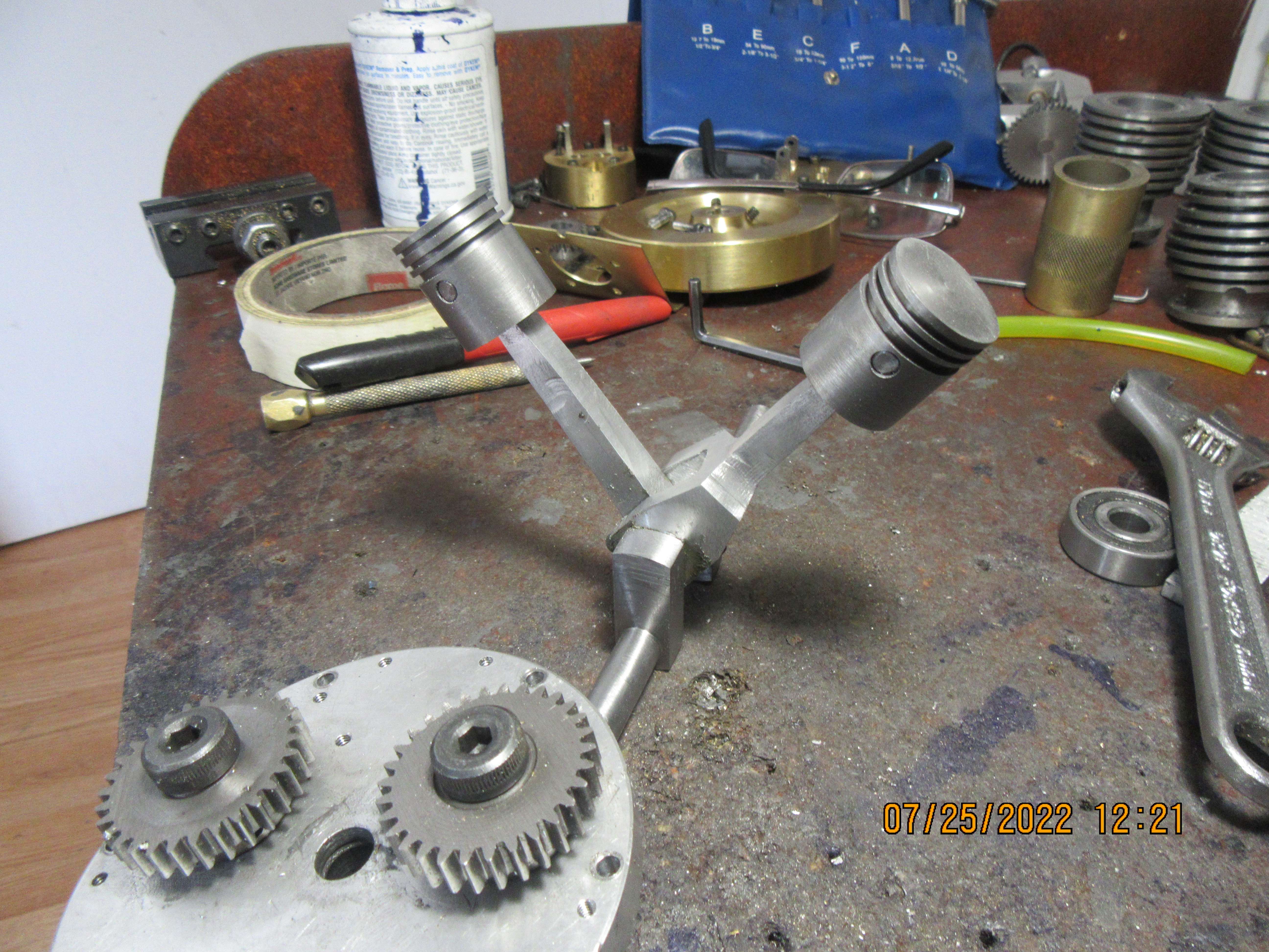
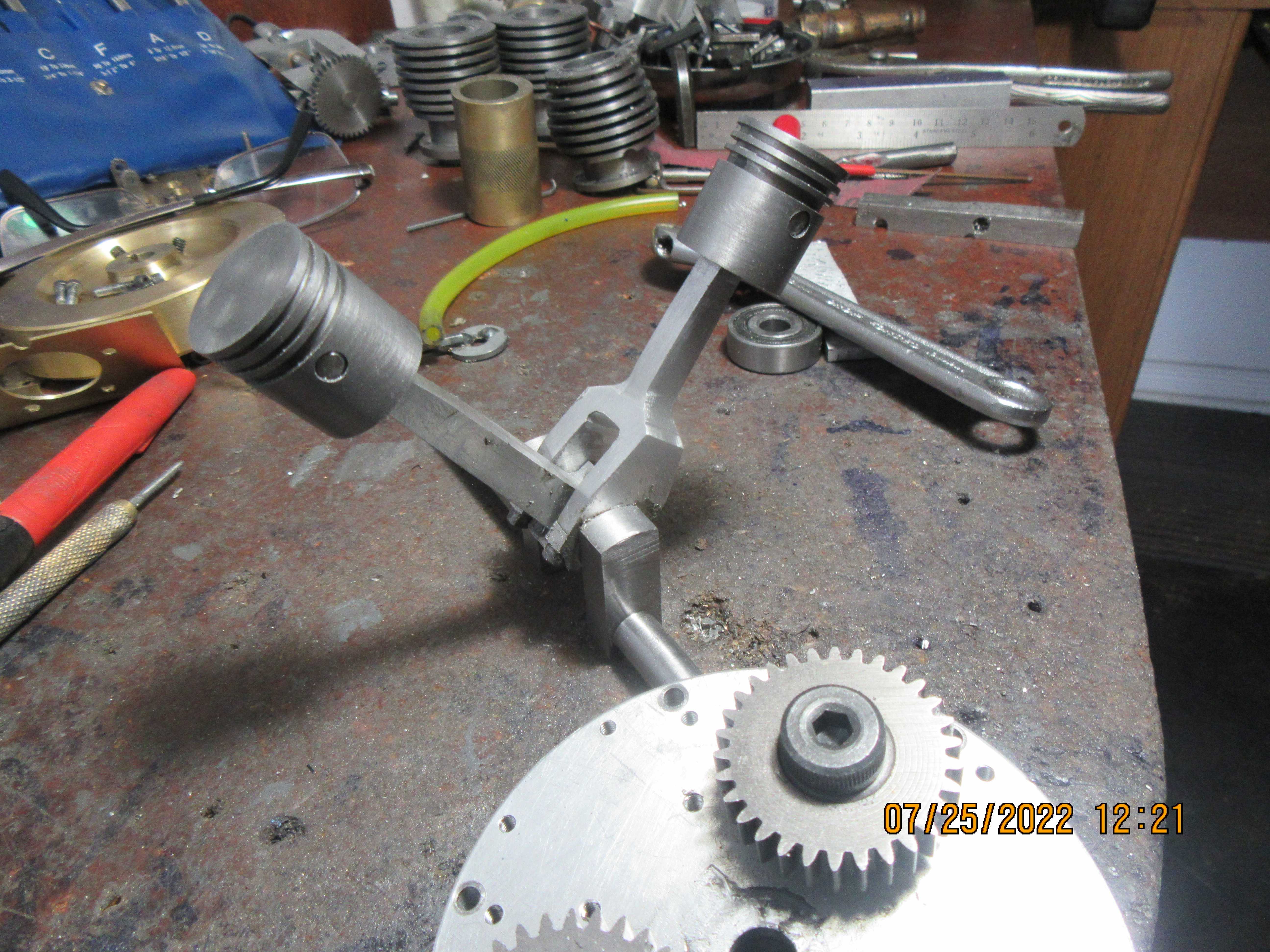
Now this is a beautiful thing!! The second con rod and cap took only three hours to make, and an hours fussing and fitting to get crank, rods, rod caps and pistons to all go together nicely. I'm liking it!!!
cdgRMV.jpg

TdUUIn.jpg
 
Stephenhuckss----I thought you might be onto something there with your suggestion, but no such luck. (I just tried doing it). I'll put an access hole in the bottom of the crankcase. I don't have any large taps so my access hole will have to have a cover that bolts on with perimeter bolts.
 
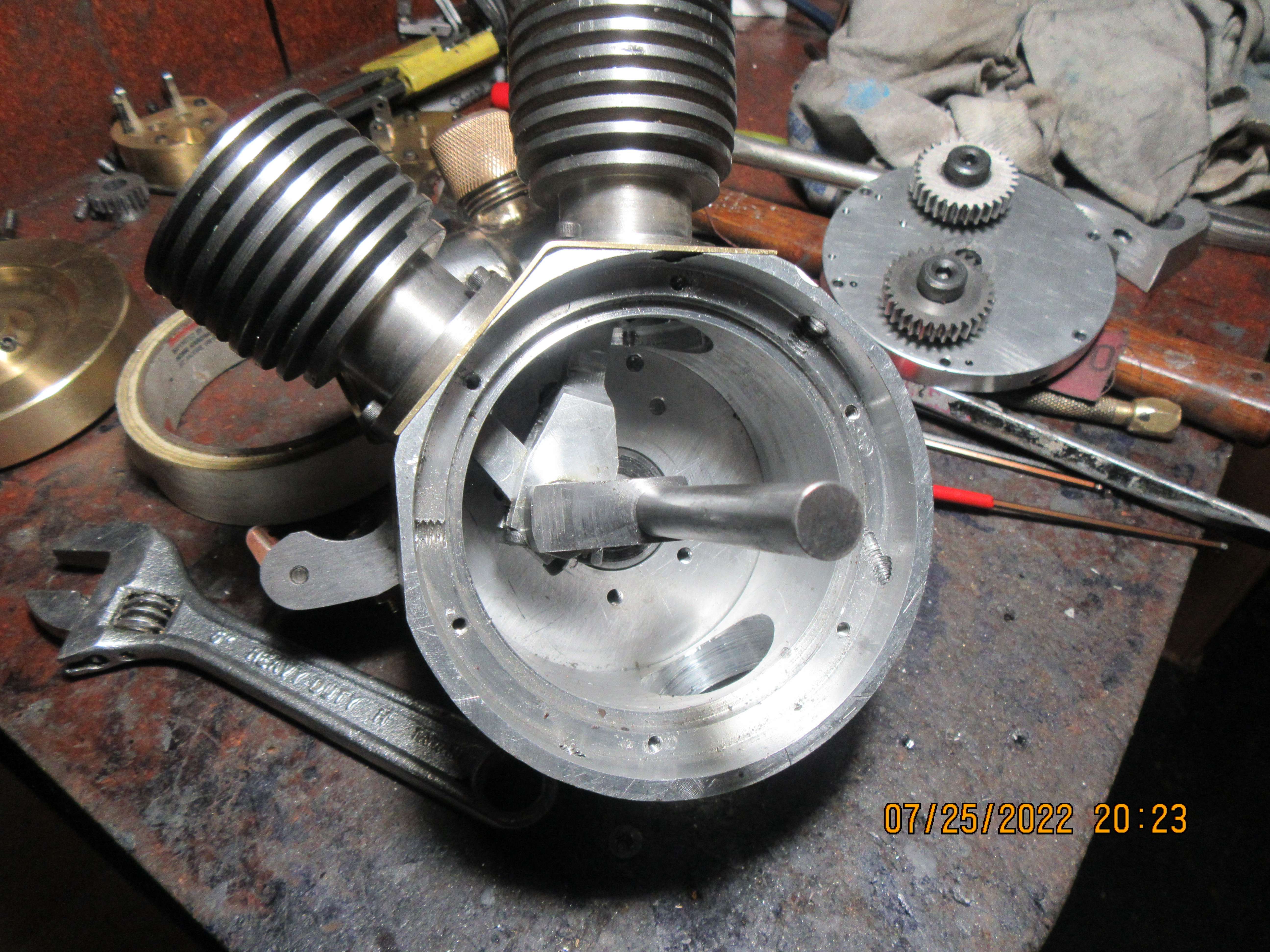
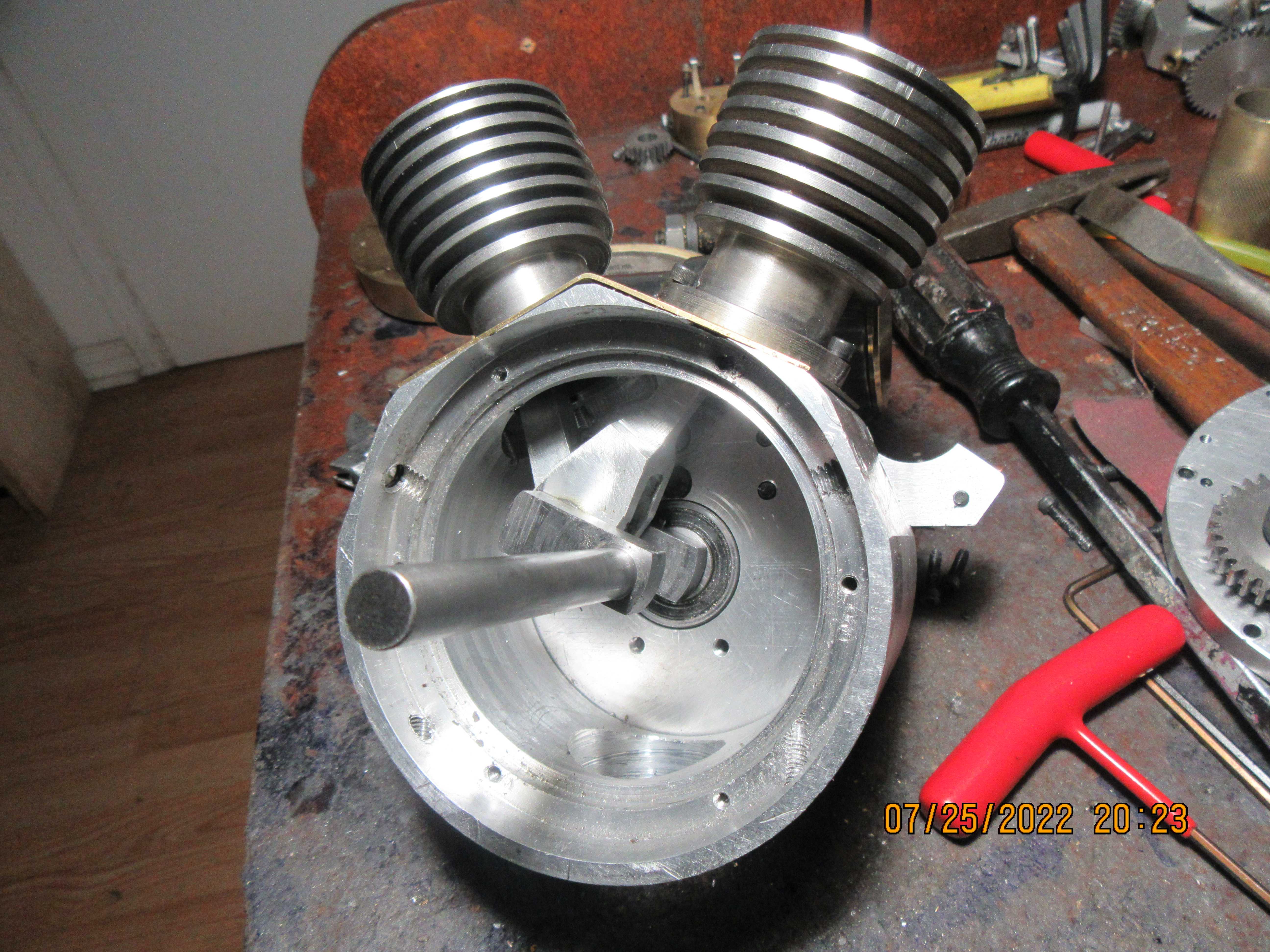
Things are back together, and it all fits ---and that's a good thing. I can't rotate the crankshaft thru a full 360 degrees because I'm getting some interferance between the connecting rods and the bottom/inside of the cylinders. I did end up drilling a 1.25" diameter hole thru the bottom of the crankcase to let me tighten the con-rod cap bolts. Tomorrow I will sort out the clearance issues.
AH7heo.jpg

OP6LJp.jpg
 
The engine has been "run in" until the crankshaft will turn freely with the rod cap bolts tightened down. Hopefully, I can get my 0.094" slitting saw back from sharpening this week, and cut the cooling fins into the cylinder heads. I have to make a bolt-on plate to cover the hole in the bottom of the crankcase, and have to put a hole in the side of the crankcase for an oil filler pipe.----This engine will have oil in the base for splash lubrication of the connecting rods and wrist pins. I haven't made the valves or the valve cages yet. There will be a pair of gear guards made to cover the camshaft gears, but I won't make them until after the engine has been ran. Probably will be ready to start the engine by mid August.
 
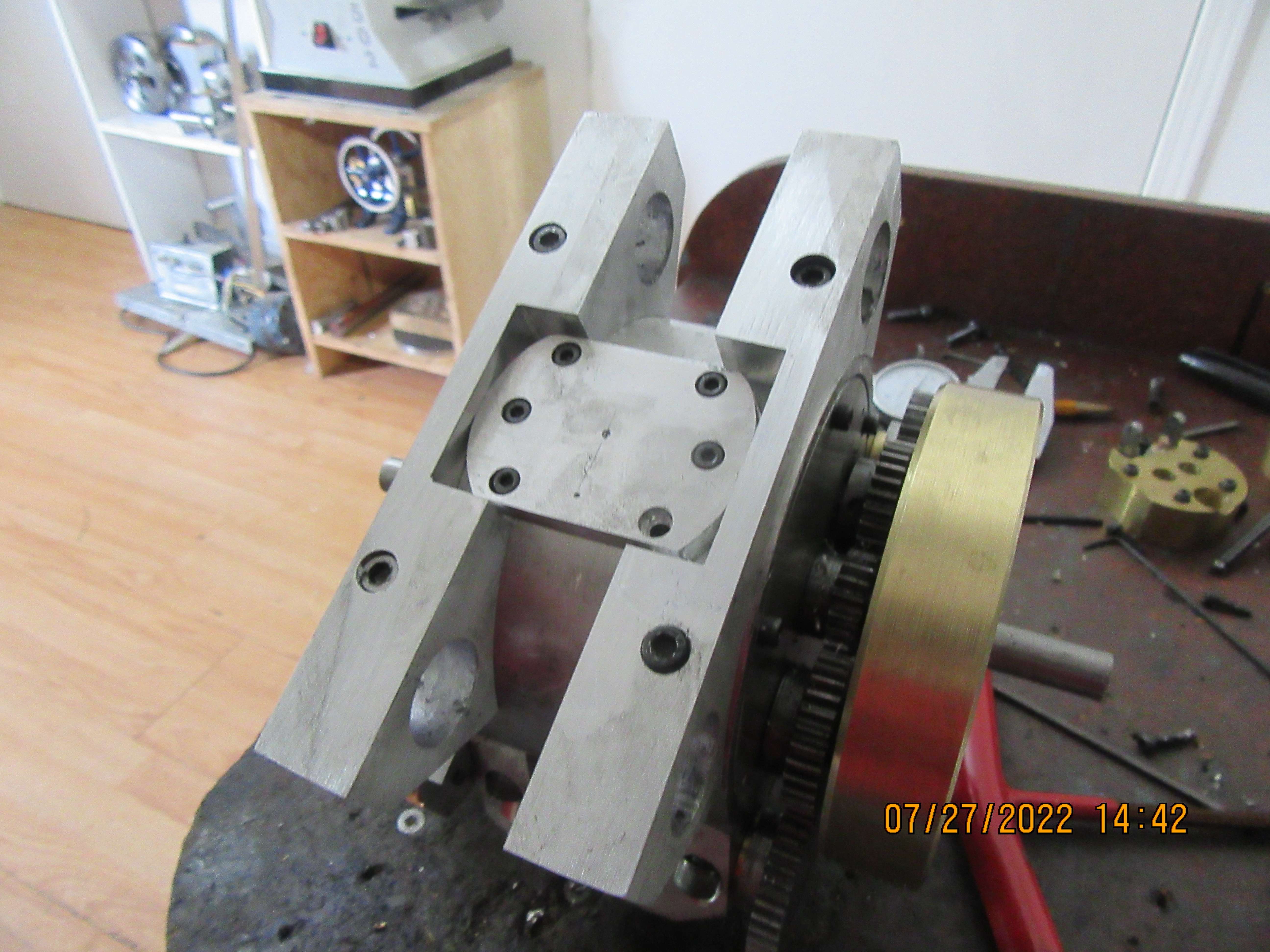
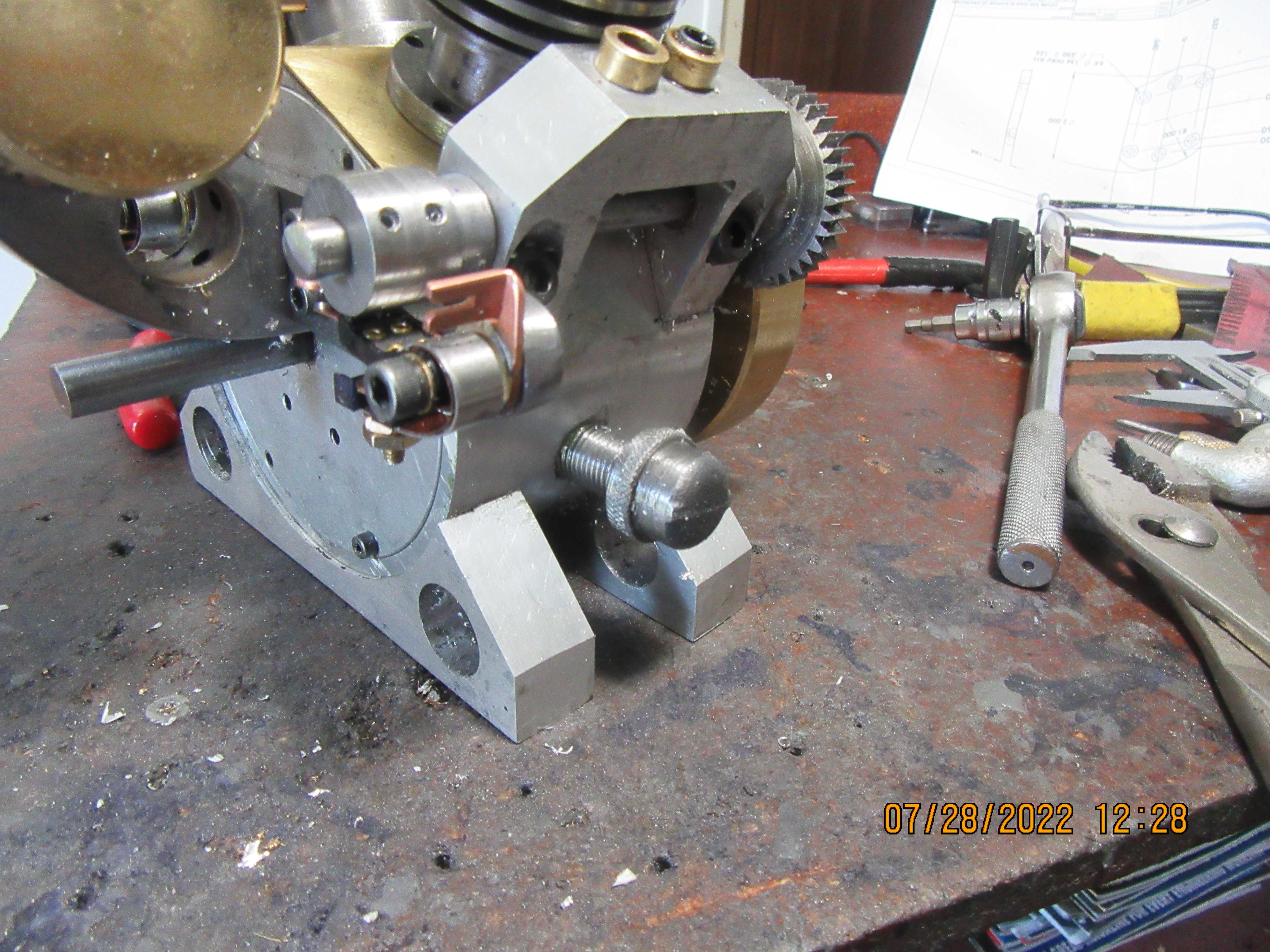
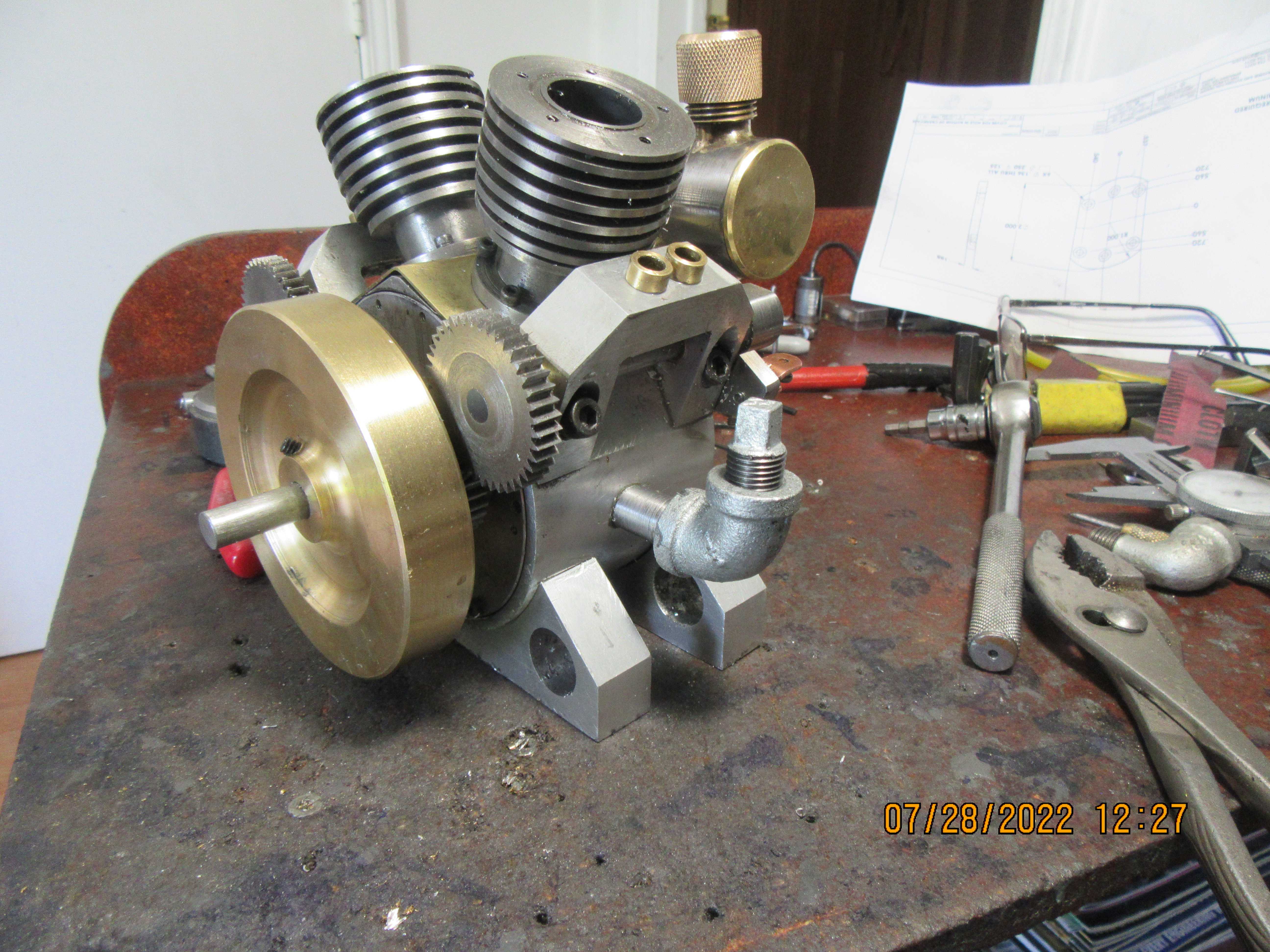
So, what do you do when you've cut a great big hole in the engine crankcase to give wrench access to the rod cap bolts? Well of course, you make a cap plate that screws onto the crankcase hole to give it leak proof cover. This of course means milling some material away on both of the crankcase support feet so that the cover plate can be taken off in future without having to remove the crankcase feet to do so. Now I'm off to the hardware store to see what they have in small diameter black iron pipe that might work for an oil filler spout.
hr64hG.jpg
 
Now we have a place to put the new oil in, and a slightly lower place that the oil starts to run out of when the crankcase has the right amount of oil in it. Somehow, this was far more difficult than I had assumed it would be, but it's done---even if it did take me an entire morning to do it. Sid suggested that the oil level in the engine should be lower than I initially planned, so I dropped the oil level another 1/4" from where I had originally intended it to be.
30XR1f.jpg

IWETch.jpg
 
Hi Brian. Splash Systems consume loads of power, so an oil level just below the crank and con-ròd is OK with a small - say 1/8" diameter or smaller by 1/4 to 1/2 in long rod fixed in the bottom of the con-rod to just hit the oil and cause the splash is adequate.
K2
 
Brian
Oil is like exercise its over rated. 🤣🤣🤣
Just having some fun the build looks great can’t wait to hear it run
 
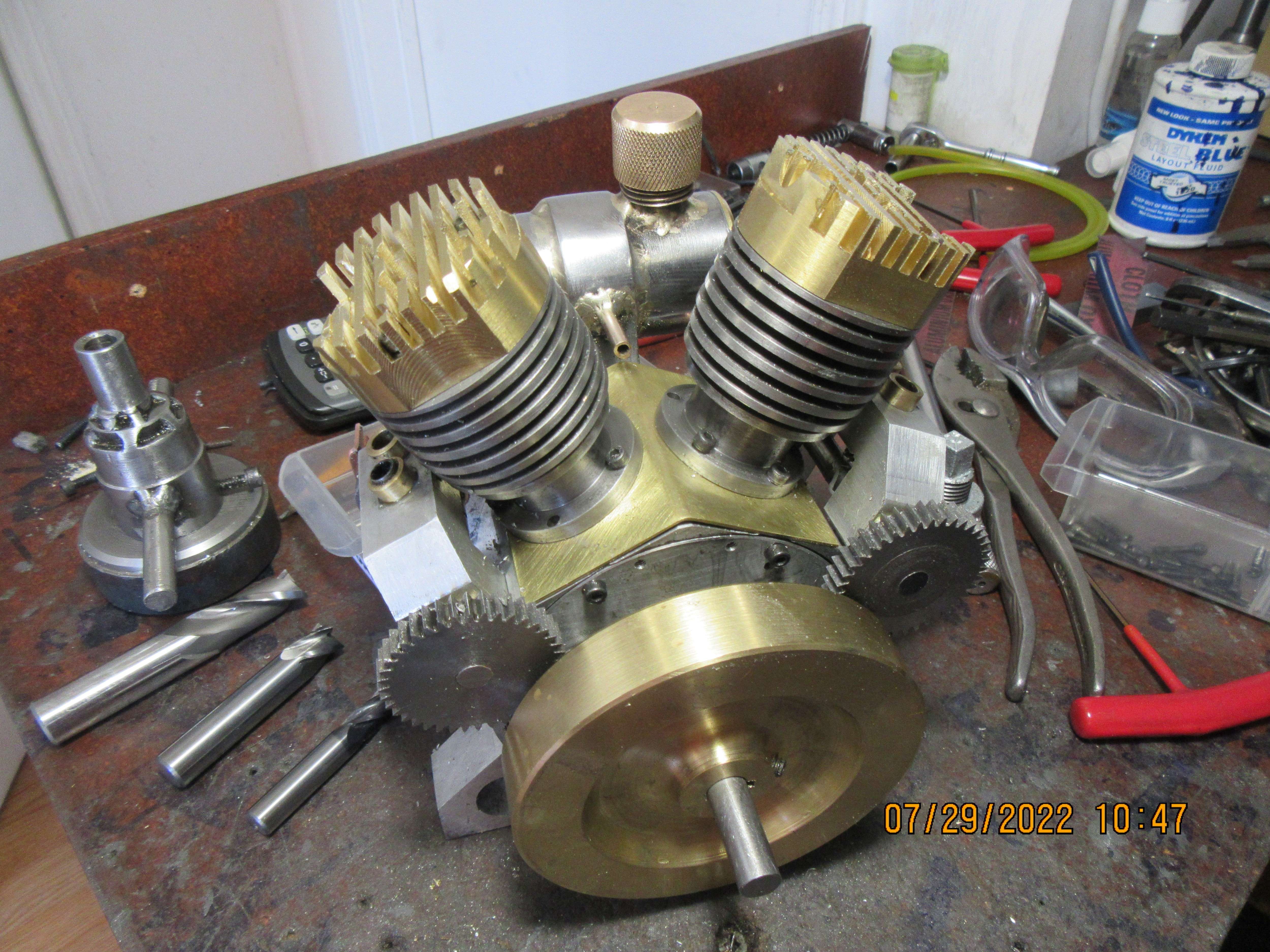
Now I have to ask Is that a beautiful thing, or what? I had a bad attack of lazy yesterday afternoon so I drove down to Alcona and picked up my sharpened slitting saw from my tool sharpener man. He does great work. This morning I cut the fins into my cylinder heads, and I'm really happy with the results.
nlHLVI.jpg
 

Latest posts

Back
Top