V-TWIN---MAYBE V-4

Home Model Engine Machinist Forum

Help Support Home Model Engine Machinist Forum:

This site may earn a commission from merchant affiliate links, including eBay, Amazon, and others.
Exhaust Details
ZAtCOD.jpg
 
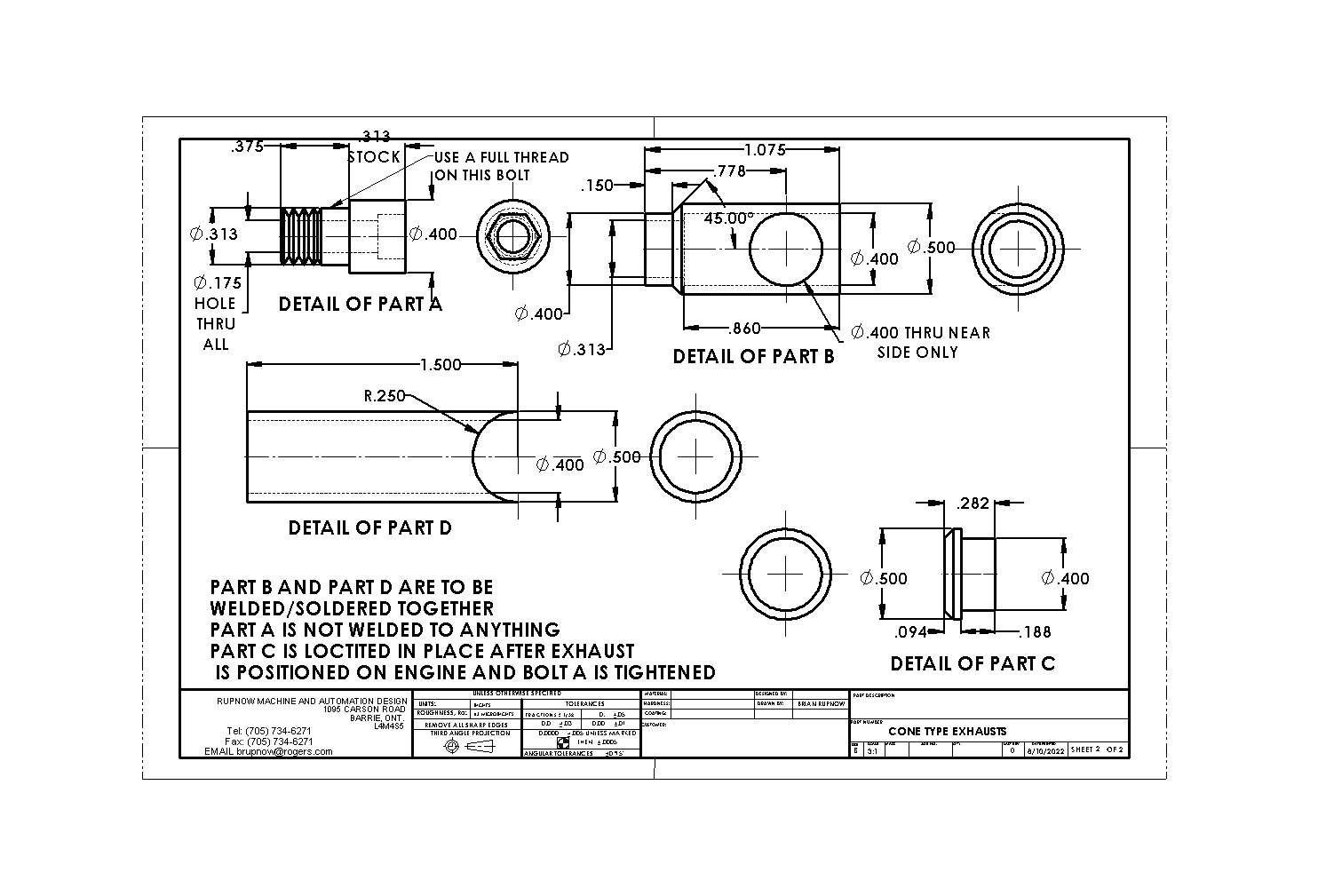
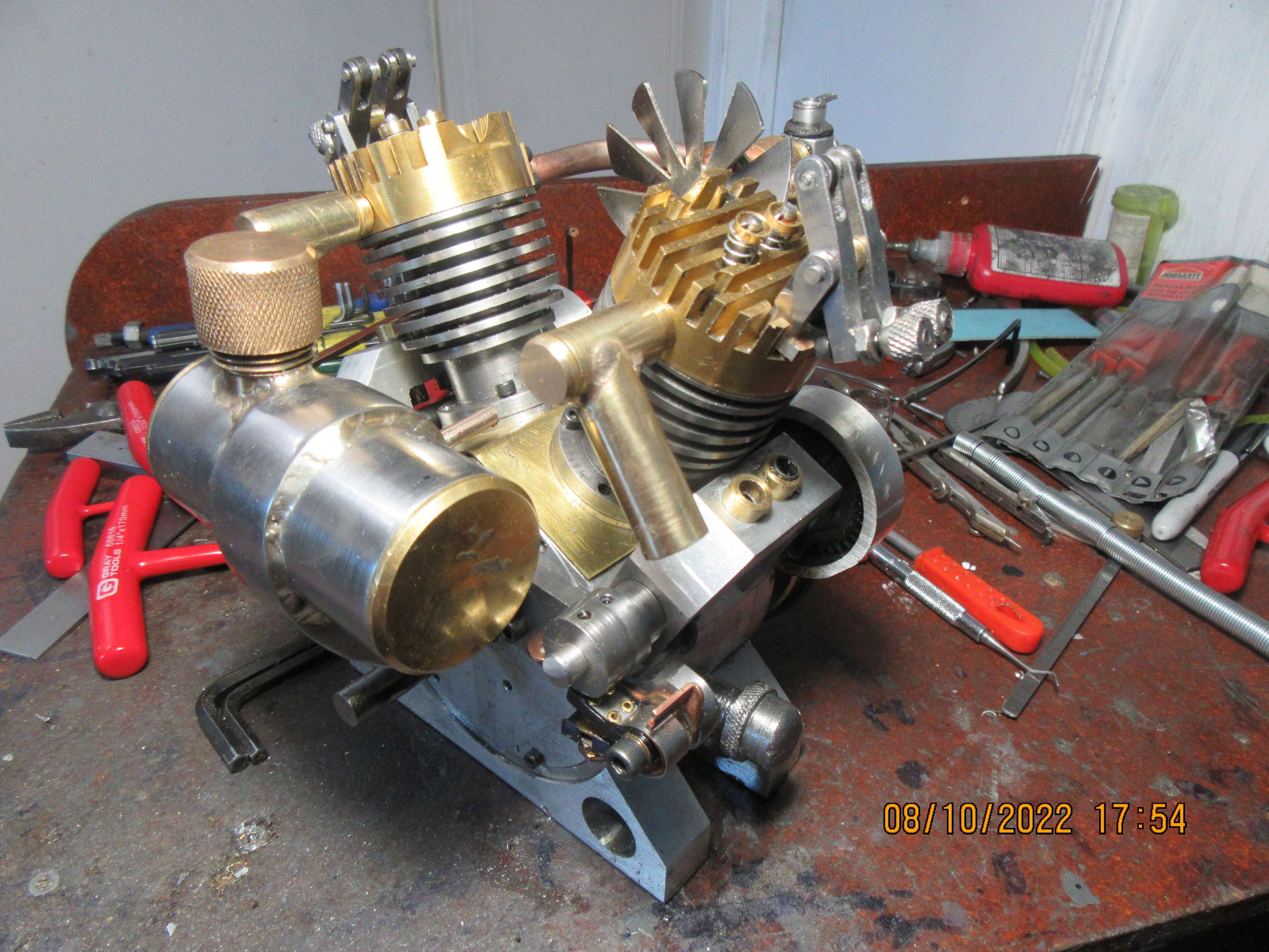
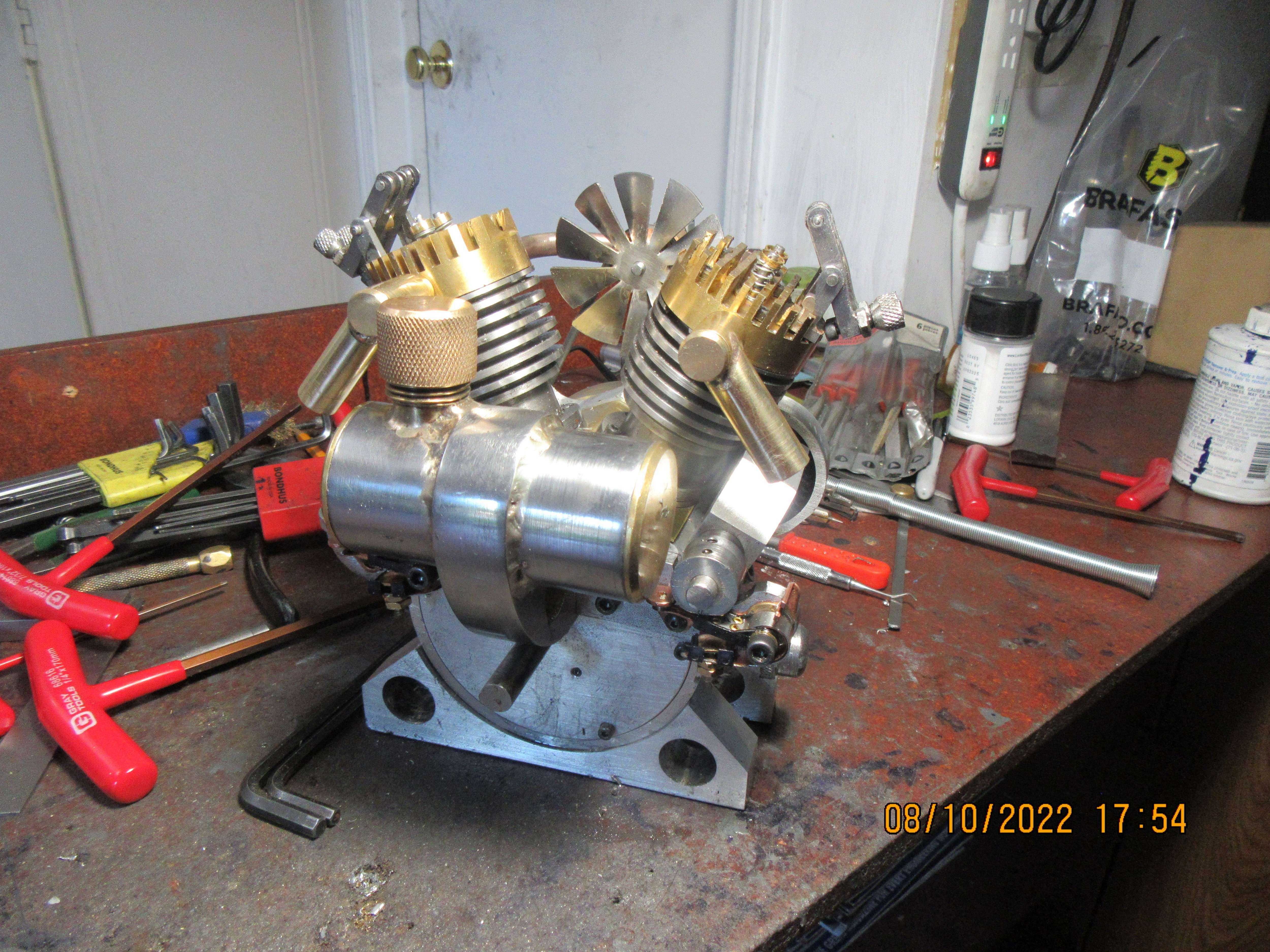
I'm very happy with the way this turned out. I especially like that I can adjust the angle of the exhaust pipes to be any place I want it. If I want to remove the exhausts, I can heat the "cap" with my torch to allow me to remove it and access the bolt which holds the exhaust to the cylinder head.
jM4hTz.jpg

xmhRSu.jpg
 
I think that just about covers everything except the cams which operate the valves and the pushrods. I still lack one bearing for the fan, but it is supposed to be here this week. I may discover the odd thing here or there as I go to finish everything up, but by and large, the heavy duty machining and fabrication is finished. I started this build on the 15th of June, and by the 15th of August the cams should be finished. I have worked on this engine every day since I started building it.
 
Brian
It looks great that was a good work up of the exhaust. Sounds like we may see a running engine in a few weeks
Tom
 
Brian, I love the look of the exhausts. I am curious about two things: 1) will this design cause undue back pressure on the exhaust (constriction, sharp 90° turn), and 2) how would one tell if that were the case??
 
Awake---the sharp 90 degree corner will have some effect, although it may not be measurable. The only way to tell if your exhaust system is causing too much backpresure is that eventually your exhaust valves will burn out.
 
Ah, interesting. I hadn't thought about the effect on the exhaust valves. Thanks for the response - I know just enough to know that I don't know very much at all about the ins and outs of engines, model or otherwise.

Of course, no more than I tend to run a model engine, it might take 100 years to make a difference ... :)
 
HELP!!! I know that there are two main methods of cutting cams for these small i.c. engines. One method uses a vertical milling machine and a printed out set of offsets that will give you the cam profile that you want if followed precisely. I have used that method in the past, but windows 11 seems to not run the charts I originally used. The other method also uses the vertical milling machine and after initial set up there are no charts used in machining the cam. I THINK someone has set up these offset charts for the first method on an excel spreadsheet. I would like to use the first method with the excel spreadsheets, because it lets me cut all four cams at once. Can someone please point me to a post where I can download and use these excel spreadsheets, and perhaps a post where it all gets explained. It has been a long time since I used that method of cutting cams.---Brian
 
HELP!!! I know that there are two main methods of cutting cams for these small i.c. engines. One method uses a vertical milling machine and a printed out set of offsets that will give you the cam profile that you want if followed precisely. I have used that method in the past, but windows 11 seems to not run the charts I originally used. The other method also uses the vertical milling machine and after initial set up there are no charts used in machining the cam. I THINK someone has set up these offset charts for the first method on an excel spreadsheet. I would like to use the first method with the excel spreadsheets, because it lets me cut all four cams at once. Can someone please point me to a post where I can download and use these excel spreadsheets, and perhaps a post where it all gets explained. It has been a long time since I used that method of cutting cams.---Brian
Brian, Is this the post you have in mind Link CamCalc - Manual Numerical Control | Model Engineer Click on the link within the post

Mike.
 
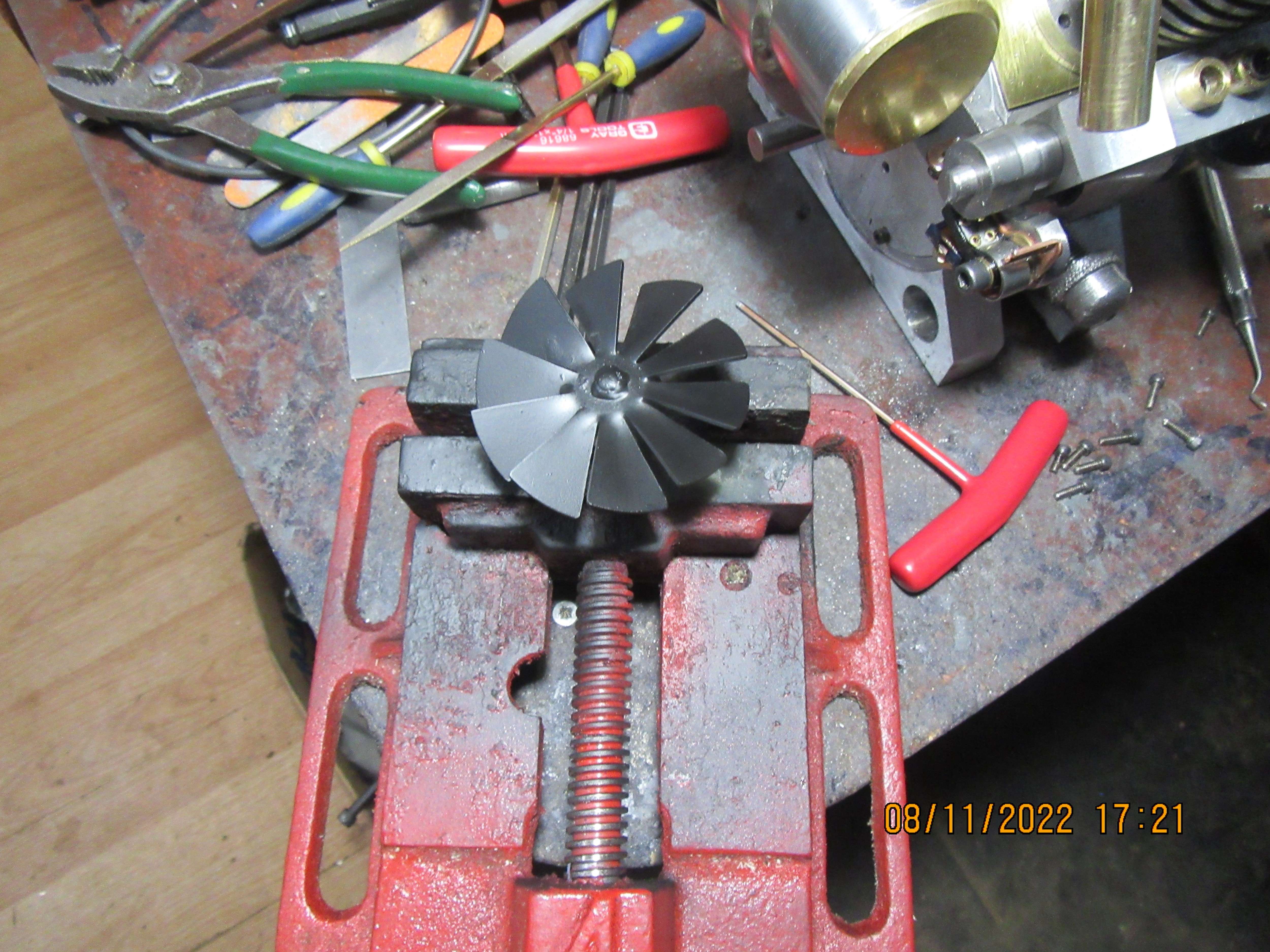
I did surprisingly little today, and Damn, it felt good!!! I did complete the assembly of the fan, fan shaft, two roller bearings and a bearing spacer. After it was finished I painted the fan and fan pulley with a couple of coats of flat black enamel. It is still quite "fresh" in this picture---it will get flatter as a bit of time passes. I will assemble it with the rest of the intake manifold tomorrow. I did get a response to my request for a post about the cam-calc method of machining cams, and will take a deeper look into it tomorrow.---Brian
ZvaVbo.jpg
 
When making a cam how important is it to have a radius on the flank? There is only a few thousands of lift and the action actually takes place at the nose. As long as the valve opens and closes at the proper time how does a gentler action make it any better. We are talking about engines run at low speeds and for limited time. If the cam or cam follower wore out after 5000 hours none of us would ever see it. I have made cams successfully with a straight flank as shown on several plans that I have followed.
 
General theory is that if the cam has a flat flank, then the flat flank rotates around and "slaps" the bottom of the lifter each time the cam rotates. This supposedly causes early failure of the valve train because of the vibrations caused by these repeated "slaps". Is it a real concern? I don't really know. Apparently cams with flat flanks should only be used with roller cams that have a wheel attached to the portion that comes in contact with the cam.
 
The flank radius does a few things. One it helps to accelerate the opening of the valve in a controlled way. It's kind of like pushing the valve open unlike a flat flank is more like hitting a baseball with a bat. That's a gross exaggeration but kind of gives you the general idea.

The flank radius also has an effect on how big or small the bottom of the lifter has to be. If the bottom of the lifter is too small the bottom edge will dig into the flank as the lobe comes up to the top and then skid down the other side of the flank. I have seen some people get around it by putting a large radius to putting a ball end on the bottom of the lifter. Eliminates one problem but now the only contact between the lobe and lifter is a small contact patch dead center of both parts. At the scale we build them with the couple pound springs and the infrequent running of the engines I doubt either would wear our in our lifetime. A flanked radius with a large enough lifter and there will be a contact patch as wide as the lobe giving a far better design.
 
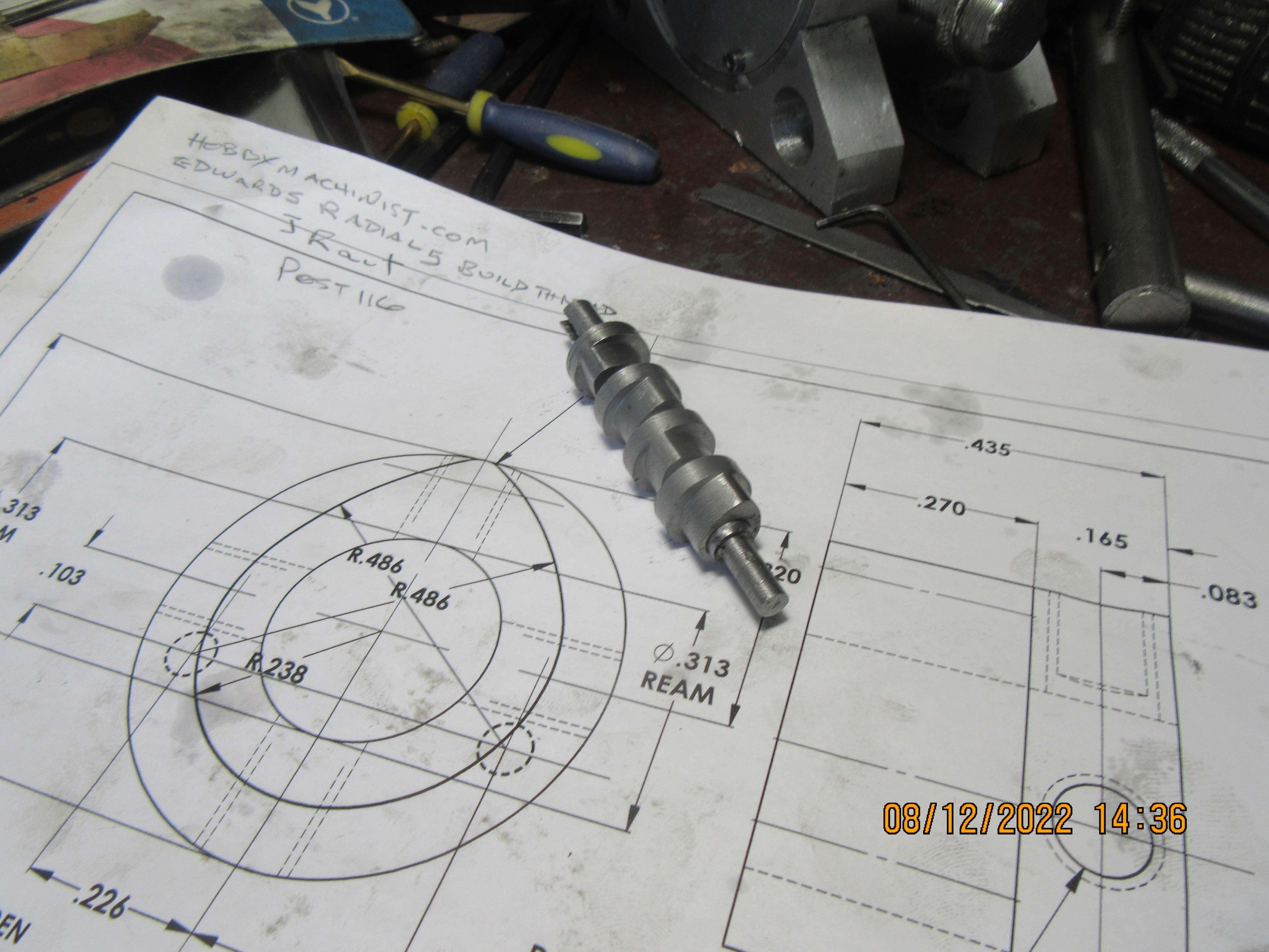
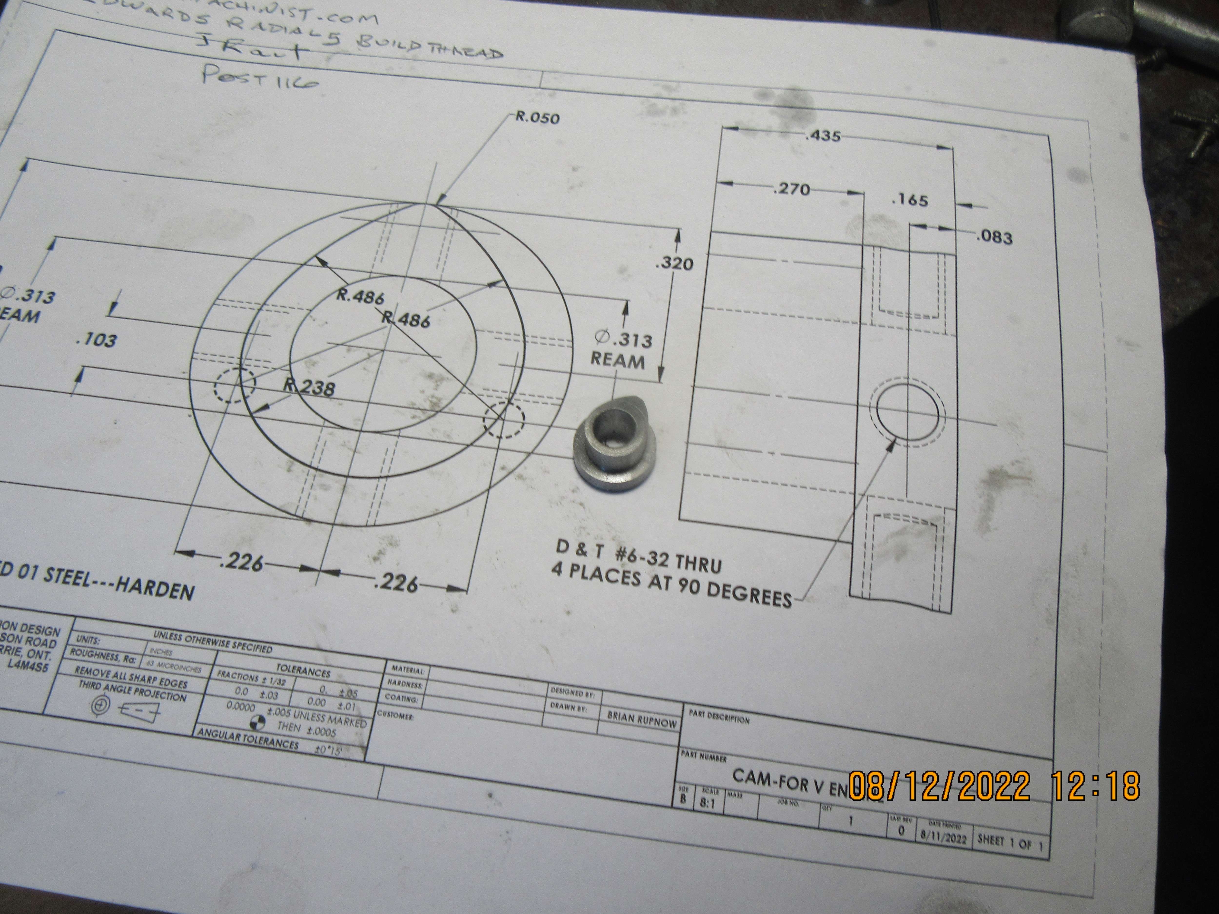
Today, I'm making cams. Unfortunately, I was not able to use the cam-calc tables that people so kindly sent to me. It could be that my software won't run it, but it is also possible that since I have very little knowledge of Excell spreadsheets I didn't know how to operate it properly. That's okay, my method yields a perfect cam with radiused flanks. There are no mathematical tables to use, but my right arm may fall off from taking the 90 plunge cuts required to do this right. I am going to start another thread on machining the cams, but for now, this is the cam that my method yields.
oG7kq7.jpg
 
Thanks Steve. That is pretty much what I thought but as you also said when we are talking about low RPM, low power and low usage engines it seems like a lot of work for not a great deal of advantage. Some folks here are building high speed engines so that flank radius may be more important but most of us are trying to run our engines as slow as possible and a run of 15 minutes is a long run. If you are designing automobile engines to run at high speeds for 100,000 miles you are in a different situation.
 
So there we have it. Four little cams with curved flanks, all in a row. And really, I've been about 5 hours getting to this point. They are all made from 01 steel, and will all be flame hardened and quenched. Before I harden them, I have to drill and tap them for set screws. That 5 hours includes turning a piece of 3/4" 01 steel down to 0.640" diameter, sawing off four lengths about 1 1/4" long with my bandsaw, squaring the ends of each piece in the lathe, and drilling/reaming each of the four pieces to 5/16" diameter. They're not exactly the same, but they were all done on manual machines.
AhKia5.jpg
 
Yes Gordon, very true on all accounts. One thing I didn't mention was longevity also depends on your choice of material. If you run a flank radius not a big deal but options b and c with the modified lifter bottoms it's important. Brian chose O1 tool steel for a cam shaft. Very good choice even if he didn't harden it. I also make my lifters out of 12L14 leaded steel. The lifters are softer than the cam so they wear faster. Easier to make than a new cam. With that combination, as long as they get a little oil splashed on them, they will out live both of us.
 
Steve--I do flame harden and oil quench the cams and the lifters. That's why I make them from 01, so I can harden them.---I just did that to the cams I made earlier today.---Brian
 
Back
Top