Upshur's opposed twin engine

Home Model Engine Machinist Forum

Help Support Home Model Engine Machinist Forum:

This site may earn a commission from merchant affiliate links, including eBay, Amazon, and others.
An other way : Fix the 2 lobes on the shaft at an angle of 102 degrees, then adjust the position of the gear.
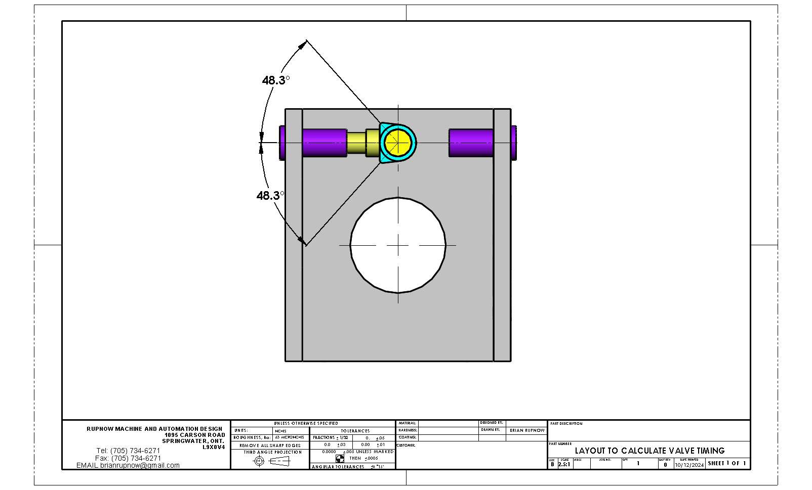
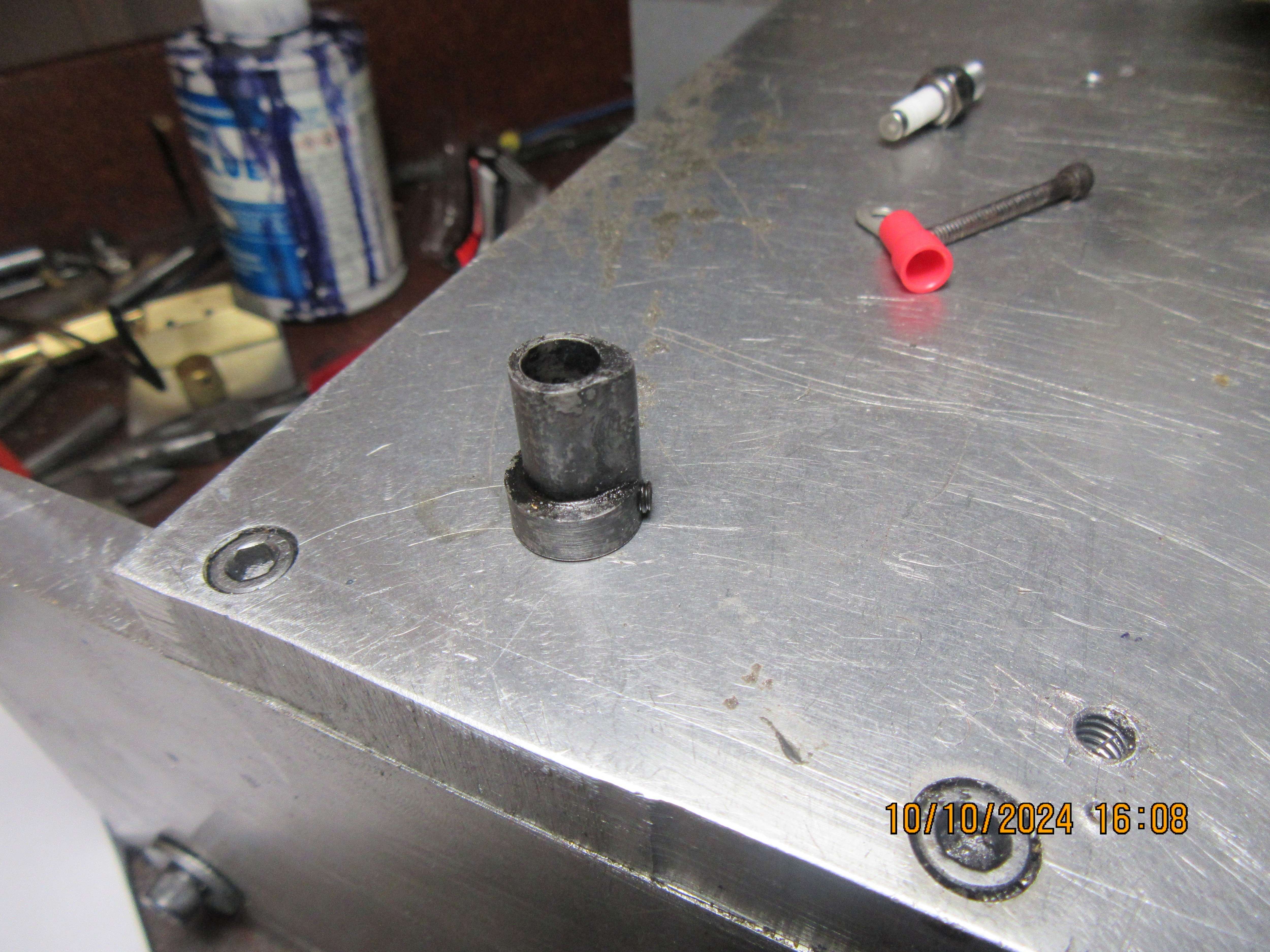
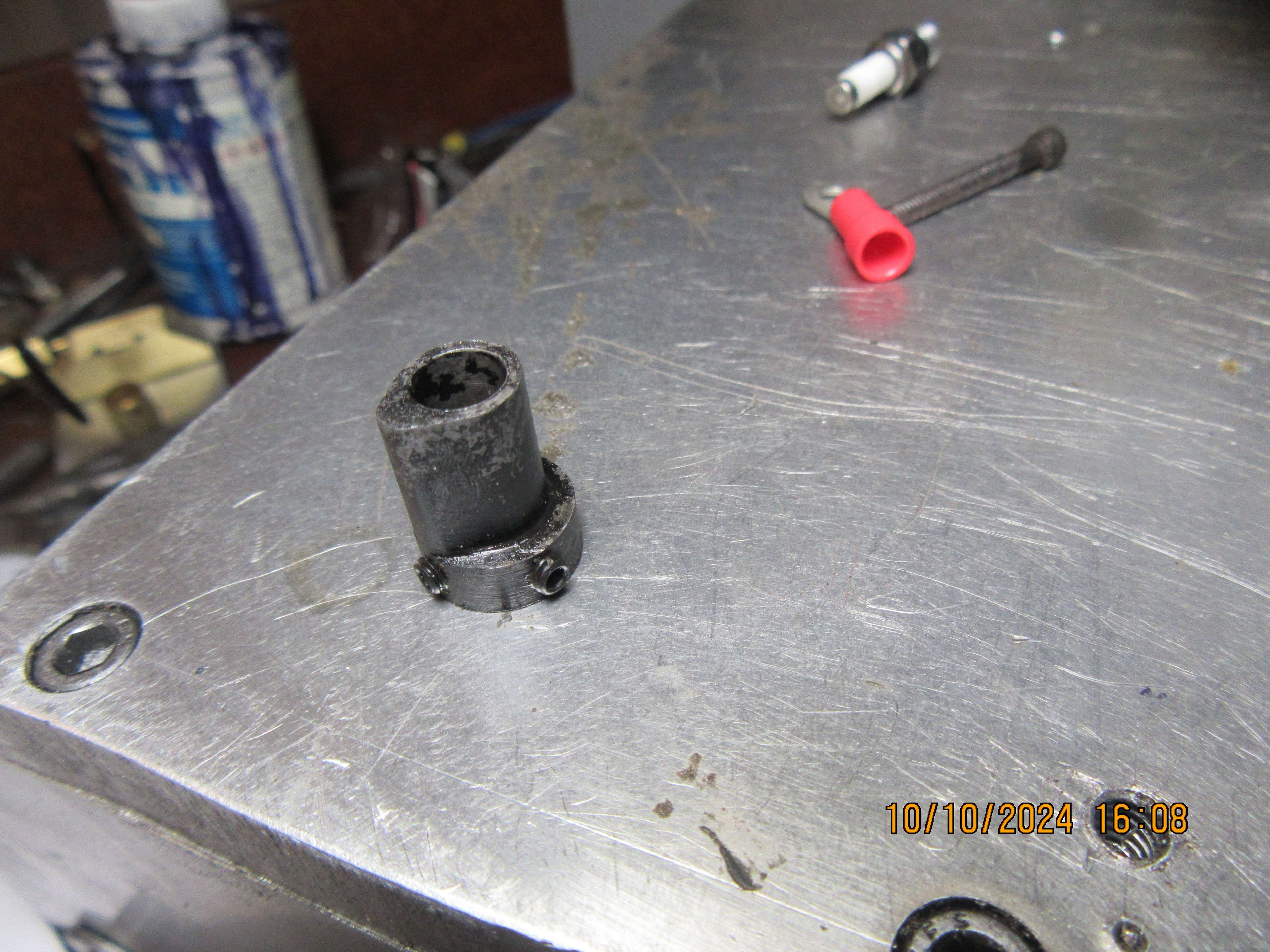
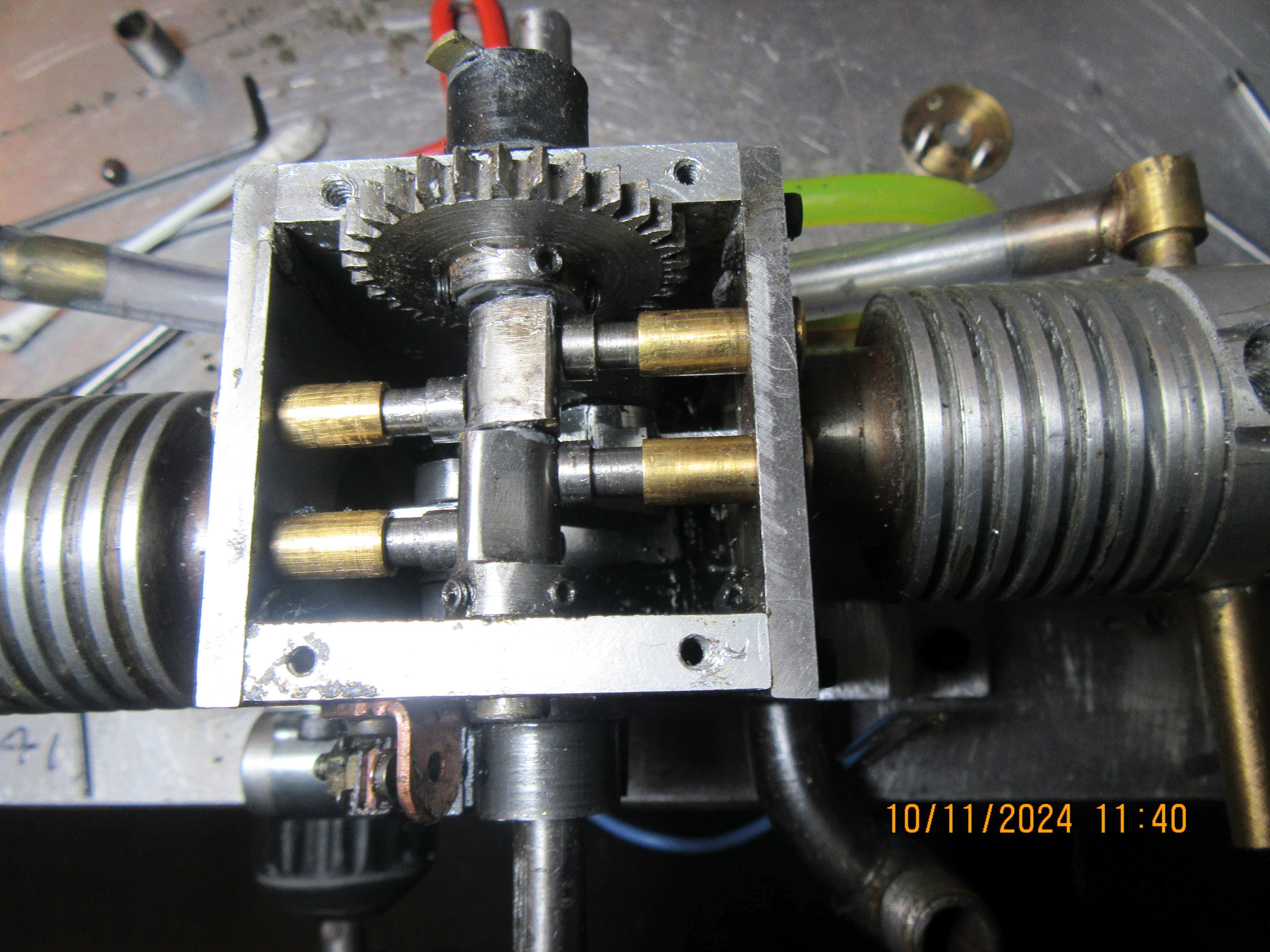
You need to have the correct cam leading.

Brian why not Loctite the two cams in place, if you get it wrong pull the shaft out, heat to break the Loctite and then reposition the other way round. Saves making a new cam with screw boss.

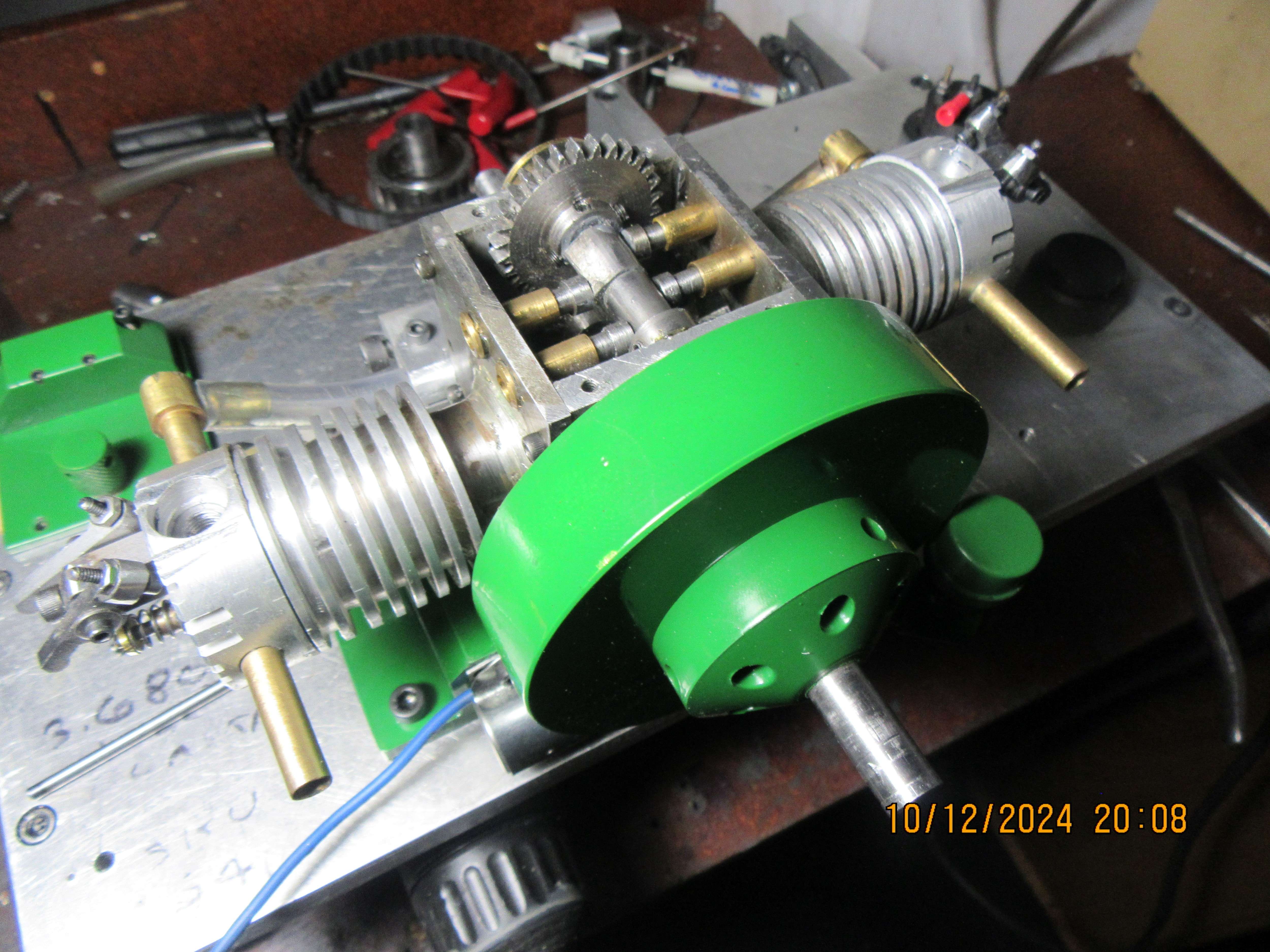
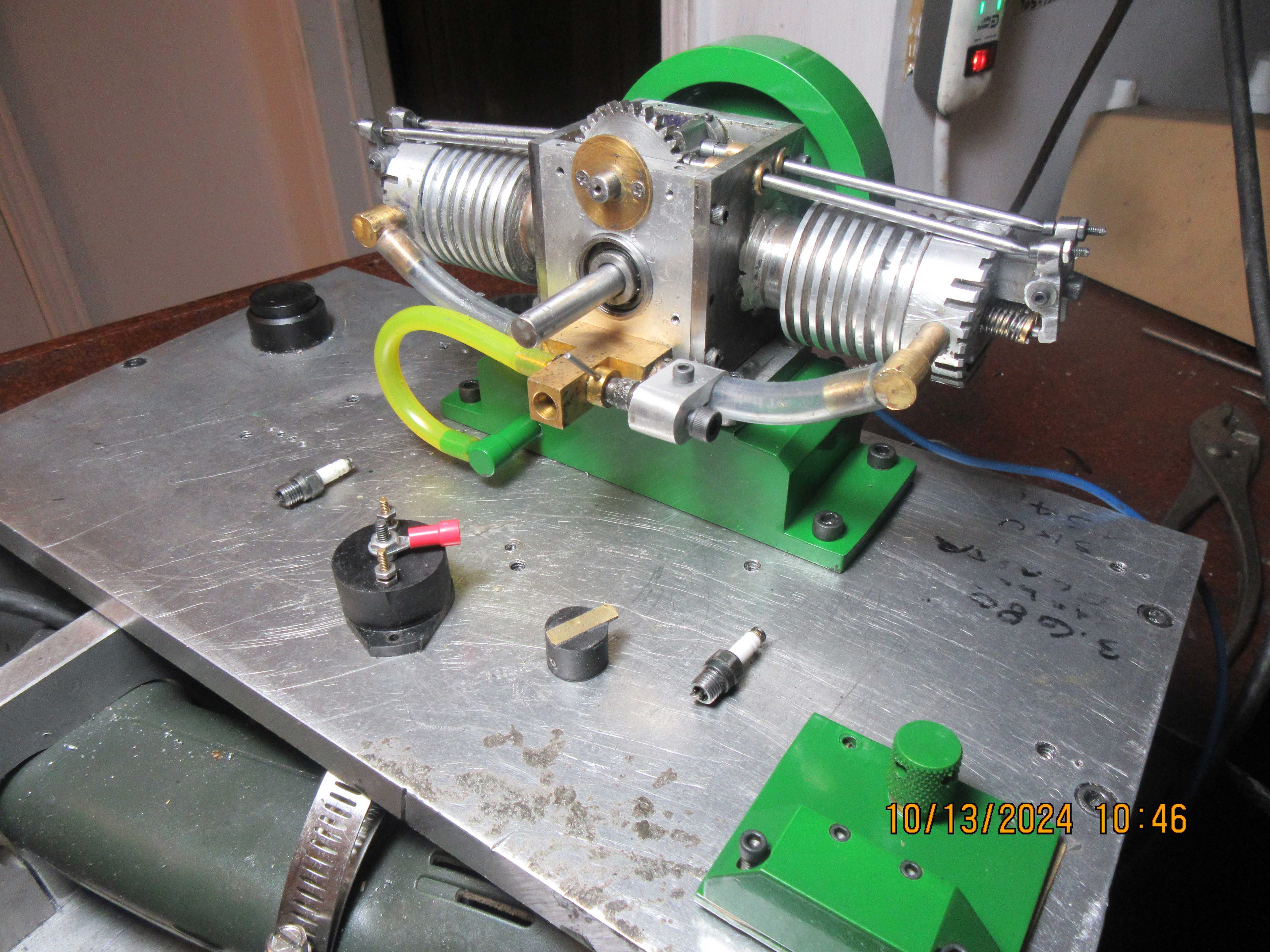
As I and others have said forget about the 2nd cylinder, just turn the engine over by hand and get the first set up as you have done with previous singles which will soon show which way the two camsneed to be set. The second cylinder will take care of itself apart from a bit of lash adjustment.
 
Not a lot got done at the Rupnow house today. We did make one cam with a hub and set screws. I thought a lot about loctiting the cams in place and trying to see if I got it right, but its a major job to do that and then find out I got it wrong. My powder paint is at my front door and I haven't had a chance to go and get it yet. That's all my machining today.--I haven't even given the new cam a bath yet. I just photographed it straight from heat threat.
ToKzZ7.jpg

Rw5h6V.jpg
 
So here we are, one cam J.B. Welded to the shaft, other cam with set screws wiped with greasy q-tip inside so it won't stick to the J.B. weld, and the gear wiped inside with grease so it doesn't stick to the J. B. Weld. This seems like such a simple thing, but it took me two hours to do this. Now it's time for some lunch!!!
RB09tI.jpg
 
Today I'm figuring out how far powder paint goes. I paid $26 per pound. With my trusty teaspoon I put 10 tea-spoonful's into my powder paint gun bottle. I painted everything multiple coats---the reason being that I can only spray what faces the opening in the spray booth. I turned the aluminum sheet everything was setting on about 6 times to ensure that I got full coverage on everything. (the ground was hooked to the aluminum sheet) Then with my trusty teaspoon, I put 9 teaspoons of powder from the gun bottle back into the bag of powder paint. That's right---one teaspoonfull of powder to paint everything at least six times. That included the flywheel, the coned front of the flywheel, the top plate, the cam gear cover, the air breather that sets on top of the top plate, and the large base/gastank and the threaded cap that screws onto the gas tank spout. Everything is now setting in the curing oven, where, if I have lived right the powder is melting and flowing out into a gloss finish.
pIPj2n.jpg

XTRFaL.jpg
 
This is the green paint glossed out after the oven had cooled down. My main concern was "Would a powder paint from Emerald Coatings flow and gloss out using an oven from Eastwood?" The question has been answered in a most satisfactory manner. Tomorrow I will start putting everything back together and see if this thing will run.---Brian
YcSkQK.jpg
 
I have the engine reassembled, and it looks really good. Looks like a John Deere tractor!!! I am puzzled by the notes regarding the valve timing on this engine. The note says "Viewed from the flywheel end of the engine, set the left (1 piston) on top dead center. Loosen the distributor rotor. Slide it back to allow the camshaft to be slid forward just enough to disengage the gears. Re-engage the gears where the left cylinder cam followers rise approximately an equal amount for the same crank angle on either side of top dead center. If the rise is not equal, slide, engage the tooth which favors early intake follower rise with ccw flywheel rotation." ---I don't have the faintest damned idea what this really means. Normally on these small engines I set the intake valve to begin opening about 15 degrees before the piston reaches top dead center. The shape of the cam determines when the valve closes--(I followed the drawings to make my cams). Can somebody set me straight on whatever I'm supposed to do here please.----Brian
 
The way I would do it is to set the pistons at TDC and get one cylinder with the lifters rocking, that is exhaust closing and intake opening. Once this is confirmed rotate the engine crankshaft one revolution and look at the other cylinder. This cylinder should now have the valves rocking, ie Exhaust closing, Intake opening. Make sure you rotate the engine crankshaft in the direction you want the engine to run. Hope this helps.
 
This is what I thought it meant, but this is very fishy. Using models created from the Upshur drawings, I placed one side of the cam right up to touching the cam follower, but not yet lifting it. Then I placed an overlay of the same cam on the other side of the cam follower, but with the cam follower just touching it, as it would be when the cam follower was fully "not lifted". 48.3 degrees is a long way from the 15 degrees I have used on all my other engines.
LDKTID.jpg
 
Yes, the drawing is to scale. Perspective is weird sometimes.
Ok. Proportionally the head on the lifter is huge compared to the lift lobe on the cam. That will have a big effect on valve timing, greatly increasing the duration. I am sure you made them to the drawing dimensions. The ratio of the lifter head do the cam lobe just seems much much different than the norm by eye.
 
As shown in post 351, the cam duration is 96.3 degrees. On other engines I have built, the cam begins to influence the intake valve 15 degrees before the piston reaches top dead center and stops influencing the intake valve when the piston is 45 degrees past bottom dead center.---This is of course, assuming 0 valve lash. So, the cam duration on those engines is 15 + 180 +45 =240 degrees. It's quite possible that I am not understanding the Upshur instruction sheet. if I take that 96.3 degrees and add 180 degrees to it, then I have 276.3 degrees, which gets me a lot closer to the 240 degrees that I generally use.
 

Latest posts

Back
Top