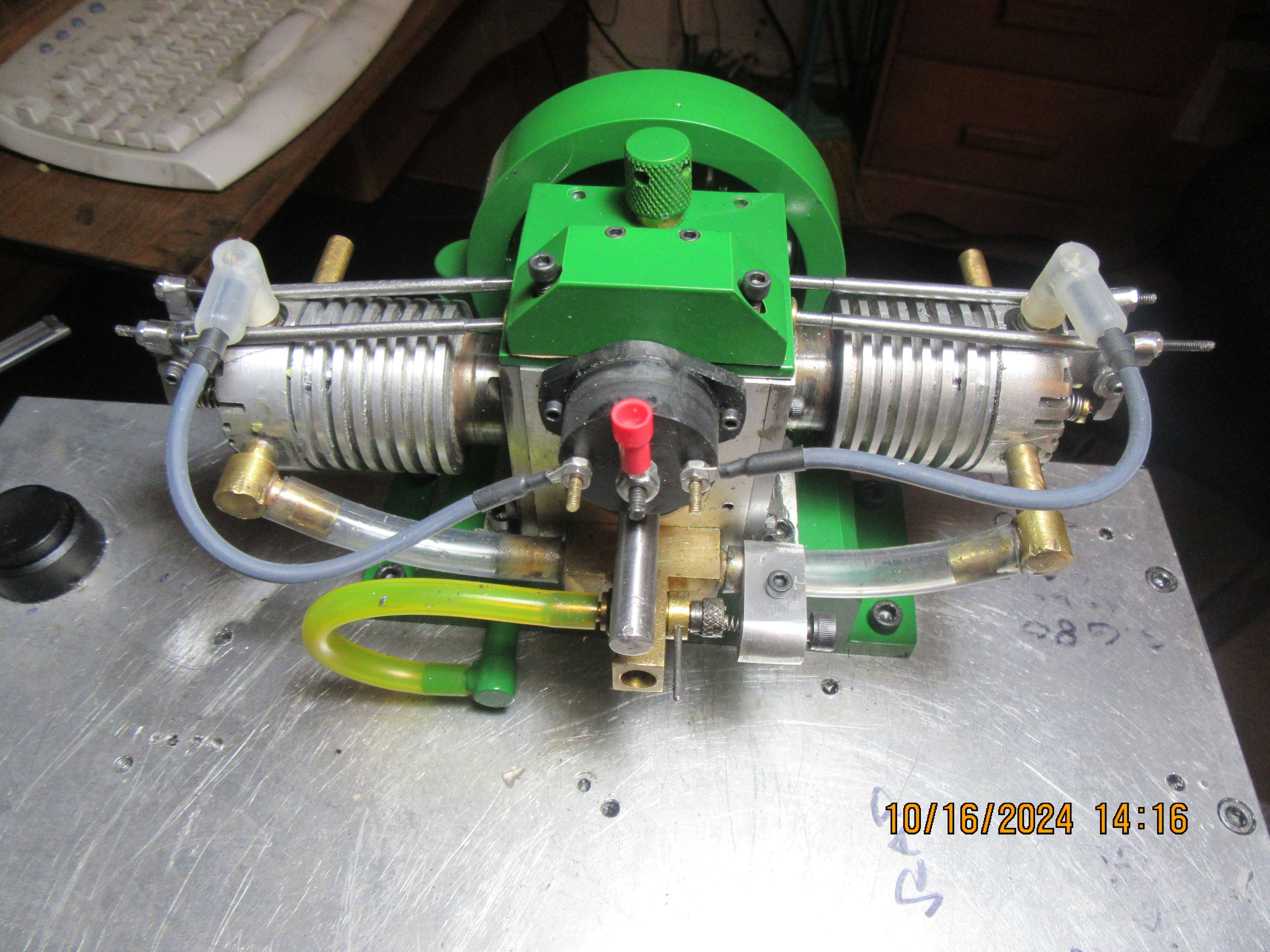
Upshur's opposed twin engine

Home Model Engine Machinist Forum

Help Support Home Model Engine Machinist Forum:

This site may earn a commission from merchant affiliate links, including eBay, Amazon, and others.
Here you go Brian, that same assembly being rotated

Read the bottom right first to see what is going on with the right side cylinder then watch again to see how the rear one follows 360deg of CRANK rotation later. This is for the Bobcat based engine as I have the parts modeled. You can do the same with yours and then do it again with the Upshur arrangement and if you have it right will get the same results.

Watch it full siz eon Youtube.


two cams compared, see how the two inlets and th etwo outlets face the same way.

no different.JPG
 
Last edited:
If your CAD allows you to set gear ratios and directions then just assemble these few parts and turn the crankshaft round and watch what the cams do.
Brian uses Solidworks which should have mates and motion capability as well as gear ratios. I have never seen him use that feature in any of his builds. (it is possible I missed a post or course)
 
I use Solidworks all the time when figuring out valve timing. I don't post about using it because there is nothing to see unless you have the program.
 
I use Solidworks all the time when figuring out valve timing. I don't post about using it because there is nothing to see unless you have the program.
You can use screen captures and/or motion study video captures in Solidworks.
I use motion study a lot to verify that the parts fit.
If the parts don't fit, the engine and/or mating parts won't rotate in motion study.
One of the more useful engine design features I have ever seen.
.
 
That is good that SW can do it so you should be able to do as I have done and see how the timing works, saves having to keep pulling the engine apart. Look forward to seeing the running engine.

Not everyone has Alibre but the video and screen shots I post allows anyone to see how things should work so that is why I post it, often a picture/video is better than words.
 
I use Solidworks all the time when figuring out valve timing. I don't post about using it because there is nothing to see unless you have the program.
You should be able to capture the SW movement in a mpeg or an avi file and post it???

Sid
 
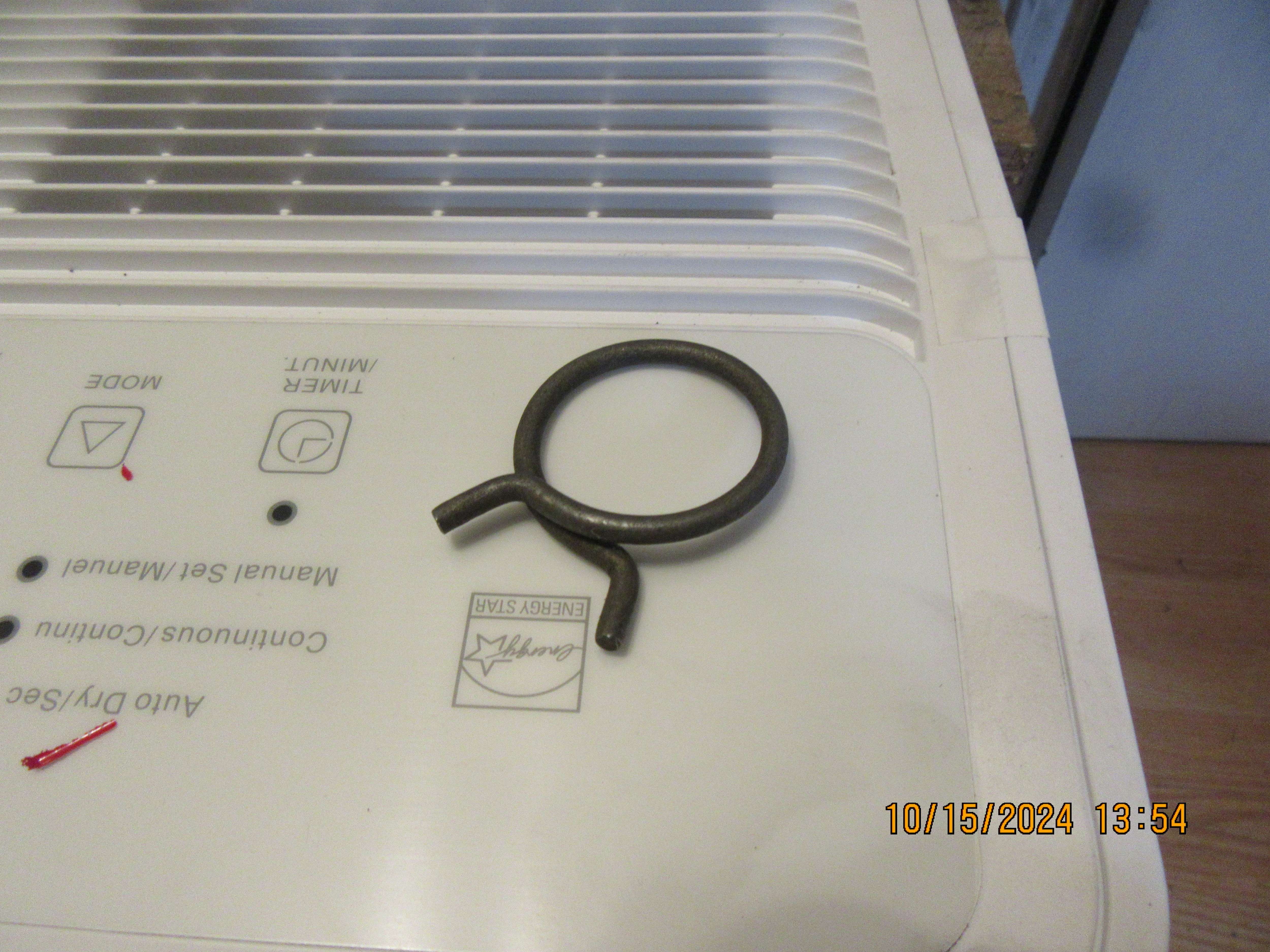
Question of the day---What do you call this particular sort of spring clamp and where can I buy it to fit 1/4" and 3/8" gas lines. Preferably in Canada.
ab7rGs.jpg
 
I'd also suggest you look at that cam you made a couple of days ago, looks nothing like the first pair you made, not sure what you have done, either wrong duration or a much larger nose radius which is likely to result in a lot less lift if you started with the same size material.

Originals
old cam.JPG


And this is the one you just made with the grub screws. You are going to have problems timing it with different cams
new cam.JPG
 
Last edited:
Question of the day---What do you call this particular sort of spring clamp and where can I buy it to fit 1/4" and 3/8" gas lines. Preferably in Canada.
ab7rGs.jpg
Just use a wire tie.
Are you looking for excuses to delay starting?? :cool::cool:
 
If you can't find exactly the host clamp size you're looking for you might try this I've used it many times and with a little practice actually makes a pretty good looking and very solid clamp

https://clamptitetools.com/
There's a how to select the right tool video on their site that shows how it works and you could likely build the tool in a hour but they aren't too expensive.
 
This morning my sparkplug wire assemblies came in from Roy Sholl. Every time I build an engine I swear that I'm going to make up a die set and cast my own sparkplug boots---and every time I end up ordering a set from Roy.
ATElOO.jpg
 
so on those boots. ive seen the posts on making them but wanted to know. is it the tension of the silicon around the plug that actually holds them on the plug or is it a clip on the inside? sort of would like to see how they make contact to the tip of the plug and also what holds them in place if possible
 
ok, so its just the rubbery tension of the silicon around the plug that holds them on and teh spring that conveys the spark to the plug. thats what i always wondered. i made my own once using the vacume hose fitting some others posted further up in your thread and i used a ink pen spring to make the electrical contact. figured though there was a more refined connection on these is why i was asking. although once i put die electric grease on the plug the rubber tension of the vacume fitting wasnt tight enough to keep the spring from pushing it off the plug, and to clean that out good with alcohol before it would stay on again.
 

Latest posts

Back
Top