Upshur's opposed twin engine

Home Model Engine Machinist Forum

Help Support Home Model Engine Machinist Forum:

This site may earn a commission from merchant affiliate links, including eBay, Amazon, and others.
Finally, this is the camshaft for an opposed twin Briggs

briggs.JPG


I have marked where the cams ar at 102deg.

If you were to swap the two middle cams so that you end up with th etwo exhausts together and then the two inlets you effectively have the same thing as the Upshur. So provided the pushrods still go from the relevent cam to the same rocker there is no difference in how it works.

Inlet one will start to open the first cylinder's valve at the required point. after 360deg of crankshaft or 180deg of cam shaft it will be pointing the opposite way and just be starting to open the valve on second cylinder.
 
We might be saying the same thing with different words and/or I am perhaps not explaining myself properly. I'll try again. My cam timing spreadsheet has numerical values in the background, but for I'll try to just demonstrate graphically.

As we all agree, start with a single cylinder 4S. Here is a random but representative timing diagram. For now disregard the overlap & duration degree amounts. It probably a bit different to subject engine but is likely inconsequential to discussion. So 4 strokes = 2 rotations = 720-deg. The 5 major vertical line segments correspond to TDC,BDC,TDC,BDC,TDC. The 4 intervals from left to right are Power, Exhaust, Intake, Compression. Assume ignition occurs at 0-deg mark for simplicity.

1720657913690.png


The camshaft is a corresponding diagram but its 2:1 reduction, so the X-scale is 360-deg.
1720658211926.png


Now we introduce the second cylinder as a twin boxer. TDC occurs simultaneously to CYL-1 & CYL-2. But ignition alternates between the two cylinders 360-deg apart (1 CS revolution). Therefore the entire timing diagram of CYL-2 can be shifted 360-deg to the right like so. One could draw a vertical line (dash black) anywhere along the charts to evaluate what's going on simultaneously with both cylinders at any point of interest. (Not related to discussion but for example 'twin fire' ignition occurring on CYL-1 for its Power stroke occurs simultaneously at EXH/INT transition with both valves slightly open, so demonstrates the waste spark principle).
1720659211105.png


Again the cam shaft diagram is a reflection of the combined cylinder CS diagram other than the rotation degrees are halved. When we set up an engine, we typically identify 2 TDC positions. One must correspond to COMP-POW transition (valves closed) & the other must corresponds to EXH-INT transition. We can readily verify the latter because the corresponding valves are just closing/opening slightly at (or a bit beyond) TDC. Assume we have determined this point on TDC of CYL-2. Now extend a line up to CYL-1. There is no valve engagement on CYL-1.

Anyways, what I thought I was observing on the physical engine picture was valve action & no action on one cylinder AT THE SAME TIME as valve action & no action on the other cylinder. And that is what I was having difficulty making sense of in the context of a timing diagram. One could envision one valve open on CYL-2 and another valve open on CYL-1 (90-deg for example). So not to make a big deal out of this because interpreting an angle shot picture at some random cam position was probably not a smart idea on my part to begin with. I know Brian has discussed his cam lobe setup in the build & potentially some modifications, but quite honestly I lost the scent & not quite sure where that's at now.
1720659699260.png
 

Attachments

  • 1720658827626.png
    1720658827626.png
    24.9 KB
Hope you are OK Brian, its all gone quiet.

Any luck timing your engine?
 
Nah, I'm okay---mostly. I'm waiting for some threaded brass 2-56 rod to come into my hobby shop, which will be used on the electrical side of things. Right now I'm consumed by paint booths for powder paint and how to build one on the cheap. I don't have near the energy I should, and the doctor says that is because I am still doing "deep tissue healing" where I had my knee replaced.----Brian
 
Brian,
I would just start with the cardboard box to start, until you know how much mess it makes, then you could plan a permeant booth.
Cheers
Andrew
 
So, here we are, 8 weeks after my knee operation. I'm doing well,--no infection and minimum soreness. I'm just beginning to walk around my house without using a cane. My energy levels are far lower than I had wished, but apparently that is not unusual at this stage of the game. I got a phone call from my supplier today that my #2-56 brass threaded rod is in, (it's for the distributor) and I will pick it up tomorrow. Most of the energy that I do have right now is going towards my powder paint booth. I am setting here surrounded by box fans, furnace filters, and various pneumatic bits and pieces. Riding two projects at the same time has never worked that well for me, but I will keep you posted as I progress.---Brian
 
Things are moving at a snails pace, but they are moving. Today I picked up my #2-56 threaded rod from my supplier, and a dozen stainless steel nuts (He couldn't get brass nuts) to be used on the ignition side of this engine.
 
Today, a random thought. Both intake and exhaust valves have a specific time that they should begin to open in an engine's cycle. Both intake and exhaust valves have a specific time that they should begin to close in an engine's cycle. You can adjust the time when both intake and exhaust valves begin to open in an engine's cycle.--BUT---You can not adjust the time they remain open nor the time they begin to close. Those two things are determined by the shape of the cam. If you are working from a set of plans, then you assume that the plans are correct, and as long as the cam profile matches the detail of the cam, then both valves should remain open the correct amount of time and both should close at the correct time. You can not adjust either of these things. You can only adjust the time when the valves begin to open.
 
Today, a random thought. Both intake and exhaust valves have a specific time that they should begin to open in an engine's cycle. Both intake and exhaust valves have a specific time that they should begin to close in an engine's cycle. You can adjust the time when both intake and exhaust valves begin to open in an engine's cycle.--BUT---You can not adjust the time they remain open nor the time they begin to close. Those two things are determined by the shape of the cam. If you are working from a set of plans, then you assume that the plans are correct, and as long as the cam profile matches the detail of the cam, then both valves should remain open the correct amount of time and both should close at the correct time. You can not adjust either of these things. You can only adjust the time when the valves begin to open.

I have seen some comparisions by JasonB and others, and as I recall, many/most ? model IC engines have valve timing and ignition timing that fall into the same approximate range.
For auto racing engines and such, the cams and vavle timing tend to get more radical, with a tradoff of poor idle.
In the day, I recall that one's measure of coolness in the high school parking lot was how rough your new cam made your car engine idle.
And I also recall a buddy of mine who put a very radical cam in his GTO, and his girlfried would drive it to work.
She complained that every Tom, ****, and Harry at ever traffic light tried to start a drag race.
He got that car to run sub 12 second quarter miles.

.
 
Fair comment Brian. The more critical aspect of valve timing is the opening time for the valve. But gas dynamics (a whole witches brew of maths!!) dictates that the closing timing can affect the engine as well, so it is quite critical to make the cams properly to drawing (the originator having solved any problems - one hopes?). I have come across "wrong" cams fitted - so "boost" engine performance - and to try and improve the engine, the tappet clearances were changed to get the valve closing nearer to where someone wanted it, as well as adjusting the opening timing...
I once bought some "Race cams" - A lot of weld and grinding added to original camshafts, but when I fitted them they didn't clear the crankcase, so never were used.... Too much lift (OD too big!). They also had too rapid a rise for the followers to follow the cam! Apparently there are critical angles between cam tangential at the follower contact point versus the tangential at the radius. Too steep and the cam followers bend instead of sliding up the cam! It was suggested by a few that no-one could ever use them, which is why they were for sale to the sucker who thought otherwise (me!). You live and sometimes learn...
When in doubt, use your degree plate on the crankshaft and plot the valve lift every 5 or 10 degrees or so from TDC around 2 revolutions. Plot on a circle and compare to "standards" for the engine style.
I followed a manufacturer's book and tweaked timing by setting it late by 1 tooth of the inlet cam gear to change the characteristic of a sporty-cam bike, to make it more tractable in traffic. It felt like I had more torque to pull away, but I lost the top-end engine speed in every gear. Nowadays, modern cars do that with variable cam timing systems...
K2
 
Hi again Brian,
Ignition timing can also be significant between idel and full advance. Traditional manual or centrifugal advance systems were crude but effective. However, modern computer controlled fuel and ignition systems are mapped so depending on fuelling as well as engine speed, the ignition advance curve varies.
I have a 45 year old Moto Guzzi. They thought at the time that the "new" electronic ignition system would be OK if the idle ignition timing was not changed until 2000prm when it changes to full advance. A square step function so you have idle timing to 1999rpm then full advance from 2000rpm. This gives a whopping great flat spot between ~1200rpm and 1999rpm! NOT good for modern ethanol fuels, city driving 20mph speed limits, and crawling between 5mph and 25 mph in variable traffic conditions. BUT perfectly OK in the 1970s when there was space to blast away from traffic lights and rarely run at less than 2000rpm! The centrifugal mechanical advance gave a more or less linear advance curve from 1200rpm to 2000rpm full advance, so many people chose to ditch the electronic ignition for a mechanical advance points system.
That demonstrates the problems of ignition timing clearly to me. A fixed timing either will not rev away from idle, or will not idle but OK at faster revs. (Twice idle and upwards). The compromise needs a faster idle, and won't make top rpm.
Does your ignition change timing with rpm?
K2
 
This is what people here and on MEM have been saying to you for ages. You are setting your cams by when they open. With the excessive amount of lash that you have and other issues the duration is unlikely to be anything like the cam was designed to give.

Reduce the lash and use when the peaks of the cams to set the timing by averaging out opening and closing times either side of that and you are likely to be closer to what Upshur and all the other engine designers intended. The reduced lash WILL alter the duration so it is in effect adjustable. So by reducing your lash from 5thou down to 1 or 2 at the most the duration will increase and then the valves are going to close later and you might have half a chance of getting then closing a lot closer to where they should.

Forget all the thoughts and theories based on full size engines. It is just down to how the models are built and assembled and having an understanding of their timing.
 
After a two month break away from this engine, it is now time to buckle down and try to make it run. Really, the only thing left to sort out is the valve timing, and finishing off the distributor and rotor. The mystery nylon that I made the cap and rotor from is exactly that---a mystery. I bought a lot of material from a small engine builder who was getting out of machining, and the mystery nylon was part of the package. The instructions from Upshur say to glue the brass rotor arm into the distributor rotor-I will try that first with some epoxy. If it doesn't stick, I will switch to a micarta or plexiglass material for the rotor.
 
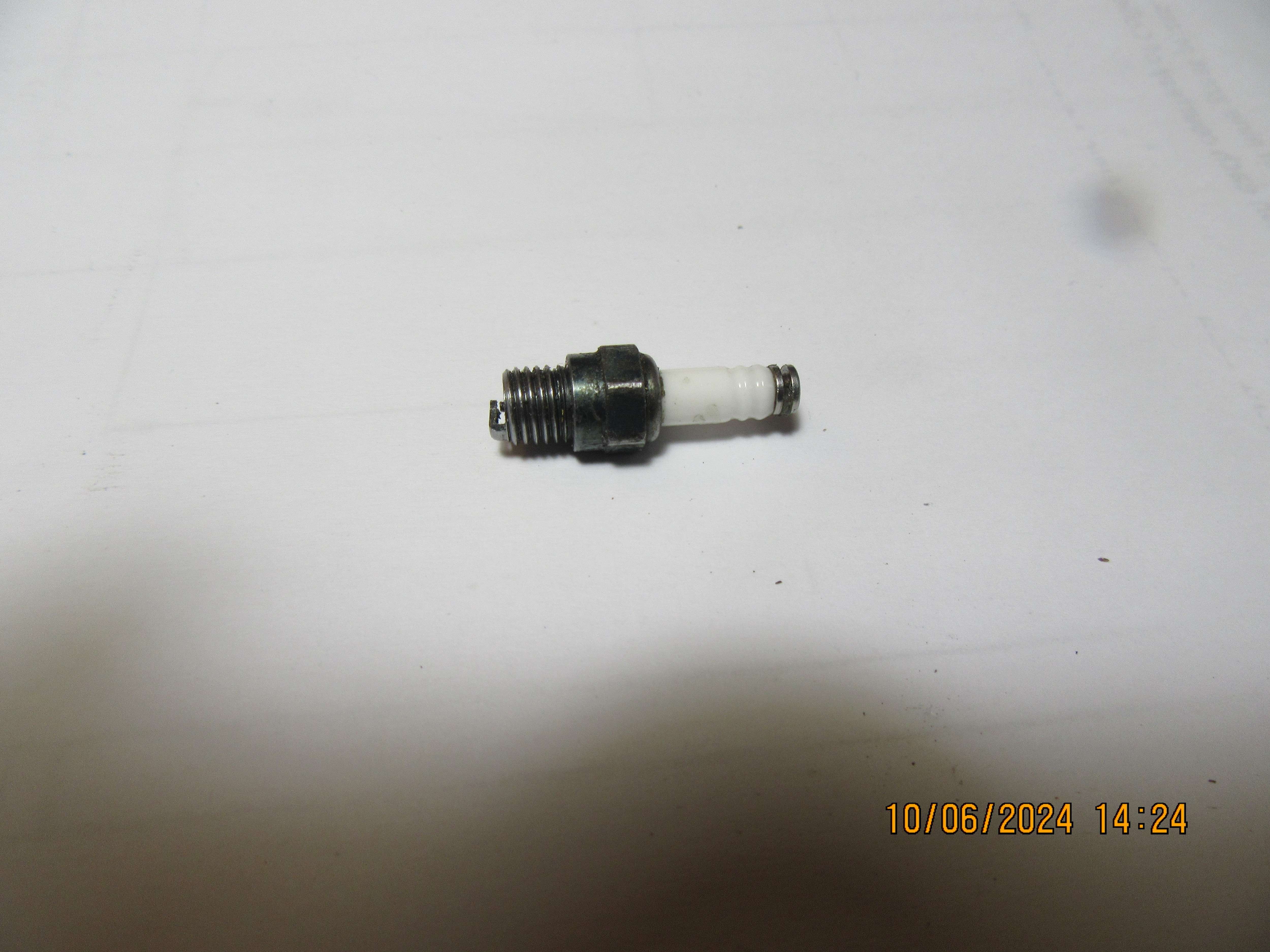
Here is a bit of an odd question. I am using a 1/4"-32 sparkplug in this engine. The end which the wire attaches to is 0.160" diameter x +/-0.075" long. Does anyone know of a sparkplug boot that fits over this size of sparkplug or is it a flat/split wire terminator that snaps over the reduced area in the center of the sparkplug terminal?
jahQ3I.jpg

IMG_4369.jpeg

Is this what you are looking for?
 
Yes, that is what I'm looking for. I think they may have them at Canadian Tire. I will have a look tomorrow.---Thanx
 

Latest posts

Back
Top