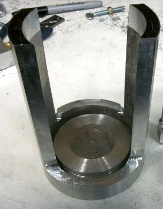
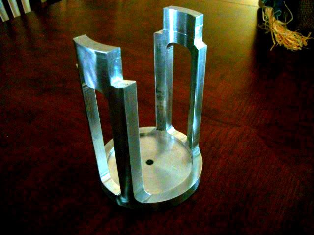
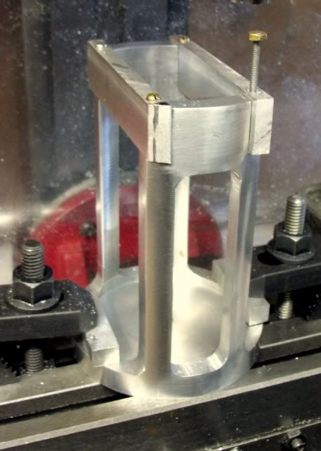
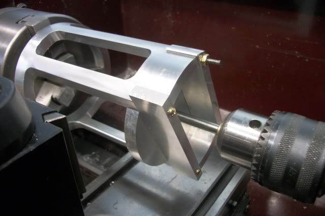
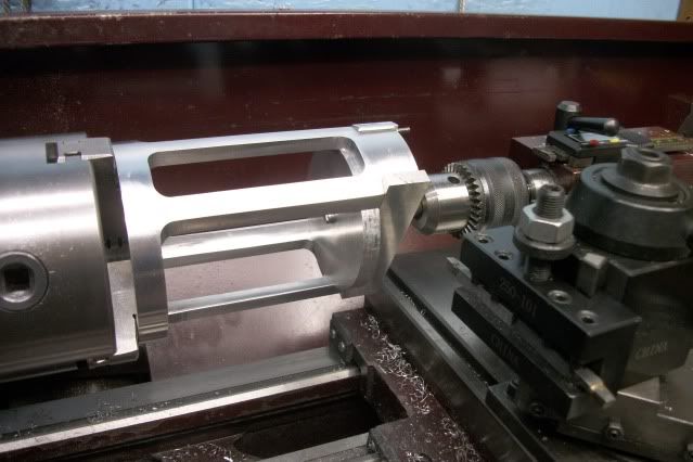
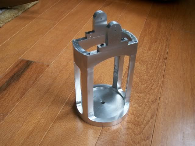
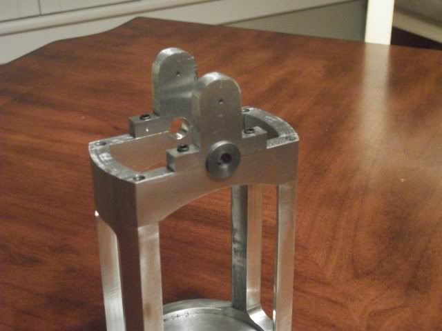
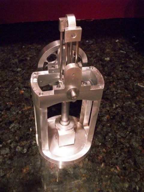
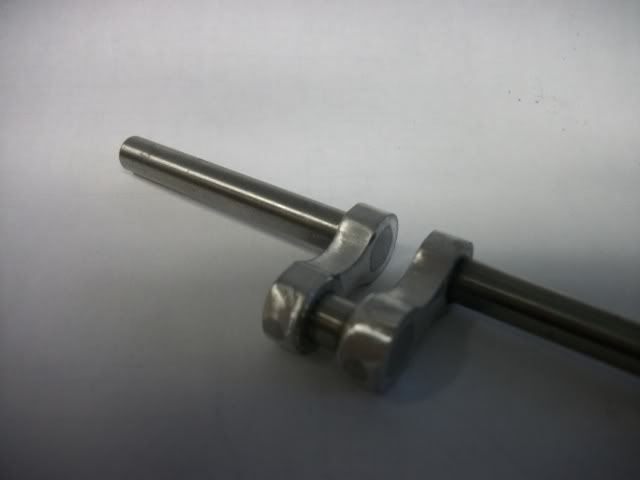
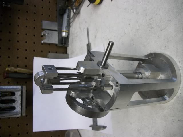
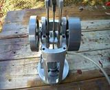
Full day in the shop today. I made lots of chip but it was very slow progress. Here is the end result:
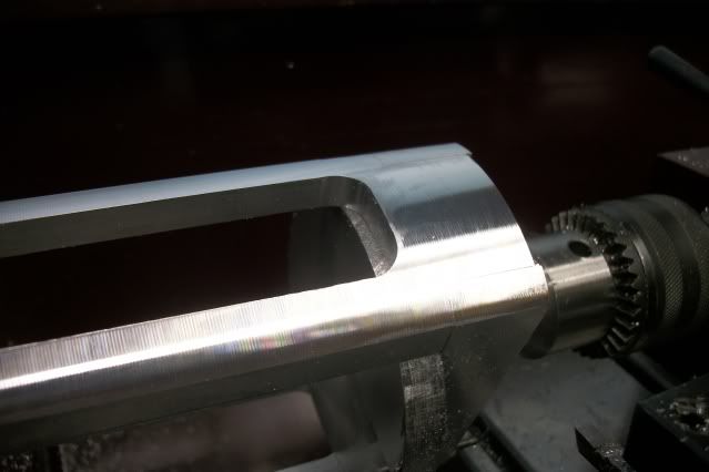
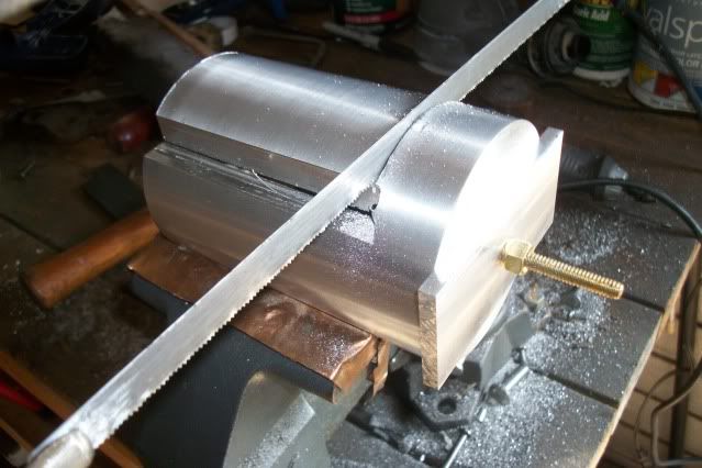
Four notches to support the bearing beams and two openings through the pipe to give the four columns.
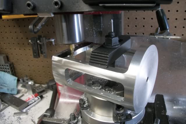
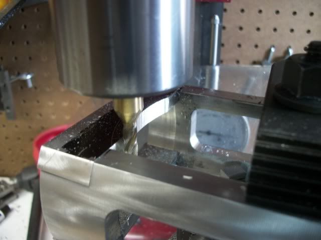
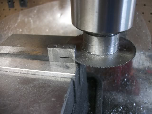
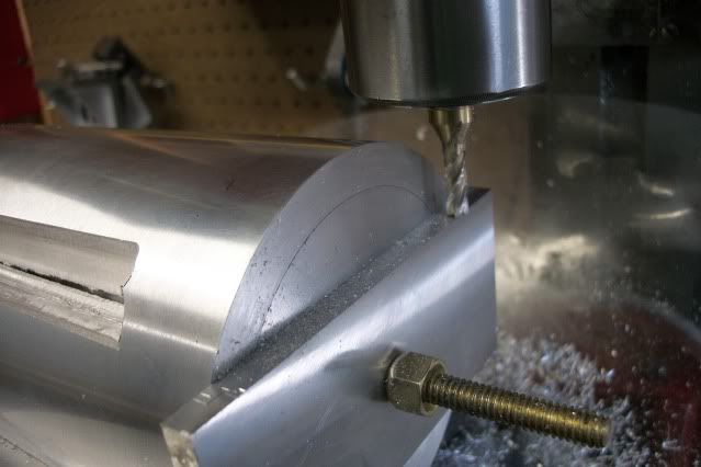
Not much to say about the notches. They are .75" by .28" but holding the pipe which is big for this mill is a bit of a challenge. Here it is held on the surface of the vise and held parallel to the X axis by the raised edge of the vise jaws spread open. A tall clamp reaches over the base to hold it down. The four notches required 4 separate setups because the "Y" axis travel is limited by the mounting of the "X" axis scale behind the table so I was unable to do two notches with one setup. There are other ways that I could have set the part and used the longer travel of the "X" axis but it would mean removing the vise.
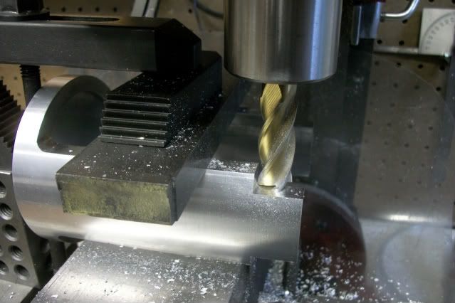
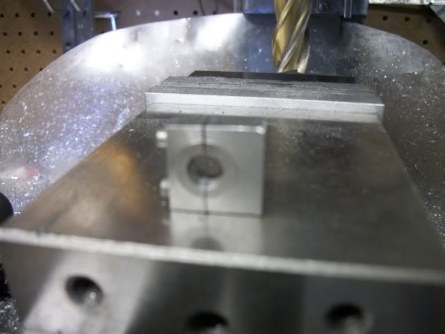
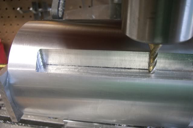
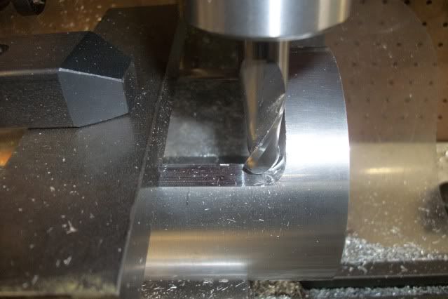
The rest of the day was used up cutting the two openings in the sides that are 1" wide and 4" tall. I had been thinking (fuzzy) that I would remove most of the waste with overlapping drilled holes but by the time I got the part clamped in the vise and held by two other hold down clamps, I had only about 1" between the part and the chuck. The only drill bit that I could get in the chuck was a centering drill so thats what I had to use to make the first entry into the hole. I could then get a 3/16" endmill in the hole. I had more overhead clearance when I switched to the R8 collet for the endmill but that is the largest endmill that I could get in the hole. I now began to make 4" long passes in a clockwise rotation around the slowly widening hole until it was the 1" wide needed.
This was a very long and slow process because I was making cuts the full depth of the material (about 3/8") but with only .030" DOC. The setup was as stable and rigid as I could get it but the top of the part was more than 4" above the table and the head was at the upper end of the "Z" travel and although I was able to find a speed/feed rate that did not produce much chatter it was slow, dull, boring, repetitive cranking of the table. It was so dull that I almost fell asleep at the job. Really! The final few passes around the perimeter of the cutout were made with a 1/2" diameter end mill to provide the filet at the top and bottom of each column.
I was not willing to risk any greater depth for fear of ruining the part. Partly because of the time already invested in this part but also because there is no replacement for it. This is a big chunk of aluminum at scrapyard prices but I didn't see any more like it at the scrapyard and way more oney that I want to spend to order new on line.
I know a picture would be nice, BUT, when I got home from the shop, I went to get something out of the trunk of the car and when I was closing the trunk lid with the hand that was also holding the camera, something happened and the camera fell from a height of over six feet to the concrete driveway.
The camera still works, as far as I can tell, but the mem chip and the batteries popped out and now the chip refuses to give up the pictures that were stored on it this afternoon. Sorry. The only evidence that I have for this day's work is the picture at the top of this post of the progress made on this part.
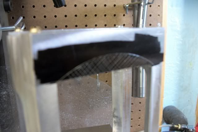
I have another chip so there will be ore interesting stuff to come. Next up are the bearing support cross beams that have a fairly large arc on the bottom edge that I don't know for sure how I will do it. Maybe the boring head, maybe a fly cutter.
Jerry




![MeshMagic 3D Free 3D Modeling Software [Download]](https://m.media-amazon.com/images/I/B1U+p8ewjGS._SL500_.png)


