You are using an out of date browser. It may not display this or other websites correctly.
You should upgrade or use an alternative browser.
You should upgrade or use an alternative browser.
Topsy Turvy Hit & Miss Engine Build
- Thread starter Harold Lee
- Start date

Help Support Home Model Engine Machinist Forum:
This site may earn a commission from merchant affiliate
links, including eBay, Amazon, and others.
Harold Lee
Well-Known Member
- Joined
- Apr 23, 2008
- Messages
- 236
- Reaction score
- 2
Thank all of you for the compliments and encouragement. It feels good turning the home stretch on this project. In my last post I said I was going to tear down the engine and paint it. But before I did I decided to run it with the muffler and oiler installed. Frankly I am very glad I did. The muffler made a lot of difference in how the engine behaved. I think the back pressure of the muffler not only made it quieter, but it "detuned" the engine enough to almost make it a sweet running engine. Based on this I would say that one should have the muffler installed before running it. Here is a video I made with the muffler and oiler installed.
Brock you asked a question regarding colors. Here is my current plans:
The engine and valve bodies will be the copper or bronze hammered finish. It helps the model look like a casting. The flywheel center will be red with a polished rim. The governor, and the crankshaft webs will be black hammered, the muffler, carb intake pipe and the oiler will be polished. The rocker arm and governor arm will be polished as well.
One additional comment to someone building this engine, the 22 tooth main gear that drives the cam is installed with 2 5-40 set screws at 90 degree angles. I had a lot of trouble with these coming loose and rotating, Additionally they buggered up the crankshaft. Rather than putting two flats on the crankshaft and then using locktite, I drilled a 1/16 hole and used a roll pin to secure it.
I'll post pictured next week when I get the engine painted and reassembled. Hope everyone has a great weekend.
Harold
Harold Lee
Well-Known Member
- Joined
- Apr 23, 2008
- Messages
- 236
- Reaction score
- 2
danstir said:Thanks for the video and the great build log. The engine sounds great!
Thank you for your comments Danstir. I really enjoyed taking everyone with me on this journey. As I promised earlier, I am posting pictures of the completed engine below. My son is a photography buff and helped me take them using his camera and a backdrop.
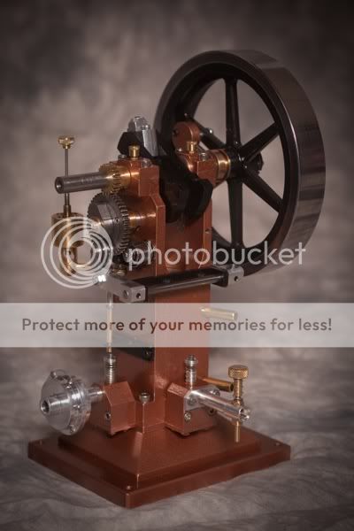
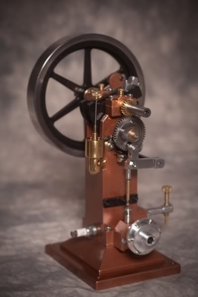
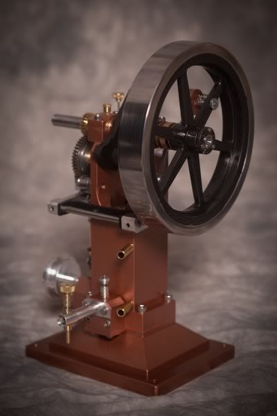
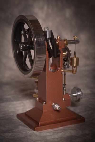
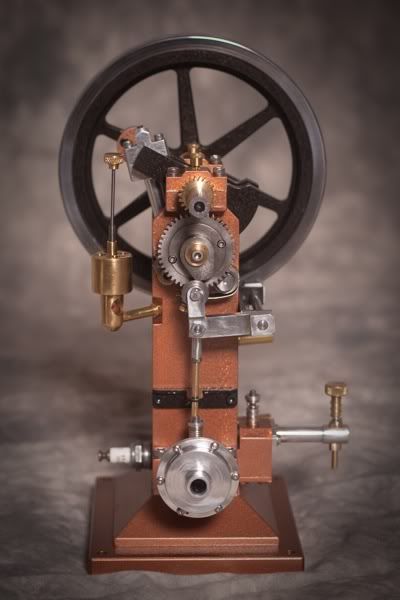
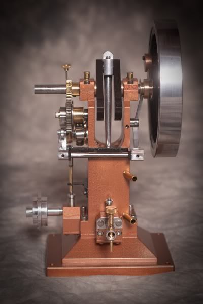
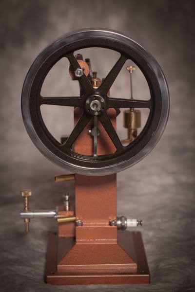
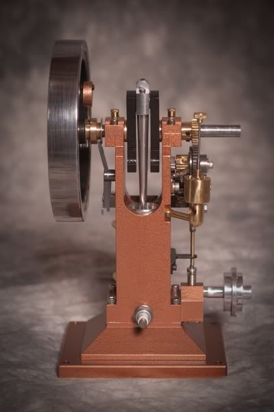
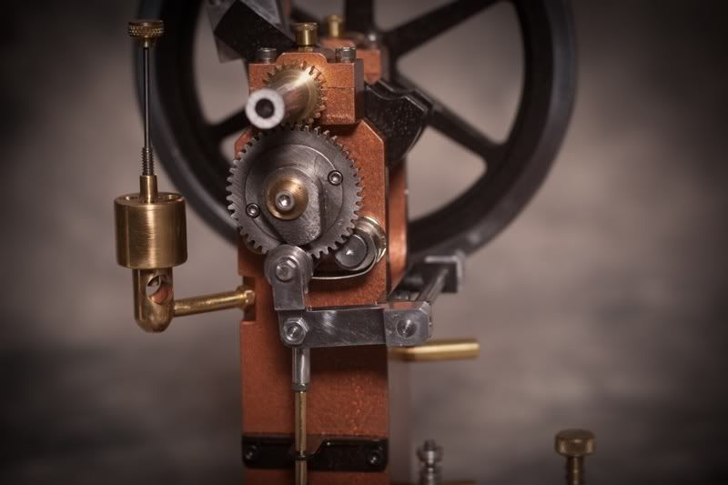
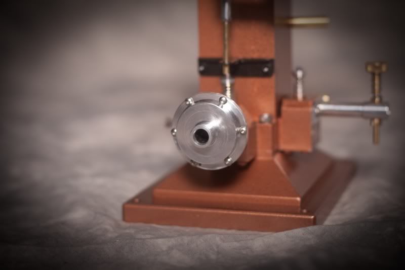
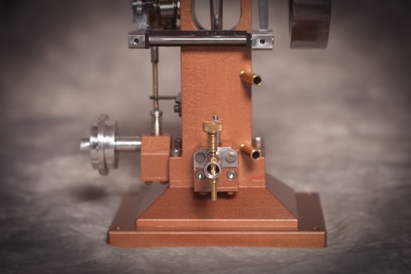
The paint is still green and I am going to let it cure for a week or so before I attempt to run again but I do have the pictures of it running "naked" so that will suffice for now. I am planning on posting a a few build comments tomorrow on a few things I learned and some deviations I made to the prints so someone can make a decision if it would be worth consideration if they build one.

$39.58
$49.99
Becker CAD 12 3D - professional CAD software for 2D + 3D design and modelling - for 3 PCs - 100% compatible with AutoCAD
momox Shop

$99.99
AHS Outdoor Wood Boiler Yearly Maintenance Kit with Water Treatment - ProTech 300 & Test Kit
Alternative Heating & Supplies

$24.99
$34.99
Bowl Sander Tool Kit w/Dual Bearing Head & Hardwood Handle | 42PC Wood Sander Set | 2" Hook & Loop Sanding Disc Sandpaper Assortment | 1/4" Mandrel Bowl Sander for Woodturning | Wood Lathe Tools
Peachtree Woodworking Supply Inc

$39.99
$49.99
Sunnytech Low Temperature Stirling Engine Motor Steam Heat Education Model Toy Kit For mechanical skills (LT001)
stirlingtechonline

$45.99
Sunnytech Mini Hot Air Stirling Engine Motor Model Educational Toy Kits Electricity HA001
stirlingtechonline

$89.99
Outdoor Wood Boiler Water Treatment Rust Inhibitor- AmTech 300 & Test Kit
Alternative Heating & Supplies

$519.19
$699.00
FoxAlien Masuter Pro CNC Router Machine, Upgraded 3-Axis Engraving All-Metal Milling Machine for Wood Acrylic MDF Nylon Carving Cutting
FoxAlien Official

$94.99
$109.99
AHS Woodmaster 4400 Maintenance Kit for Outdoor Wood Boiler Treatment
Alternative Heating & Supplies
![DreamPlan Home Design and Landscaping Software Free for Windows [PC Download]](https://m.media-amazon.com/images/I/51kvZH2dVLL._SL500_.jpg)
$0.00
DreamPlan Home Design and Landscaping Software Free for Windows [PC Download]
Amazon.com Services LLC
Harold Lee
Well-Known Member
- Joined
- Apr 23, 2008
- Messages
- 236
- Reaction score
- 2
Again I am very appreciative of all of the comments and encouragement I have received from the group. Knowing there were people "looking over my shoulder" made me take a more deliberate and methodical approach since I would need to explain and in some cases defend my choices. I very much appreciated your constructive criticisms as well and I took it to heart in an iron sharpening iron manner. Thank You!
I wanted to document in one place some of the issues I dealt with in my build as well as some problems I encountered. A number of them are documented in more detail in my narration but since most of us are "bottom line" people, I thought I would put it all in one spot and then refer back to my build narration for more detail.
The first issue is perhaps more of a philosophical discussion regarding a choice of materials used in the construction of the model. In his construction notes, Philip specifies CRS for the engine body as well as the valve bodies. I used 6061-T6 aluminum instead. I have built three IC engines in the past and all were made from aluminum and I have had very good results from a durability standpoint. I have hundreds of running hours on the engines and have never experienced a failure due to substituting aluminum for steel. One of the other mitigating factors is the equipment I have to make my engines on. My mill is a Seig X2 mini mill, and my largest lathe is a 9X20 Grizzly 4000. In my estimation both lack the rigidity to machine larger chunks of steel to any precision. I do use 12L14 CRS when I steel is required. The Topsy Turvy is a one inch bore and a two inch stroke engine, and as such tends to jump around a bit when running. I also think this is further aggravated by the unbalanced nature of the governor. The greater mass of a steel engine would probably dampen this a bit but I found after I made the muffler and put it on the engine, it tamed the engine a bit. I still think it will require clamping it down when running but based on a few comments from other builders on this board, this is not unusual even for the steel body ones.
The second issue is not totally unrelated but I found that the screws and bolts tend to loosen up while running and would recommend a small drop of blue Loctite (the non permanent threadlocker) on the screws and bolts when assembling the engine. The only place I used the red Loctite (permanent thread locker) is on the cam screw where it screws into the engine body. The design of the engine with the ignition lobe inboard and the exhaust cam lobe on the outside places a bit if a stress moment on the shaft and will tend to loosen the shaft even though it has been tightened up.
The third issue is related to an error in the plans. The drawing for the exhaust valve body specifies a 3/8-24 thread for the muffler while the drawing for the muffler specifies a 5/16-24 thread. I'll just refer those that are interested to page 9 of my build log for more details rather than rehash it here.
The fourth issue is the means of securing the flywheel to the crankshaft. The drawing calls out two setscrews a 90 degrees apart which I have found on other engines to be inadequate. I have used a tapered collet which I cover on page 8 of my log. While I did not cover it in my log, it is imperative that the key way is cut in both the crankshaft and the flywheel, collet assembly. When the slot is broached, make sure the broach cuts along the split in the collet and make sure it is screwed to the flywheel to insure alignment since part of the slot will be entirely in the collet portion and part will be entirely in the flywheel hub on the engine side. I have found that when doing final assembly, a dab of blue Loctite on the key and on the three bolts, will help keep everything secure. If this is not clear, please let me know and I will post some detailed pictures of the parts.
The fifth issue is related to the 22 tooth gear on the crankshaft. The drawing specifies two set screws at 90 degrees for securing it. I was completely unable to get this to work and it resulted in the engine loosing timing while running as well a buggering up the crankshaft. I used a 1/16 inch roll pin to secure it and it works perfectly. I was able to drill the hole through both the gear and crankshaft "in situ" by clamping the engine to my mill table and using a machinist clamp to keep the crankshaft from rotating. I then used an indicator to locate the center and drilled a 1/16 hole through both the gear hub and the crankshaft. I made my own gears and if I make another gear I will probably skip drilling and tapping the set screw holes and just use the roll pin for securing. I have removed it a number of times by just taking a 2 inch by 1/16 rod and driving the pin out.
The sixth issue is related to the bolts used to secure the valve body covers. Due to other interference issues the four holes for securing the covers are only 3/16 deep. Since bolts will probably not go to the bottom I was concerned about the number of threads holding the covers and perhaps a tendency to strip. This is further mitigated by the fact that I used alum inure for these parts instead of steel. To give me as much strength as possible, I used stainless all thread and cut four studs. this way I could take full advantage of the entire thread (I also used a bottoming tap) which I screwed into the body with some blue Loctite and then used a washer and nut on them. I mention this on page 9 of my build log in the section where I made the valve body covers.
The seventh issue is in regards to the use of piston rings. While it has been debated whether O rings are adequate instead of CI rings, there are two camps on this issue I used O rings on this engine as well as all of the other ones I have built with excellent results. A O ring will last dozens of hours of running and can be changed in about 3-4 minutes. They are cheap, and plentiful. I had two set of cast iron rings for this engine that I had purchased from Coles and they are still in my Topsy Turvy project box. At any point in the future I can make another piston and put the rings in in a few hours of work. Perhaps I'll put that on my future to do list right below the entry "organize out my sock drawer".
The eighth issue is perhaps considered a cosmetic issue but on the construction prints, the crankshaft bearing caps show a countersunk hole to serve as the oil reservoir for lubrication. I have found that these engine love to sling oil all over the place when they are run and I prefer to use grease as it will "stay put" better. I drilled and tapped the holes and used grease fittings. I think the cosmetically look better and also I like using grease better. If I was to stay with oil, I would still drill and tap and put oil cups on for cometic reasons as well.
The ninth issue is in regards to the securing of the governor catch as well and the governor weight. The drawing calls for using 1/16 cotter pins and bending them out to keep them in place. I prefer the look of bolts and I drill and tap for 2-56 bolts and use them instead. If I felt they would be subjected to a lot of wear I would make a bronze bearing but given the limited travel I think that might be a bit of overkill.
The final point is more of a self criticism than anything but If I was to repaint my engine I would probably leave the crank webs natural unfinished steel rather than the hammered black. I was hoping the black would set off the polished connecting rod but not sure I was successful.
FUTURE WORK
Wooden base that would integrate the ignition parts in it.
Small gas tank that would mount to the engine under the flywheel that would have a glass end for showing fuel level similar to my previous engines.
A cooling tower that would not look like a salvaged hairspray can(not that there is anything wrong with that ) that would work and add to the aesthetics of the model.
Excuse me.... but I have a steam tractor to finish....
SOME FINAL THOUGHTS AND BUILD COMMENTS
I wanted to document in one place some of the issues I dealt with in my build as well as some problems I encountered. A number of them are documented in more detail in my narration but since most of us are "bottom line" people, I thought I would put it all in one spot and then refer back to my build narration for more detail.
The first issue is perhaps more of a philosophical discussion regarding a choice of materials used in the construction of the model. In his construction notes, Philip specifies CRS for the engine body as well as the valve bodies. I used 6061-T6 aluminum instead. I have built three IC engines in the past and all were made from aluminum and I have had very good results from a durability standpoint. I have hundreds of running hours on the engines and have never experienced a failure due to substituting aluminum for steel. One of the other mitigating factors is the equipment I have to make my engines on. My mill is a Seig X2 mini mill, and my largest lathe is a 9X20 Grizzly 4000. In my estimation both lack the rigidity to machine larger chunks of steel to any precision. I do use 12L14 CRS when I steel is required. The Topsy Turvy is a one inch bore and a two inch stroke engine, and as such tends to jump around a bit when running. I also think this is further aggravated by the unbalanced nature of the governor. The greater mass of a steel engine would probably dampen this a bit but I found after I made the muffler and put it on the engine, it tamed the engine a bit. I still think it will require clamping it down when running but based on a few comments from other builders on this board, this is not unusual even for the steel body ones.
The second issue is not totally unrelated but I found that the screws and bolts tend to loosen up while running and would recommend a small drop of blue Loctite (the non permanent threadlocker) on the screws and bolts when assembling the engine. The only place I used the red Loctite (permanent thread locker) is on the cam screw where it screws into the engine body. The design of the engine with the ignition lobe inboard and the exhaust cam lobe on the outside places a bit if a stress moment on the shaft and will tend to loosen the shaft even though it has been tightened up.
The third issue is related to an error in the plans. The drawing for the exhaust valve body specifies a 3/8-24 thread for the muffler while the drawing for the muffler specifies a 5/16-24 thread. I'll just refer those that are interested to page 9 of my build log for more details rather than rehash it here.
The fourth issue is the means of securing the flywheel to the crankshaft. The drawing calls out two setscrews a 90 degrees apart which I have found on other engines to be inadequate. I have used a tapered collet which I cover on page 8 of my log. While I did not cover it in my log, it is imperative that the key way is cut in both the crankshaft and the flywheel, collet assembly. When the slot is broached, make sure the broach cuts along the split in the collet and make sure it is screwed to the flywheel to insure alignment since part of the slot will be entirely in the collet portion and part will be entirely in the flywheel hub on the engine side. I have found that when doing final assembly, a dab of blue Loctite on the key and on the three bolts, will help keep everything secure. If this is not clear, please let me know and I will post some detailed pictures of the parts.
The fifth issue is related to the 22 tooth gear on the crankshaft. The drawing specifies two set screws at 90 degrees for securing it. I was completely unable to get this to work and it resulted in the engine loosing timing while running as well a buggering up the crankshaft. I used a 1/16 inch roll pin to secure it and it works perfectly. I was able to drill the hole through both the gear and crankshaft "in situ" by clamping the engine to my mill table and using a machinist clamp to keep the crankshaft from rotating. I then used an indicator to locate the center and drilled a 1/16 hole through both the gear hub and the crankshaft. I made my own gears and if I make another gear I will probably skip drilling and tapping the set screw holes and just use the roll pin for securing. I have removed it a number of times by just taking a 2 inch by 1/16 rod and driving the pin out.
The sixth issue is related to the bolts used to secure the valve body covers. Due to other interference issues the four holes for securing the covers are only 3/16 deep. Since bolts will probably not go to the bottom I was concerned about the number of threads holding the covers and perhaps a tendency to strip. This is further mitigated by the fact that I used alum inure for these parts instead of steel. To give me as much strength as possible, I used stainless all thread and cut four studs. this way I could take full advantage of the entire thread (I also used a bottoming tap) which I screwed into the body with some blue Loctite and then used a washer and nut on them. I mention this on page 9 of my build log in the section where I made the valve body covers.
The seventh issue is in regards to the use of piston rings. While it has been debated whether O rings are adequate instead of CI rings, there are two camps on this issue I used O rings on this engine as well as all of the other ones I have built with excellent results. A O ring will last dozens of hours of running and can be changed in about 3-4 minutes. They are cheap, and plentiful. I had two set of cast iron rings for this engine that I had purchased from Coles and they are still in my Topsy Turvy project box. At any point in the future I can make another piston and put the rings in in a few hours of work. Perhaps I'll put that on my future to do list right below the entry "organize out my sock drawer".
The eighth issue is perhaps considered a cosmetic issue but on the construction prints, the crankshaft bearing caps show a countersunk hole to serve as the oil reservoir for lubrication. I have found that these engine love to sling oil all over the place when they are run and I prefer to use grease as it will "stay put" better. I drilled and tapped the holes and used grease fittings. I think the cosmetically look better and also I like using grease better. If I was to stay with oil, I would still drill and tap and put oil cups on for cometic reasons as well.
The ninth issue is in regards to the securing of the governor catch as well and the governor weight. The drawing calls for using 1/16 cotter pins and bending them out to keep them in place. I prefer the look of bolts and I drill and tap for 2-56 bolts and use them instead. If I felt they would be subjected to a lot of wear I would make a bronze bearing but given the limited travel I think that might be a bit of overkill.
The final point is more of a self criticism than anything but If I was to repaint my engine I would probably leave the crank webs natural unfinished steel rather than the hammered black. I was hoping the black would set off the polished connecting rod but not sure I was successful.
FUTURE WORK
Wooden base that would integrate the ignition parts in it.
Small gas tank that would mount to the engine under the flywheel that would have a glass end for showing fuel level similar to my previous engines.
A cooling tower that would not look like a salvaged hairspray can(not that there is anything wrong with that
Excuse me.... but I have a steam tractor to finish....
Very, very nice engine Harold. It looks good, runs good, and sounds good!!! You sir have built something to be very proud of.----Brian
fcheslop
Well-Known Member
Hi Harold,many thanks for the info it will be very useful as Topsy is my next i.c build.Will you please post some detailed pics of the flywheel collet as I'm not quite certain and id like to know :big:.The finished engine is truly magnificent and a tribute to you're skill
Good luck finishing the traction engine build
best wishes Frazer
Good luck finishing the traction engine build
best wishes Frazer
Very nice.
Sometime just for fun you should make a shorter piston to reduce the compression ratio. You might find the engine becomes a lot less inclined to bounce around when it fires with the lower compression ratio. four to 1 might not be too bad for this style of engine.
Jim
Sometime just for fun you should make a shorter piston to reduce the compression ratio. You might find the engine becomes a lot less inclined to bounce around when it fires with the lower compression ratio. four to 1 might not be too bad for this style of engine.
Jim
Harold Lee
Well-Known Member
- Joined
- Apr 23, 2008
- Messages
- 236
- Reaction score
- 2
fcheslop said:SNIP>>> Will you please post some detailed pics of the flywheel collet as I'm not quite certain and id like to know SNIP>>>
best wishes Frazer
Frazer - I will try to give you more detail. If this is still not clear please let me know what is lacking in my explanation/pictures and I'll try to fill it in. First off, I am probably misleading you by calling this a flywheel collet and that might be confusing. The books call it a "flywheel hub taper lock". I can never think of that term when I am typing so I just call it a collet. The lathe turning for the taper lock as well as the flywheel hub are documented in the build log on page 8 about 2/3 of the way down. This shows the turning of the 4 degree taper on both parts.
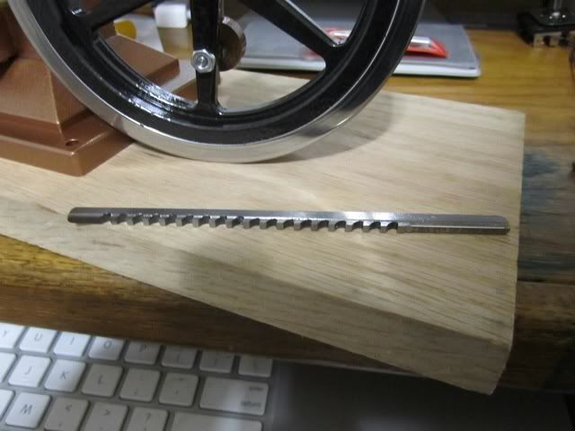
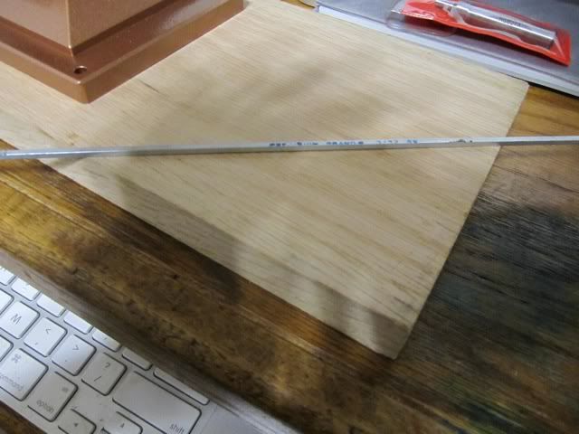
To cut the keyway, I have a 3/32 broach, a 3/32 end mill, and I have purchased some 3/32 keystock from Enco although I could make the key on the mill. It is just too easy to purchase it by the foot. The mill is used to cut the keyway slot in the crankshaft. I do not show this step but here is a picture of it. This is done to the print.
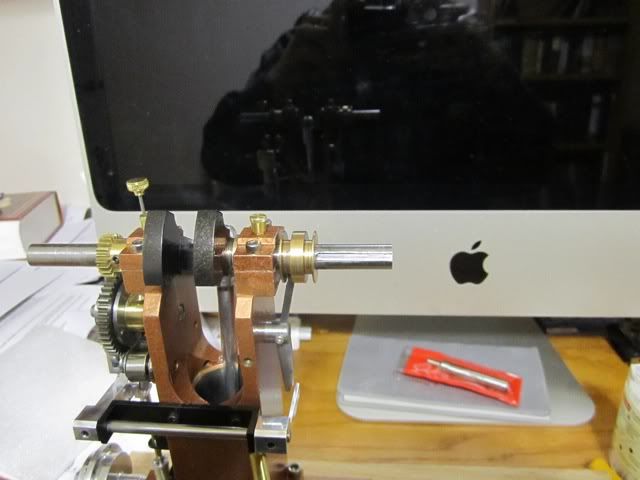
The 3/32 Broach...
The 3/32 keystock
Additionally, I have made a hub for the broach out of CRS...
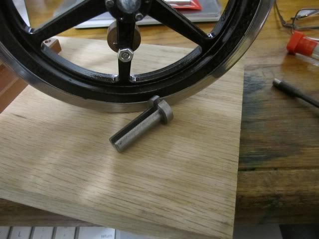
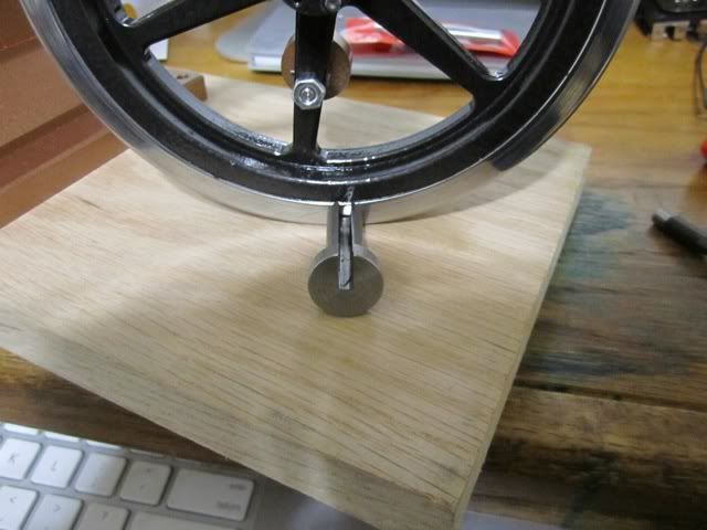
At this point I put the taper lock hub in the flywheel and put the three bolts in it to make sure the registration of the hub to the flywheel is correct but I do not tighten the bolts down as they would squeeze the .375 diameter hole and I could not get the broach hub in.
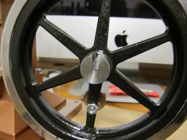
Then I insert the broach into the flywheel. Don't forget a generous bit of cutting oil..
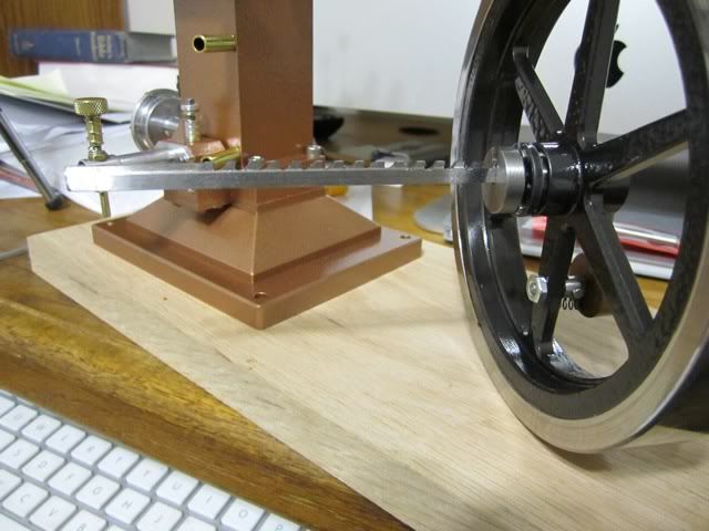
Using my arbor press, I just push the broach through... did I mention some cutting oil? :-;
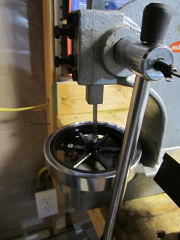
Here are the parts after this operation...
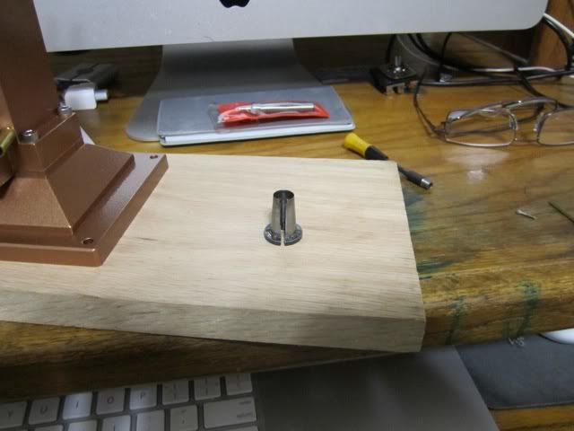
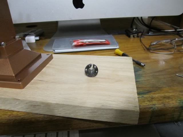
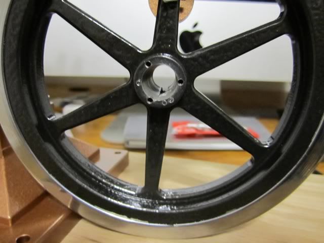
At this point everything is done and it is a matter of assembling everything with the key and giving it a good snugging up. As I mentioned in my build notes, use some blue Loctite on the three bolts to keep them tight.
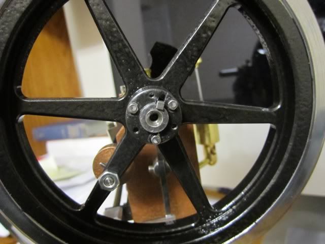
Hope this answers your questions. Please let me know if you need additional info... Good luck...
Harold
el gringo
Well-Known Member
- Joined
- Aug 30, 2010
- Messages
- 333
- Reaction score
- 175
Harold;
A pic of a Topsy is on the inside front cover of current MEB magazine. It has a "cooling tower' of sorts.
A heavy hardwood base with a larger footprint might help mitigate the 'jumping'.
Ray M
fcheslop
Well-Known Member
Hi Harold,Many thanks for taking the time to explain the penny eventually dropped :big:.
best wishes Frazer
best wishes Frazer
- Joined
- Jul 3, 2010
- Messages
- 278
- Reaction score
- 10
Hi Harold,
Congratulations (a little late :-[ ), it runs and looks beautiful :bow: :bow: :bow: :bow:
Thans for taking the time to write-up the build, I will use the part of turing the crank these days to start to make mine.
Mmmm.....steam tractor??? Have some pictures, I really like steam tractors (and pictures) ;D
Regards Jeroen
RonW
Well-Known Member
Super job Harold. Two questions, the video has disappeared and two, can the photobucket logs be removed so you can see your beautiful work. Half the photos have the crucial part covered. Otherwise, excellent!!
RonW
RonW
Similar threads
- Replies
- 83
- Views
- 10K
- Replies
- 8
- Views
- 1K
- Replies
- 0
- Views
- 303


