Tips for Arduno software for Rotary Table Controllers

Home Model Engine Machinist Forum

Help Support Home Model Engine Machinist Forum:

This site may earn a commission from merchant affiliate links, including eBay, Amazon, and others.
WOW

Thanks Rod !

I have the SainSmart LCD. I will see if it is adaptable, if not I will get the FreeTronics, I like those buttons better anyway.

Many Thanks

Scott

Good luck with it Scott. I connected a NEMA 23 stepper up to my 90:1 Vertex 6" rotary table today and with a few tweaks, it works!

Initially, I was missing a few steps so I experimented with changing the Timer delay and slowed it down to get more torque. I also swapped the values around for the Direction.

Code:
#define CLOCKWISE     LOW
#define ANTICLOCKWISE HIGH
#define TIMER_DELAY 80

I took a few photos of how I attached the stepper to the table so will post them up later this evening. First time I broached a keyway and it worked nicely.

I just held the Stepper in my hands at this stage. The next "step" is to make the mount to attach it permanently. I was never sure if the stepper I had was strong enough to drive the table.
 
Photo time.

First all of the hardware
DSC_5226_zpsfebad2a1.jpg


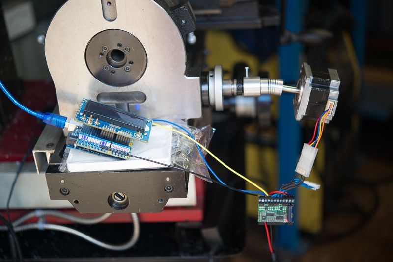
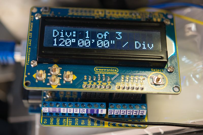
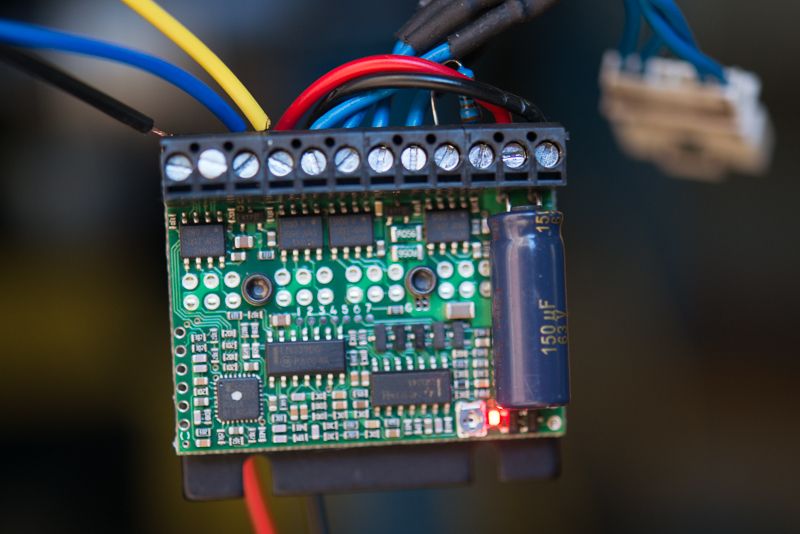
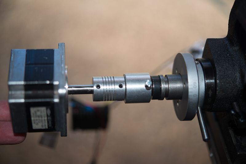
The Arduino and Freetronics Terminal Shield with the LCD display on top. The Gecko GX251 Micro drive stepper driver. It is being powered by a 19 volt laptop power supply. You can see I have used a flexible coupler for the stepper motor.

DSC_5227_zpsd6a00d74.jpg


In business mode!

THis is the Gecko controller

DSC_5230_zps39240784.jpg


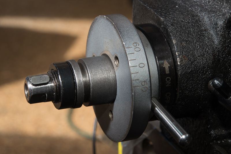
Here is the 6" Rotary table with the handle removed
DSC_5235_zpsa5f7a299.jpg


The shaft is 12mm and the keyway is 4mm. The diameter of the backplate is 56mm. I have some 55mm round stock here that will be perfect to make the mount from. You can see the plate at the back has some M5 threaded holes in it. I made these on a PCD of 32mm.

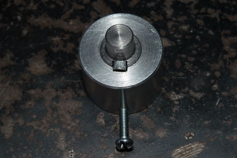
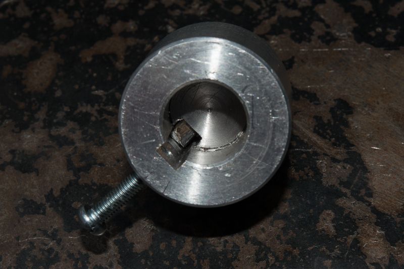
So I decided if I made a 20mm long collar with a 12mm bore, I could broach a keyway in it.

Then all I'd need to do would be to make a 20mm long adapter shaft that was M12 at one end (with a keyway milled in it) and 8mm to match the stepper shaft at the other.

Sorry, but when I checked my stock of keys, I did not have a 4mm one so I had to file one down and I ended up pressing it in (it's tight!) so no photo of the adapter shaft but you'll get the idea.

DSC_5242_zps25f32eb2.jpg


I did not bother to add a set screw here as once its assembled, it can't fall apart. I have to get M3 set screw though!

And here's the other end that will mate up with the rotary table shaft.

DSC_5241_zpsbe9eab30.jpg


So here is it all in place!

DSC_5231_zpsb959e157.jpg


Initially, I made the collar out of 19mm dia aluminium and thought there might not be enough meat for the keyway so I remade it out of 25mm. I should have used the original one! I've since turned the collar down to 20mm to make it easier to gain clearance for the adapter.

I've measured up the adapter and will draw it up properly, but it looks pretty straightforward. It will need a slot in it to reach the various set screws.
 
Success !!

It works with the SainSmart LCD shield. I had to change my step and direction wires to 1&2 from 2&3. I also had to change the timer delay, 50 worked but I changed it to 60 for a little more margin of safety. I also added more delay to the screensaver(30) 10 sec was too short, the screen would blank before it finished making some moves requiring 2 button presses to go to the next position. I set div to 1 and timed it, with this power supply 21 sec. for 90 turns of the motor.

You mentioned something about moving the cursor and entering values, was that something that will be implemented or should work now?
If it should work now, either it does not or I can't figure it out.
All the buttons seem to do what they are supposed to , up , down , left , right and select.

This is more than sufficient for my needs , just curious about the cursor.

Very well done sir !! Many thanks !

Scott

EDIT

I just played with the Form sketch, The cursor moves there and I can change values. ???
 
Success !!

It works with the SainSmart LCD shield. I had to change my step and direction wires to 1&2 from 2&3. I also had to change the timer delay, 50 worked but I changed it to 60 for a little more margin of safety. I also added more delay to the screensaver(30) 10 sec was too short, the screen would blank before it finished making some moves requiring 2 button presses to go to the next position. I set div to 1 and timed it, with this power supply 21 sec. for 90 turns of the motor.

You mentioned something about moving the cursor and entering values, was that something that will be implemented or should work now?
If it should work now, either it does not or I can't figure it out.
All the buttons seem to do what they are supposed to , up , down , left , right and select.

This is more than sufficient for my needs , just curious about the cursor.

Very well done sir !! Many thanks !

Scott

EDIT

I just played with the Form sketch, The cursor moves there and I can change values. ???

is the complete working code posted somewhere?
 
Great Rod! Thm:

I have a problem with the keys, how and where to make it right?

Thank you!
 
Rod, is there a data entry or menu library you are using, or is this something you are writing? Is it, or will it be available? It sounds like a very useful library.

Ron, sorry, I missed this. I'd tried writing my own and then found a couple of promising libraries but they refused to play together. I dropped one and bave posted all of the required resources on post #20
http://www.homemodelenginemachinist.com/showpost.php?p=261783&postcount=20

So read on from there.
 
Success !!

It works with the SainSmart LCD shield. I had to change my step and direction wires to 1&2 from 2&3. I also had to change the timer delay, 50 worked but I changed it to 60 for a little more margin of safety. I also added more delay to the screensaver(30) 10 sec was too short, the screen would blank before it finished making some moves requiring 2 button presses to go to the next position. I set div to 1 and timed it, with this power supply 21 sec. for 90 turns of the motor.

You mentioned something about moving the cursor and entering values, was that something that will be implemented or should work now?
If it should work now, either it does not or I can't figure it out.
All the buttons seem to do what they are supposed to , up , down , left , right and select.

This is more than sufficient for my needs , just curious about the cursor.

Very well done sir !! Many thanks !

Scott

EDIT

I just played with the Form sketch, The cursor moves there and I can change values. ???

Scott, awesome that you have got this up and running with so few changes. I was kinda hoping the keyboards were compatible with each other.

I had thought of disabling the screen saver on entry to the godivide () function and reenabling on exit but your solution is probably better. It did not annoy me until i got out in the shed.

Glad you sorted out the cursor as I didn't have a clue what I had said.
 
Great Rod! Thm:

I have a problem with the keys, how and where to make it right?

Thank you!

The Freetronics and SainsSmart are an analog keyboard so they use a single analog port with a series of resistors that alter the voltage to a known value when a key is pressed. Freetronics has a good description of how this works and the wiring diagram for them.

If your keys are not analog keys then it won't work. If they are analog keys, search in the LCD library code for call to an analog read and review the code there. Change it to values that suit you. Or make your own keyboard and use the resistor values Freetronics uses. You can change the analog port when you create the LCD variable.
 
You can change the analog port when you create the LCD variable.

This is what I use.
Butt.jpg

At Chuck first version worked like this:

if (adc_key_in < 60) return btnRIGHT;
if (adc_key_in < 200) return btnUP;
if (adc_key_in < 400) return btnDOWN;
if (adc_key_in < 880) return btnLEFT;
if (adc_key_in < 950) return btnSELECT;

My C ++ is bad so now I do not know where I change the value in your program.

Thanks for your help!

Assuming you have made your own keyblard as per the circuit shown, and are not using a pre made shield, you could replace your resistors with the values shown here
http://www.freetronics.com.au/pages/16x2-lcd-shield-quickstart-guide#.VOFbeZt47MI

That would provide compatability with the Sainsmart and Freetronics boards which might be a good thing.
 
Ok, modifying the code to use different resistor values is not simple.

In LCD.cpp, this code needs to be modified
// Button mapping table generated by genlookup.c
static unsigned char const buttonMappings[] PROGMEM = {
2, 0, 0, 0, 3, 0, 0, 0, 0, 4, 4, 0, 0, 0, 0, 1,
1, 0, 0, 0, 0, 0, 5, 5, 0, 0, 0, 0, 0, 0, 0, 0
};

It is generated by a separate program (genlookup.c) designed to run on a desktop PC. The program is here and is part of the LCD library I linked to in post #20.
https://github.com/rweather/arduinolibs/blob/master/gen/genlookup.c

So what you have to do is to establish the values returned by each button by an analog read, Then modify genlookupc.c

and change these values

Code:
#define LCD_BUTTON_VALUE_GAP    10
#define LCD_BUTTON_RIGHT_VALUE  0
#define LCD_BUTTON_UP_VALUE     145
#define LCD_BUTTON_DOWN_VALUE   329
#define LCD_BUTTON_LEFT_VALUE   505
#define LCD_BUTTON_SELECT_VALUE 741

Then compile and run the program and insert the output into LCD.cpp

You could run this generator on an Arduino if you modify genlookup.c to use serial.print to print it to the serial port.
 
Just added a new feature for jogging.

Left and right button turn the table either direction while the button is held down.
Up and down button moves left or right 1 single step.

Initially I though this code was not working with my microstep drive but if you hold you hand on the stepper, you could just feel the slightest bump (angle is 0.8 seconds) so I changed it to 10 steps. eventually, I will make this user configurable.

Give me a few more days to add a bit more to it before I post up the code.

Speed control, home position memory, and enter a dividing angle in DMS still to come.
 
Assuming you have made your own keyblard as per the circuit shown, and are not using a pre made shield, you could replace your resistors with the values shown here
http://www.freetronics.com.au/pages/16x2-lcd-shield-quickstart-guide#.VOFbeZt47MI

That would provide compatability with the Sainsmart and Freetronics boards which might be a good thing.

Resistance values are the same on my schedule as well as on http://www.freetronics.com.au/pages/16x2-lcd-shield-quickstart-guide#.VOFbeZt47MI

I think the problem was the length of the wires that were not coax so that the issue is resolved one capacitor.

It would be good to add in parallel to each key by a capacitor cca.100nF.

lcd_button_ladder.png

Thanks for your help!

Btw. It would be good to do (do not know his name) and this possibility

zzzzz.jpg
 
Hi guys, I've attached an update for my faithful beta testers. The code has been changed quite a lot so beware any bugs!

We now have the following features:
1. Menu has changed to make it flatter. To open a menu procedure, press the up or down arrows
2. Pressing Select exits a procedure.
3. Divide feature entering # of divisions
4. Divide feature by entering Degrees, Minutes, Seconds. Cursor left and right along the field and change digits with the up and down buttons. Press Select to move to operation
5. Jog function. Rotary Table operates continuously while the left or right button is held down. Up and down button moves stepper NUMBER_JOG_STEPS each button press. This should let you get a perfect setup if say you wanted to drill holes in the side of a hex bar.

The other feature I want to add is the ability to remember a home position and be able to return to that position by simply pressing a button. That needs a bit of thought as the distance from home needs to be maintained within the ISR procedure.

View attachment RotaryTableChuck2.zip
 
Back
Top