I'm a bit bored today. Not a lot, but winter's coming. I've played with my v-twin engine until I've reached a point where it will run like crazy at mid range speeds, but doesn't respond well to slowing down, not for that matter to speeding up. I think I am going to put it away for a while, and come back to it later. I have enough stock "in house" to build a pair of 4 1/2" flywheels. I would like to run a 1" bore, not because it would have more power, but because at 1" bore I can use a 3/8" thread sparkplug which I can purchase from a local automotive store. If I use a 3/4" bore, then I can only fit in a 1/4" sparkplug. I have my own complete set of 24 DP gear cutters, and may opt to use a 25 tooth and a 50 tooth set of timing gears. Probably go for a 1 1/4" stroke, maybe 1 3/8". I would build my own mixer (carburetor). Air cooled is the easiest route for me to go, but I would design it to also use a water jacket, because since I sell these drawings I am sure people would like to have a choice. I don't think I would put a fan on this one, because if the hit and miss cycles are working properly, the engine will pump enough air through during the miss cycles that it will run pretty cool anyways. Brass, in any size, has become so terribly expensive that other than some trim pieces the engine would primarily be made from steel and aluminum. Cast iron cylinder sleeve and cast iron piston. Paint is still cheap as dirt, and if done properly can really give some eye appeal to an engine. I won't be cutting metal for a while yet, but I get excited thinking about the design stage.
You are using an out of date browser. It may not display this or other websites correctly.
You should upgrade or use an alternative browser.
You should upgrade or use an alternative browser.
Time for a new Horizontal Hit and Miss engine
- Thread starter Brian Rupnow
- Start date

Help Support Home Model Engine Machinist Forum:
This site may earn a commission from merchant affiliate
links, including eBay, Amazon, and others.
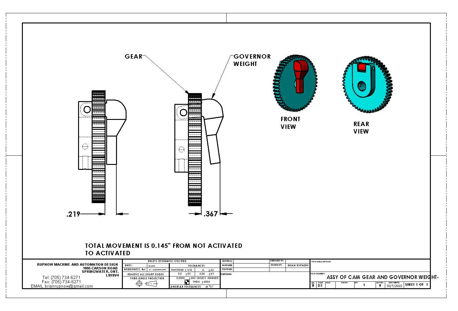
After having a good look at the cam gear mounted governor, I prefer the Breisch Olds style to the Chinese style of governor. The Breisch style has ample movement at 0.148" and looks simpler to me.

Last edited:
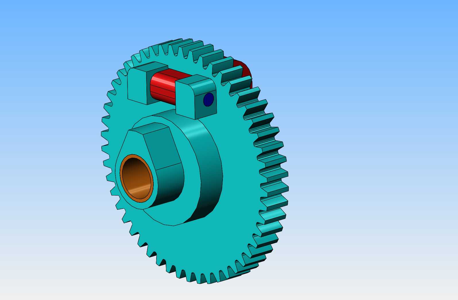
The cam gear will be a bit complex. It will have the mounting points for the governor pivot shaft, a section of hub, and a cam machined onto the face of the hub. With an oilite bushing pressed into the center, it can be supported on the side of the engine frame by a shoulder bolt. There will be no camshaft, as the intake valve will be atmospheric and not depend on a cam to open it.

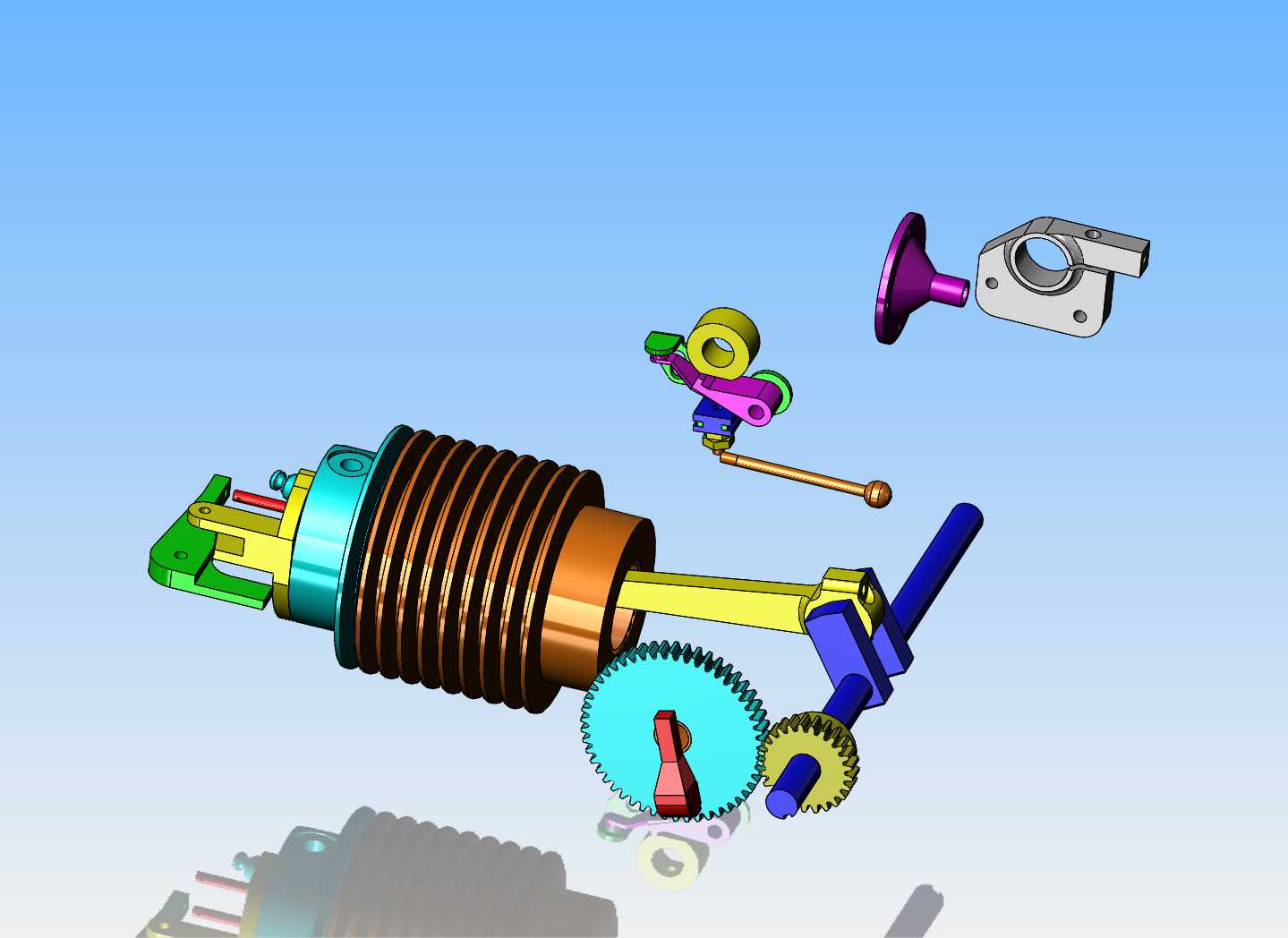
By going through the past 13 years of models, I can find enough ready made models of parts to get a very good start on a new engine. The newest part on here is the governor lever and it's associated gear, and the crazy looking air cooled cylinder.

Will be following along, again, Keep up the great work, love the problem solving.
Cheers
Andrew
Cheers
Andrew
How about a vertical?

$26.89
$34.99
Peachtree Woodworking Supply Bowl Sander Tool Kit w/Dual Bearing Head & Hardwood Handle, 42 Pieces Wood Sander Set, 2 Hook & Loop Sanding Disc Sandpaper Assortment, 1/4 Mandrel Bowl Sander
Peachtree Woodworking Supply Inc

$19.15
$29.95
Competition Engine Building: Advanced Engine Design and Assembly Techniques (Pro Series)
MBC Inc.

$599.00
$649.00
FoxAlien Masuter Pro CNC Router Machine, Upgraded 3-Axis Engraving All-Metal Milling Machine for Wood Acrylic MDF Nylon Carving Cutting
FoxAlien Official
![DreamPlan Home Design and Landscaping Software Free for Windows [PC Download]](https://m.media-amazon.com/images/I/51kvZH2dVLL._SL500_.jpg)
$0.00
DreamPlan Home Design and Landscaping Software Free for Windows [PC Download]
Amazon.com Services LLC

$45.99
Sunnytech Mini Hot Air Stirling Engine Motor Model Educational Toy Kits Electricity HA001
stirlingtechonline

$99.99
AHS Outdoor Wood Boiler Yearly Maintenance Kit with Water Treatment - ProTech 300 & Test Kit
Alternative Heating & Supplies

$37.38
$49.99
Becker CAD 12 3D - professional CAD software for 2D + 3D design and modelling - for 3 PCs - 100% compatible with AutoCAD
momox Shop

$49.95
$55.99
DjuiinoStar Hot Air Stirling Engine Assembly Kit: Spend 30 Minutes to Build Your Own Stirling Engine
djuiinostar
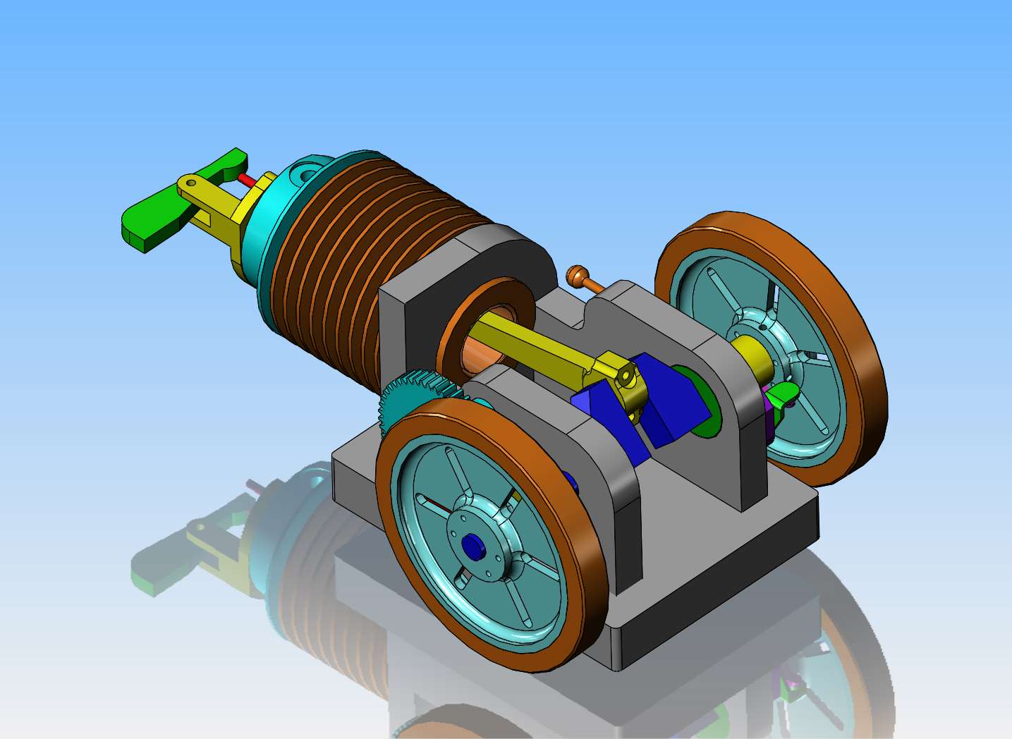
Well, at the end of the day, I have everything except exhaust, carburetor, and the actual components that make it hit and miss. The exhaust and carb will be mainly copy and paste operations. Vietti--It's horizontal mainly because I like the look of a horizontal more than a vertical. I've managed to kill a whole day here. Good wife is away to a funeral today and won't be home until later this evening. Time to go find a good book to read and grab some supper now.

Got a start on the hit and miss mechanism. Have to go and get some breakfast now and see what chores my wife has set up for me pre-thanksgiving.
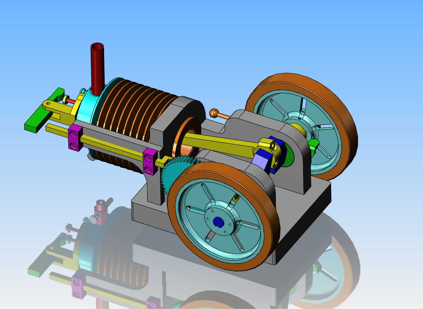

So, that's enough playing for one day.
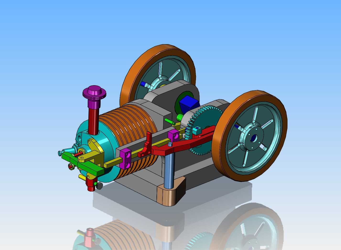

I had to do a bit of rearranging. I had the large cam gear above the centerline of the crankshaft so it would line up with the top valve on the cylinder head, which is the exhaust. I didn't like the look of it though, because too much gear was showing. Allright--I'll move the big gear to a point below the crankshaft, and line it up with the bottom intake valve---and then I'll be tricky and put the rocker arm and mounts on the cylinder head at an angle so that it will still operate the exhaust valve. That pretty well does it for the major design. A ton of bolt clearance holes and threaded holes to be added, but that is fairly simple stuff. I haven't thought much about a gas tank location yet, but will probably do that next.
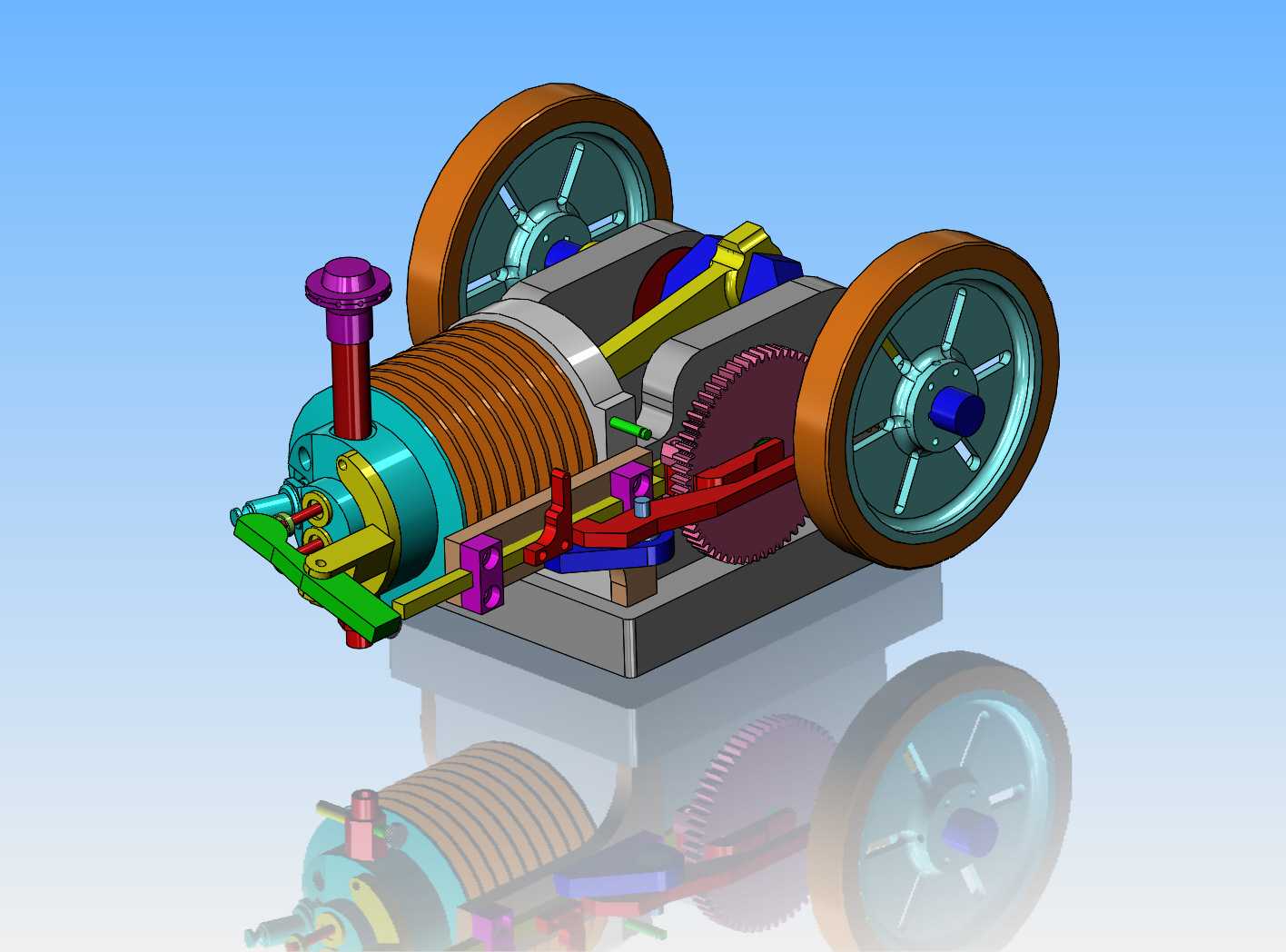

I've decided to make the 60 tooth gear and the cam as two separate pieces and then pin and solder them together. This is the absolute fastest way to make a cam. When there is no need to make a machined flank on the cam (because the cam follower is a bearing) I can rattle one of these off using first the lathe, then the rotary table on my milling machine in less than an hour.

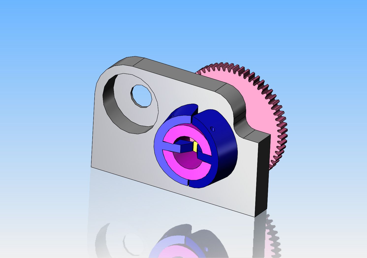
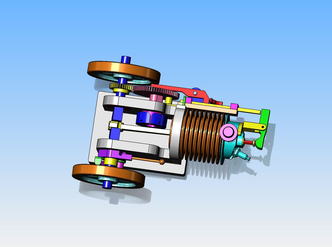
After doing a lot of research, I have found a governor which gives a much stronger reaction and takes up no space on the outside of the engine frame, allowing the flywheels to set in closer to the center of the engine. This governor is very similar to a flyball governor and sets inside the engine frame and just clears the connecting rod.


Brian,
Would there be enough clearance with the conrod, looks very close.
Cheers
Andrew
Would there be enough clearance with the conrod, looks very close.
Cheers
Andrew
Ghosty--if I did my math right, there should be 0.100" clearance.---Brian
This morning, after searching around a great deal, I found the engine which uses this type of governor. It is a Hercules engine from the early 1900's. Attached is a rather crummy video of the engine, and you don't see the actual governor until very near the end of the video at 6:11.
There are several that use similar, these from a Ruston Hornsby I started making one of these a few years ago but on the back burner at the moment. These like the one in your video link are geared from the larger cam gear so they run faster which should be easier to get working than scaling down a slower rotating one on a cam gear.
Attachments
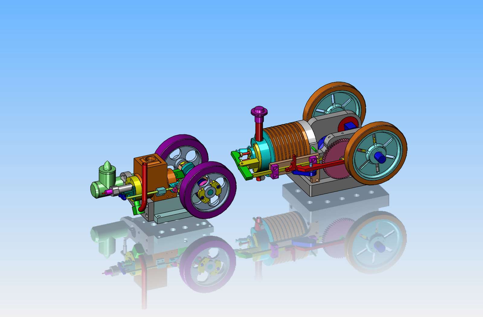
And just because I can---This is the Kerzel engine and my new engine together. Admittedly, the fact that my new engine is air cooled and the Kerzel is water cooled, makes quite a dramatic size difference in the cylinder diameters. Also, the Kerzel is 3/4" bore, while my new engine is 1" diameter bore. The Kerzel has 3 1/2" diameter flywheels, my new engine has 4 1/2" diameter flywheels.

Just can't sit still can you? LOL!
Steve--You're absolutely right. It drives me a bit crazy, and I've always been this way.---Brian
Similar threads
- Replies
- 35
- Views
- 3K
- Replies
- 1
- Views
- 699


![MeshMagic 3D Free 3D Modeling Software [Download]](https://m.media-amazon.com/images/I/B1U+p8ewjGS._SL500_.png)


