I've worked for a couple of large companies that had casting foundries. The dies were made of h7 steel, and each die section had a thermocouple in it. These thermocouples were always covered in a copper based heat transfer paste before being fitted into the die sections, to ensure that they get a true temperature reading from the die section they were inserted into. I have never made a cast iron liner with an aluminum outer cover, but I'm wondering if I should use a similar heat transfer paste, and where I could get it in Canada..
You are using an out of date browser. It may not display this or other websites correctly.
You should upgrade or use an alternative browser.
You should upgrade or use an alternative browser.
Time for a new Horizontal Hit and Miss engine
- Thread starter Brian Rupnow
- Start date

Help Support Home Model Engine Machinist Forum:
This site may earn a commission from merchant affiliate
links, including eBay, Amazon, and others.
Kind of confirms what I thought the engine won't breath that well. From your hot rod days you would have ported and polished things to keep a smooth flow. Even more important on a hit & miss engine as it will suck and blow cooling air through the held open exhaust when the engine is missing.
Easiest fix would be to counter bore the head so you can put a fine 3/8 or 5/16 thread in and then you can run 1/4" bore tube and open up the muffler a lot more.
This is my midget, 7mm around the valves, 6mm passages in head and 6.5mm ID exhaust so that's 31mm2 area around the valve stem and only a slight drop to 28mm2 passages that's 0.044sq inch on a slightly smaller engine bore.

This is the similar 24mm bore Thompson which has fine M8 thread for the same size exhaust pipe as the midget

Easiest fix would be to counter bore the head so you can put a fine 3/8 or 5/16 thread in and then you can run 1/4" bore tube and open up the muffler a lot more.
This is my midget, 7mm around the valves, 6mm passages in head and 6.5mm ID exhaust so that's 31mm2 area around the valve stem and only a slight drop to 28mm2 passages that's 0.044sq inch on a slightly smaller engine bore.

This is the similar 24mm bore Thompson which has fine M8 thread for the same size exhaust pipe as the midget

Last edited:
Yes Jason, you're right. I will see what I can do to open that exhaust passage.---Brian
Bad case of lazy-butt today, but some parts were made. Two push-rod guides and a handle for the adjustable ignition points bracket. I'm using up some of the material that I bought for $100 a few weeks ago. A ton of material, but just what material is "Best guess". Lots of mystery steel as well as brass, bronze, aluminum and copper.
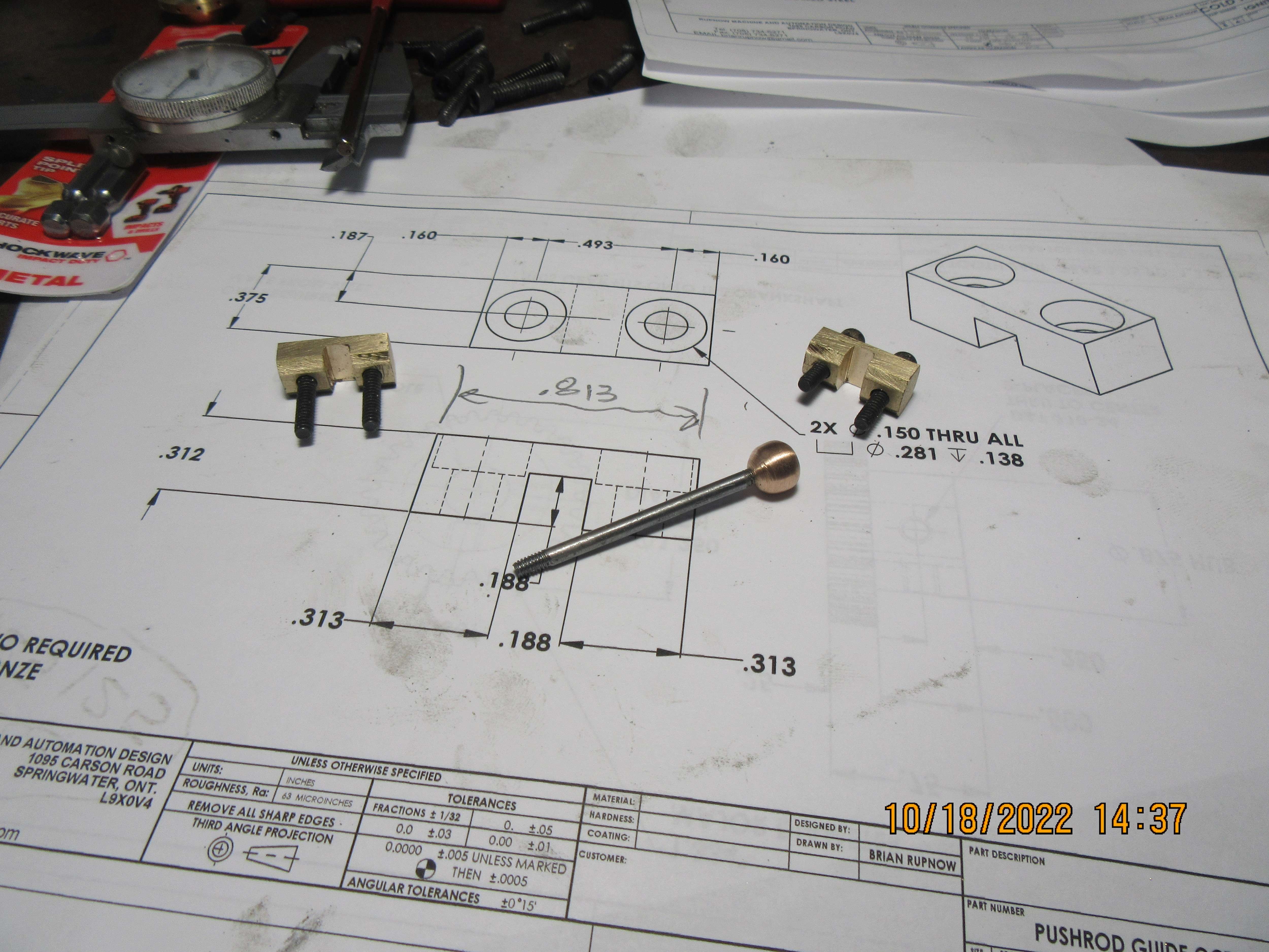

Brian,
You won't need heat transfer paste between the cylinder liner and cylinder outer, just a light press fit is all that is needed, The reason that it is used with the thermocouple setup is to get accurate and consistent readings, I use a copper paste when fitting temp sensors on my aircraft engines for the same reason.
Cheers
Andrew
Thank you Andrew.
![DreamPlan Home Design and Landscaping Software Free for Windows [PC Download]](https://m.media-amazon.com/images/I/51kvZH2dVLL._SL500_.jpg)
$0.00
DreamPlan Home Design and Landscaping Software Free for Windows [PC Download]
Amazon.com Services LLC

$599.00
$649.00
FoxAlien Masuter Pro CNC Router Machine, Upgraded 3-Axis Engraving All-Metal Milling Machine for Wood Acrylic MDF Nylon Carving Cutting
FoxAlien Official

$19.15
$29.95
Competition Engine Building: Advanced Engine Design and Assembly Techniques (Pro Series)
MBC Inc.

$99.99
AHS Outdoor Wood Boiler Yearly Maintenance Kit with Water Treatment - ProTech 300 & Test Kit
Alternative Heating & Supplies

$37.82
$49.99
Becker CAD 12 3D - professional CAD software for 2D + 3D design and modelling - for 3 PCs - 100% compatible with AutoCAD
momox Shop

$45.99
Sunnytech Mini Hot Air Stirling Engine Motor Model Educational Toy Kits Electricity HA001
stirlingtechonline

$26.89
$34.99
Peachtree Woodworking Supply Bowl Sander Tool Kit w/Dual Bearing Head & Hardwood Handle, 42 Pieces Wood Sander Set, 2 Hook & Loop Sanding Disc Sandpaper Assortment, 1/4 Mandrel Bowl Sander
Peachtree Woodworking Supply Inc

$49.95
$55.99
DjuiinoStar Hot Air Stirling Engine Assembly Kit: Spend 30 Minutes to Build Your Own Stirling Engine
djuiinostar
How about the thermal paste used on CPU?I've worked for a couple of large companies that had casting foundries. The dies were made of h7 steel, and each die section had a thermocouple in it. These thermocouples were always covered in a copper based heat transfer paste before being fitted into the die sections, to ensure that they get a true temperature reading from the die section they were inserted into. I have never made a cast iron liner with an aluminum outer cover, but I'm wondering if I should use a similar heat transfer paste, and where I could get it in Canada..
regards
Nikhil
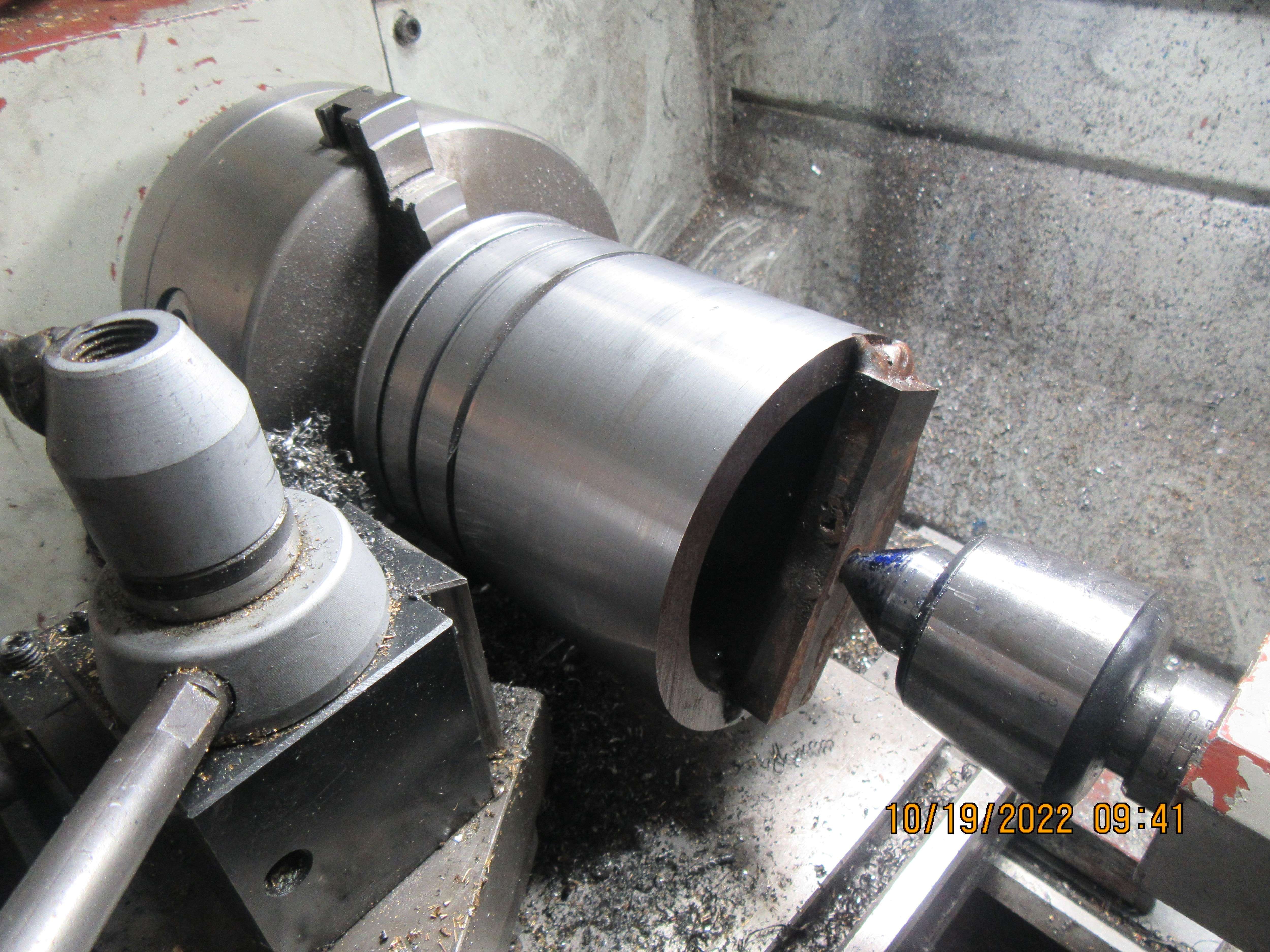
Yesterday evening I felt that I should do one more thing to round out the day, so I set up a piece of 4 1/2" o.d. heavy wall pipe in my lathe, turned the o.d. to 4.375", and then parted off two rings which will become flywheels. The walls on this pipe are .450" thick, so I made my cuts only 0.350" deep and will finish cutting them free from the pipe if my bandsaw blades ever get here. Nasty work indeed--lots of squealing, smoking (from the cutting oil) and lots of vibration. Jason--I took your advice and opened all the passages in my cylinder heads and exhaust to have a minimum of 0.25" (6.35mm).----Brian



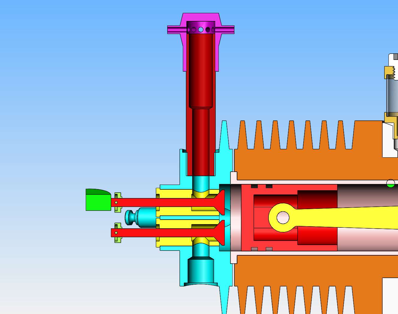
Jason--I have opened up my intake and exhaust ports and the inside of the exhaust pipe to 1/4" (6.35mm). I have opened the twelve holes around the spark arrestor to 0.075" diameter . Not sure what carburetor I will use yet.---Brian

That should do the trick
Don't go too big on the inlet as you want a reasonable velocity through the carb to get it sucking up the fuel and atomise it, 5mm or 3/16" would be about right for the tube you mount it to particularly with the Traxxas carb when you think how fast those engines rev compared to a slow hit and miss.
Don't go too big on the inlet as you want a reasonable velocity through the carb to get it sucking up the fuel and atomise it, 5mm or 3/16" would be about right for the tube you mount it to particularly with the Traxxas carb when you think how fast those engines rev compared to a slow hit and miss.
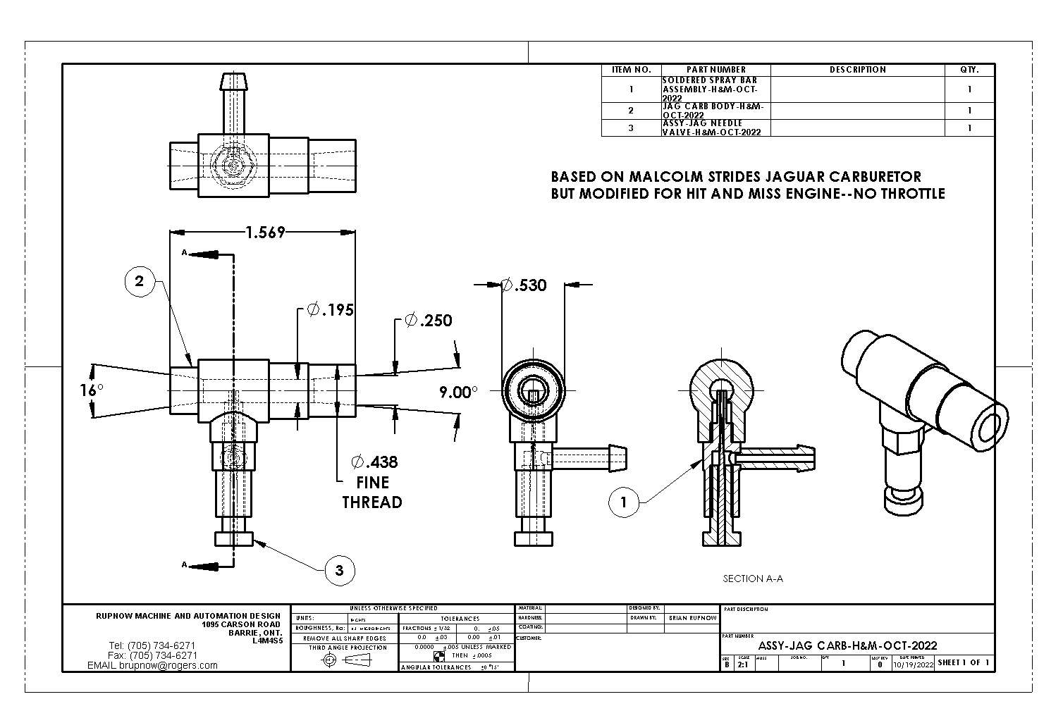
Jason--Just so I get this right--Are you telling me I should have a smaller throat size on the carburetor than the exhaust system? At this time, it is great to find out, as I can design the carburetor to whatever works best. I am thinking of using Malcolm Strides carburetor without a working throttle for this engine.---Brian
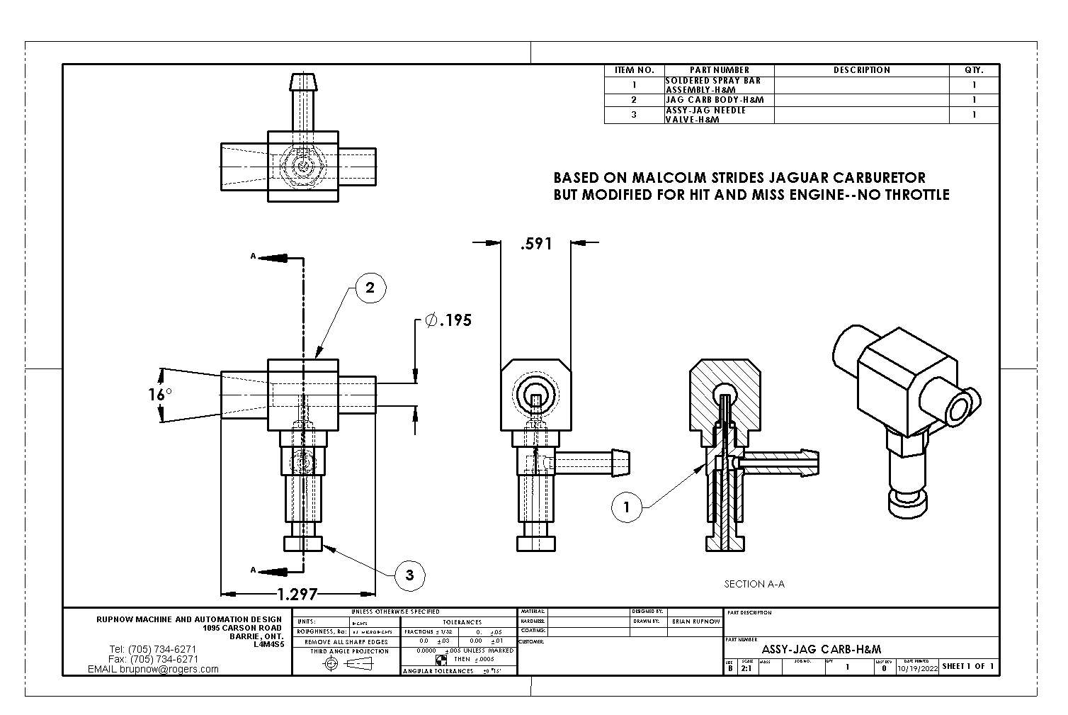

Last edited:
That looks about right to me, but I would suggest a taper draught tube on the outlet side of the carb, back up to your 1/4" port diameter. As I understand it, that is, If anything, more beneficial than a taper or bell-mouth at the inlet. The outlet taper wants to be no more than about 10° included.
Okay Charles--I have reworked the carburetor body somewhat, to make it fit where it has to go. I have put a 9 degree included angle taper in the discharge side of the carburetor, opening up to the 1/4" dimension.



Just turn the lathe chuck by hand.I have thin 'piano wire' thick springs to make. The slowest my lathe will turn is 70rpms. It gives me the willies just thimking about not being able to turn off the machine if somehow my fingers should get caught, wrapped up in the wire somehow.
.
On both the flat twin based on malcom's Bobcat and the midget shown above I went with tapered inlet and then straight through with 5mm much the same as your 0.195 like your first drawing I'm sure you have seen the videos of them running. Thompson is the same. Could probably have done the inlet in the head at 5mm too but did it 6mm


Jason - the thing to avoid, from a theoretical point of view at least, is a sudden increase in diameter. Because it is 'lossy' it decreases the velocity and vacuum achieved in the throat. A slow taper, the most efficient is about 6° included, allows Bernoulli to do his stuff. Counterintuitive though it may seem, a sudden contraction is less significant, and a short taper or bell-mouth entry is best.
A while ago, to check a new taper D-bit reamer was cutting OK, I cut a taper in a short offcut of 1/2" aluminium bar, going from 5/32" to 1/4". Out of interest I put a bell-mouth at the other end. When they try it, people are surprised, as I was, to discover how much easier it is to blow through it from the bell-mouth end than from the taper end.
A while ago, to check a new taper D-bit reamer was cutting OK, I cut a taper in a short offcut of 1/2" aluminium bar, going from 5/32" to 1/4". Out of interest I put a bell-mouth at the other end. When they try it, people are surprised, as I was, to discover how much easier it is to blow through it from the bell-mouth end than from the taper end.
Richard Hed
Well-Known Member
- Joined
- Nov 23, 2018
- Messages
- 2,801
- Reaction score
- 758
THAT seems very interesting. However, to make sure I understand, can you show a diagram?Jason - the thing to avoid, from a theoretical point of view at least, is a sudden increase in diameter. Because it is 'lossy' it decreases the velocity and vacuum achieved in the throat. A slow taper, the most efficient is about 6° included, allows Bernoulli to do his stuff. Counterintuitive though it may seem, a sudden contraction is less significant, and a short taper or bell-mouth entry is best.
A while ago, to check a new taper D-bit reamer was cutting OK, I cut a taper in a short offcut of 1/2" aluminium bar, going from 5/32" to 1/4". Out of interest I put a bell-mouth at the other end. When they try it, people are surprised, as I was, to discover how much easier it is to blow through it from the bell-mouth end than from the taper end.
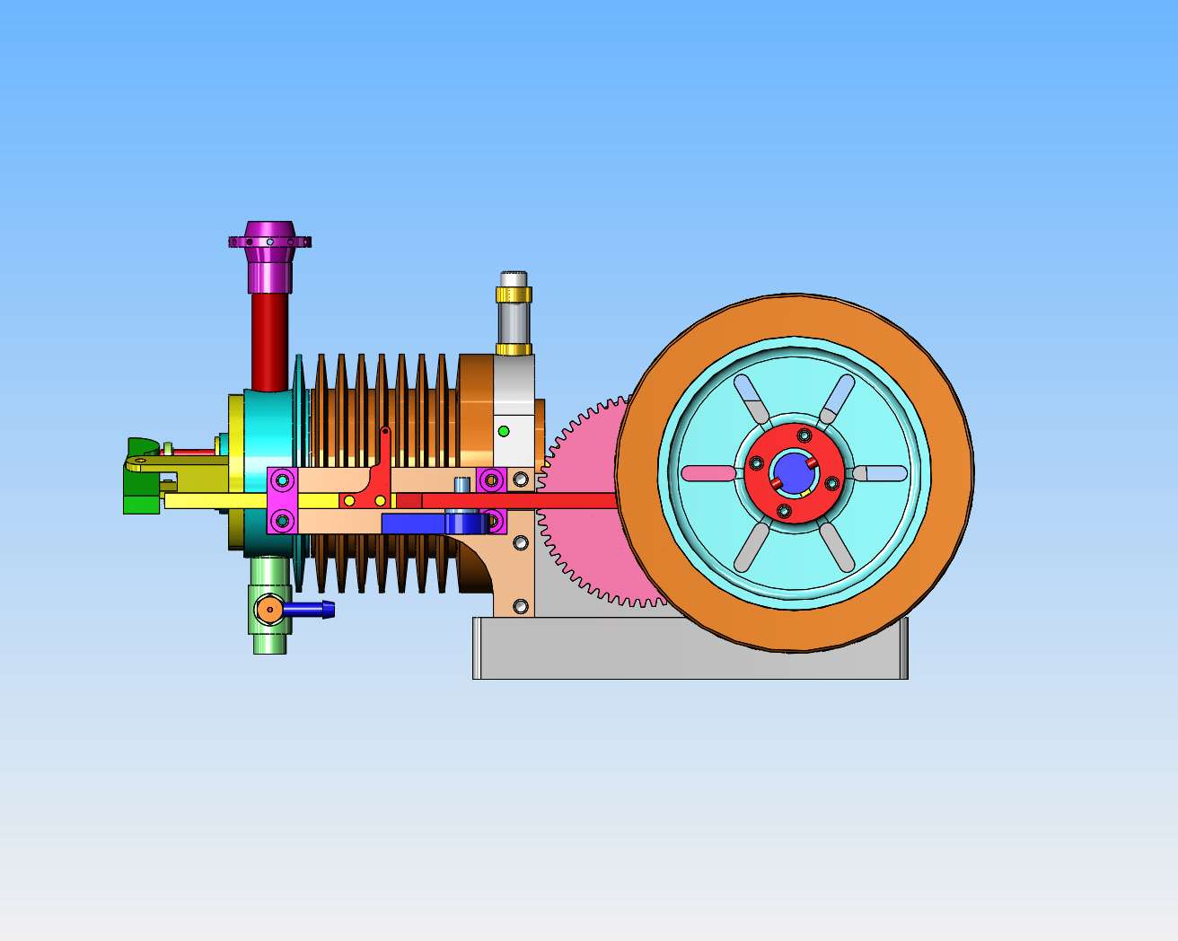
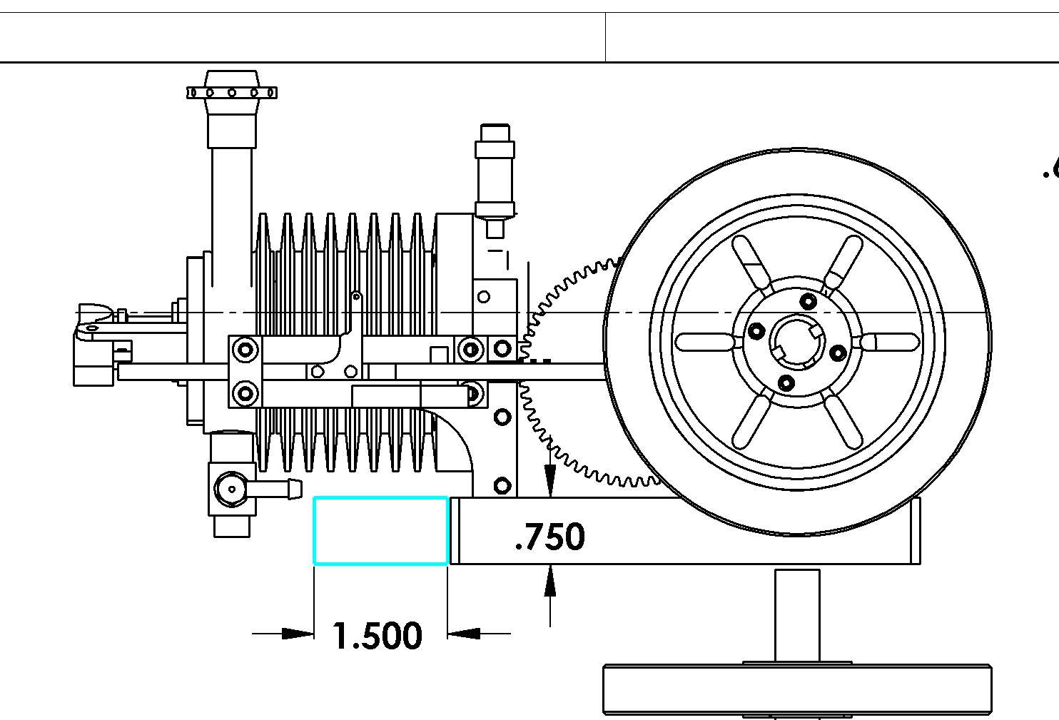
Today I have to go across town and buy the 1144 stress-proof steel to make the crankshaft, the cast iron for the cylinder liner, and the aluminum to make the cylinder head. In the meantime, I have to design a gas tank for this critter. The only real restriction is that the top of the gas tank has to be below the centerline of the carburetor. From what I've seen on the internet, the gas tanks were very shallow and tucked in underneath the cylinder, or they were very shallow and stuck out at the other end of the engine, or were mounted on the side of the engine. Mounted on the side of the engine works, but doesn't look good (I like symmetry). Directly below the cylinder is rather appealing, but a lot of heat comes of the air cooled cylinder so I'm a bit ginchy about putting a fuel tank there. I am going to design something right now, and I will post a picture when I finish.---Brian
I do like this. If I tuck a gas tank in here, I can use a piece of 1 1//2" sq. x 1/8" wall rectangular tubing for the gas tank body, with one side cut down to 3/4" high, which is below the carb centerline. The base is 3.9" long, the cylinder is only 2.9" diameter, so I could put a filler cap at one end of the tank. This is my favourite, because it doesn't change the "footprint" of the engine.

Similar threads
- Replies
- 34
- Views
- 3K
- Replies
- 1
- Views
- 688


![MeshMagic 3D Free 3D Modeling Software [Download]](https://m.media-amazon.com/images/I/B1U+p8ewjGS._SL500_.png)


