Thumper--a 1 3/8" bore i.c. engine

Home Model Engine Machinist Forum

Help Support Home Model Engine Machinist Forum:

This site may earn a commission from merchant affiliate links, including eBay, Amazon, and others.
Brian, I'd like a review on how you are making the gas tank. Looks to be a steel body, yes? Soldered on filler and outlet, I presume? But here's my main question: you mention putting the ends in using JB Weld. What are you using for the sight glass (glass, acrylic, or ??), and what type of JB Weld are you using? Sight glass at both ends, or a solid cap at one end?

I have to confess that, on my nearly-finalized Webster, the gas tank and its mount turned out to be the most time consuming and frustrating parts to make. That undoubtedly had something to do with my overly complicated design, plus my poor execution ...
 
Awake--Drilled and reamed 3/8"hole in center of tank. (tank is steel seamless tubing 1 .765" o.d. x 1.213" i.d.) Took a piece of 1/2" diameter cold rolled and turned one end down to 3/8" dia. x 5/16" long. Why?---Because it will hold the mount square and true to the tank body. Counterbored both ends of tank body to 1 1/2" diameter x 1/8" deep. Silver soldered the mounting rod in place. Held the mounting rod in 3 jaw lathe chuck and drilled a 3/4" hole in opposite side of tank from mounting rod, then bored the hole out to .825" diameter x approximately 3/16" deep from outside of pipe body. Took a 1/2" standard pipe nipple and turned one end of it to 3/4" diameter. Fitted it into 3/4" hole in tank and silver soldered it in place. Turned a couple of pieces of 1/4" aluminum plate to 1 1/2" diameter. Drilled and tapped one of these with a 1/8" npt thread. You can buy a fitting at the hardware store to screw into this hole. Loaded both recesses which were counterbored into the pipe ends with original J.B. Weld, set the round aluminum plates into the recesses and put the tank into my 4" mill vice to set up for 24 hours. You can buy a "J.B.Quickweld that sets up quicker, but I find that it doesn't hold as well as the original J.B. Weld. The pretty brass cap is turned from a 1/2" standard pipe cap. Now you can tell me, this is ridiculous---Why make a gas tank so strong that a Sherman Tank could run over it without damaging it.---Because it works!! Fooling around with thin wall tubing makes me crazy. Once the tank is all assembled, nobody knows that the tank has a wall .27" thick.
 
Awake--Drilled and reamed 3/8"hole in center of tank. (tank is steel seamless tubing 1 .765" o.d. x 1.213" i.d.) Took a piece of 1/2" diameter cold rolled and turned one end down to 3/8" dia. x 5/16" long. Why?---Because it will hold the mount square and true to the tank body. Counterbored both ends of tank body to 1 1/2" diameter x 1/8" deep. Silver soldered the mounting rod in place. Held the mounting rod in 3 jaw lathe chuck and drilled a 3/4" hole in opposite side of tank from mounting rod, then bored the hole out to .825" diameter x approximately 3/16" deep from outside of pipe body. Took a 1/2" standard pipe nipple and turned one end of it to 3/4" diameter. Fitted it into 3/4" hole in tank and silver soldered it in place. Turned a couple of pieces of 1/4" aluminum plate to 1 1/2" diameter. Drilled and tapped one of these with a 1/8" npt thread. You can buy a fitting at the hardware store to screw into this hole. Loaded both recesses which were counterbored into the pipe ends with original J.B. Weld, set the round aluminum plates into the recesses and put the tank into my 4" mill vice to set up for 24 hours. You can buy a "J.B.Quickweld that sets up quicker, but I find that it doesn't hold as well as the original J.B. Weld. The pretty brass cap is turned from a 1/2" standard pipe cap. Now you can tell me, this is ridiculous---Why make a gas tank so strong that a Sherman Tank could run over it without damaging it.---Because it works!! Fooling around with thin wall tubing makes me crazy. Once the tank is all assembled, nobody knows that the tank has a wall .27" thick.

Very helpful, thanks! So there is no sight glass, right? That is a major reason that my tank design was so involved - trying to include a sight glass, which required a flange with an o-ring and a screw-end end piece to trap it together. I still wound up with a tiny leak, so I tried to plug it with a JB Weld branded product - but it was not the epoxy; rather a high-temp gasket product. Which turned out NOT to be resistant to gasoline. :(
 
A sight glass is a great thing. I have one in the gas tank for my Atkinson engine. They add another level of complexity to something that you really don't want leaking.
 
Wait - it's not supposed to leak? Darn - back to the drawing board ...

:)

I had thought I was going to have to remake the tank a different way, and that would probably have been a good thing, giving me a chance to improve on some of the sloppy execution on the first go-round. But after I stripped out the JB Weld-branded non-fuel-resistant sealant, I used some actual fuel-resistant sealant instead (who knew that they made such a thing?!), and it seems to be working. So for the moment I'll live with the ugly execution - I'll try to improve on the next engine I make.
 
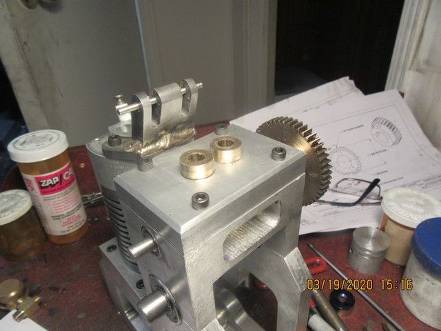
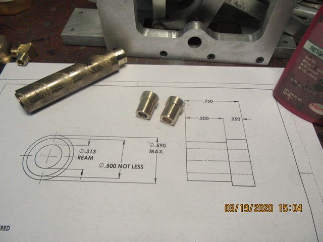
This afternoon seen two tappet guide bushings machined and pressed into place. I don't know exactly what grade that stick of bronze is, but it is miserable stuff to machine. All my turning was done with inserted carbide tooling. It seemed to be even harder to work with than 1018 cold rolled stock. The gas tank still requires a little work, but I will give the j.b. weld 24 hours to set up before I do any further machining on the tank.
hwvw1x.jpg

WVuoJu.jpg
 
This morning we have valves. I haven't parted off the large diameter yet, as I will use it for a handle when lapping the valves into the valve cages. Now I have an admission to make--Last week when I was machining the pivot pins for the main rocker, I ended up with about 3" of brass rod left. I said to myself "Ah-ha--I'll keep this bit of brass to make valve cages from. I have looked hi and lo all day yesterday for that piece of brass, and it has disappeared. I think the fairies have been to my shop. I do have a piece of 3/4" brass that I can use, but it just kills me turning so much uber expensive brass into chips!!!
k3vQe9.jpg
 
Oh, I hate it when that happens ... and it happens all too often! I'm still looking for one piece of material from months ago, except that now I've forgotten what it was. But I'm sure I'll recognize it when I finally do stumble across it! :)
 
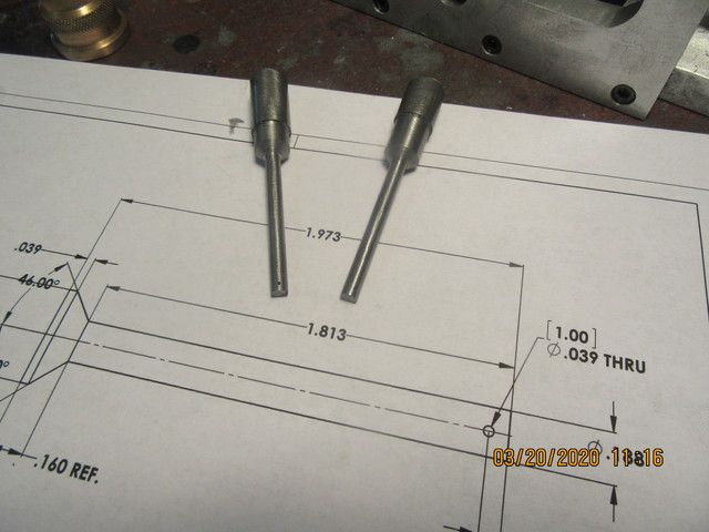
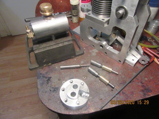
The gas tank is finished and the valve cages have been made. I have to make a new valve seat cutting tool because I want to put the chamfer into the valve cages before I press and Loctite them into the cylinder head. The hole thru the side of the cages will be drilled thru the cylinder head and the cages after they have been assembled together.
J7o7WR.jpg
 
(I ended up with about 3" of brass rod left. I said to myself "Ah-ha--I'll keep this bit of brass to make valve cages from.)
It's OK Brian, you will find it tomorrow;)
 
Hey Brian:
You might want to look this guy up. He's a Youtuber in / around Barrie as well and is looking for some help operating his new machines from Craftex from Busy Bee. He runs a small engine repair shop. He might be a good source of info and perhaps small parts for your engine builds.
 
dsage--Normally I would jump on this and try to find the guy to help him. However, with this current virus scare, wife and I are locked down and self isolating. Wife has high blood pressure and I am an old guy, so we are trying really hard not to get exposed to any potential virus threats.---Brian
 
Yes. I thought of that after posting. But maybe for future reference then. If you get his contact info you could call him if you need something. He seems a pretty friendly and knowledgeable guy.
 
I'm getting right down to the short strokes on this engine. Have to machine a crankshaft and a couple of cams (which are the same). It's been so long since I machined a cam that I will have to study notes I made on cutting a cam using the Chuck Fellows method. Right now I'm undecided about the crankshaft, whether to machine from solid or make a "built up" crank. Looking at the engine, I see that I also need rocker arms and tappets, and the two 90 degree elbows that screw into the cylinder head. I would like to make the elbows from brass, but I don't have any brass stock to make them from. The flywheels are going to be something "special", and right at the moment I don't have any stock to make them from. It's plain that after my two weeks of "social distancing" I'm going to have to risk it and go see my metal supplier.
 
Brian:
Your stick of bronze appears (to me) to be 660 "bearing bronze". I say that because it looks to have that spiral greyish mark the length of it on the outside. Not sure why it has that and my only reason for saying that is that I've been getting it for years like that from Metal Supermarket. BUT recently I went to get some more and they seem to have stopped stocking Bronze all together at my go-to outlet. They had a small piece about 10" long left on their cutoff shelf but it was labelled Aluminum Bronze. From my experience I think it was mis-labelled. They often mislabel short ends of stuff at that store.
In any case 660 is ideal for bushings and is quite "crunchy" and small chips jump off it when machined with a sharp tool.
 
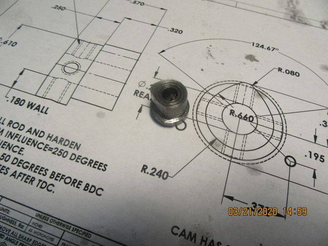
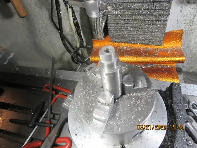
A few years ago when I built the Rockerblock engine, I did some serious studying on how to cut a cam in my milling machine. This is not the incremental version as used by Malcolm Stride, but a totally different method based on a how to video posted by chuck Fellows. It does incorporate all of the math from the cam drawing, but uses a combination of rotary table and full depth plunge cuts with the milling machine. It is very fast and simple if you can get your head around how the set-up works. This morning I opened an old thread I had created about using this method of cutting a cam, and read a bunch of notes I made about it at the time. I set up everything according to the notes I had made and began to cut. About half way thru, my set-up slipped and I lost my reference point. I decided to continue to the end and see what conclusions I could draw from the way I had my set up. The cam was truly screwed up, but there is enough to show that if my set-up hadn't slipped, it would have given a properly shaped cam with radiused cam flanks.
OV5HR1.jpg
 
There are opportunities to learn every where.
 
There are opportunities to learn every where.

You know that saying, "you learn something new every day?" I always add, "if you're lucky."

Relevant part: Brian, back to piston rings a sec. You said you tried Dave Reed and never got an answer by email. I was concerned he was gone as a source, but I emailed him about getting replacements for my Webster rings that I broke and he answered right away. They're on order.
 

Latest posts

Back
Top