Throttle governed engine

Home Model Engine Machinist Forum

Help Support Home Model Engine Machinist Forum:

This site may earn a commission from merchant affiliate links, including eBay, Amazon, and others.
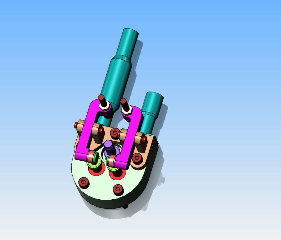
Okay--I spent the morning on a redesign of the cylinder heads. IF I decide to go ahead and do this, it would move the sparkplug up to a point above the centerline of the cylinder. It would mean new heads, and everything in them. That is a lot of work.--Then again, I don't have a lot of other stuff going on. The only thing that makes this a somewhat attractive notion, is that I have all the material here to do it without having to buy anything. I will think on this for a while---
gqKGd8.jpg
 
Reading back through the last couple of pages and just wondered what overlap you have on the cams.
Fuel misting back out through the carburettor is normal on some engines at low revs but usually clears as the revs get to a more normal level.
That said, increased overlap can create problems in this area as well as the duration you previously mentioned.
However they would need to be rather "wild" grind to get this effect from duration.
Common is around 110 degrees.
Also with reference to your ignition, for one, the polarity of coil to battery is an important factor.
Aside from that, not having a blue spark with points and kettering system is an indication of a crook condenser.
Other factors aside, once then engine is running, it doesn't really matter where the plug is located.
There are radials which cope quite well to having plugs at the bottom.
 
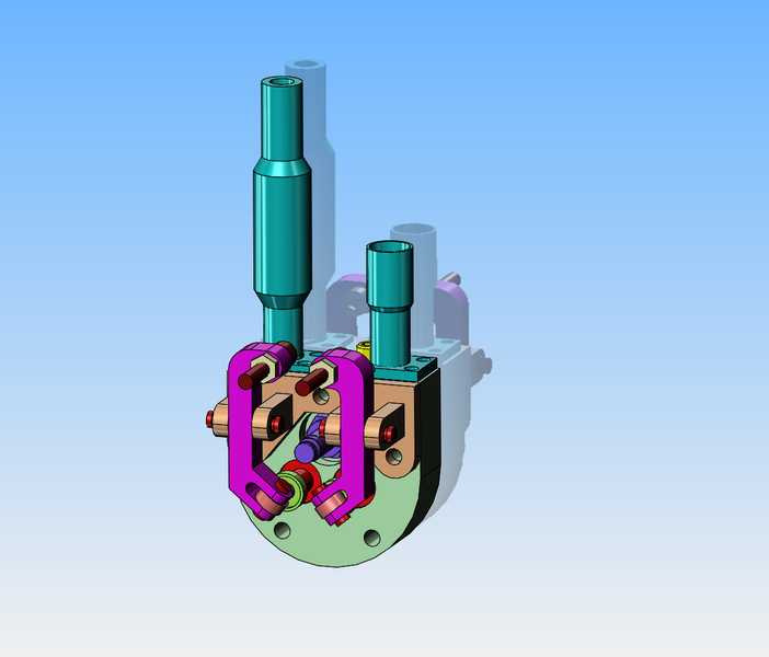
After posting the previous 3D model, I went up to the mall for my "fat mans walk". As I walked along (four times around the mall is 1.6 miles) I was running thru this design in my head, and realized that the axis of the rollers that contact the top of the valve should be parallel to the rocker arm pivot pins. so--A slight change to the shape of the rocker arms corrects that issue, and actually makes for a simpler rocker arm.
dpHLoF.jpg
 
Here's another thing to consider Brian is that a lean mixture is harder to ignite than say stroich so a stronger spark or less plug gap is needed. Oh by the way my 4 stroke ASP 0.65 RC engine uses exhaust pressure to the tank so it's just not for 2 strokes. From what you have said I would look more towards the spark issue.

Ray
 
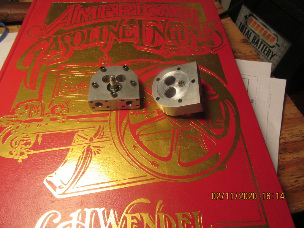
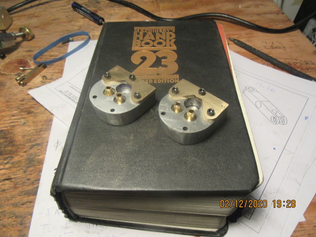
Here we have two new cylinder heads, which almost entail a full days work. Notice that the sparkplugs have been moved a lot closer to the side of the head which the manifolds bolt to, which places them high above the bottom of the cylinder bore. I still have to make valves, valve guides, rocker arms and brackets but I'm happy with these. I never noticed how dirty the business end of that sparkplug was until after I had taken the picture.
o5T2fH.jpg
 
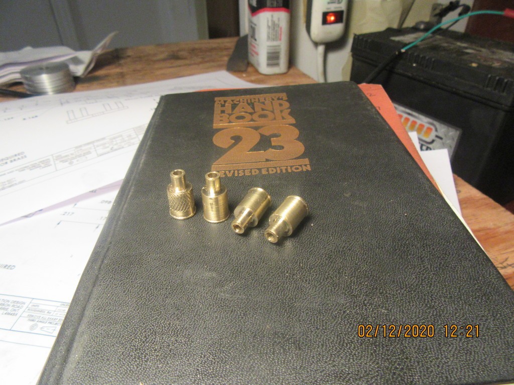
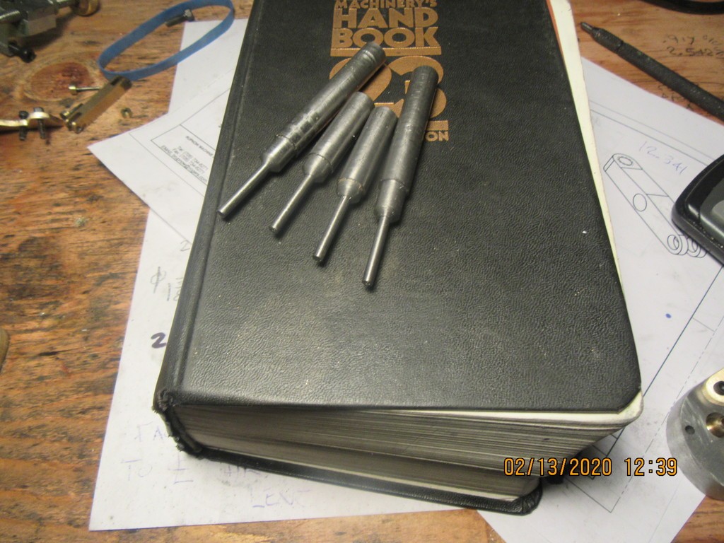
This mornings offering to the machine Gods is four brass valve cages. These cages get Loctited and very lightly pressed into the cylinder heads. The 0.125" thru hole and the 0.25" hole are both put in in the same set-up to guarantee concentricity. The one on the left was about .002" undersize so I knurled it lightly, which increases the diameter by about 0.010", then turned it down to the correct dimension. After the Loctite sets up (preferably overnight) I will use my George Britnel inspired valve seat cutting tool to put the 45 degree chamfer in the area where the valves seat.
TWNPpL.jpg
 
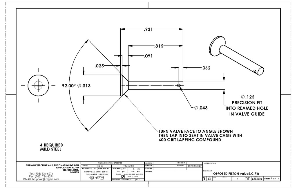
Brian, what is the diameter of the bottom of the valve - .313? Also, I've noticed in some of your write ups that you machine the valve 1° more acute than the valve seat - this seems like a brilliant idea to me. I presume it lets you bed the valve in more easily?
 
Hmm, that diagram makes me realize I had it backwards - I was thinking the total included angle of the valve was less than that of the cage, rather than more. Have you tried it that way (smaller angle/more acute)? Or maybe there is a good reason not to - the slight gap might allow a bit of burning of the exposed valve seat??
 
You want the contact line at the top of the valve, not the bottom. I don't even know what would happen if you had the contact line at the bottom. Many people make the valve and seat angle the same, and there is nothing wrong with that. I just have more success doing it the way I have on the previous 18 engines.
 
I spent the afternoon making the main bases of the rocker arm support brackets. Tomorrow I will have to build a welding jig to hold all of the vertical legs of the brackets in the correct place before silver soldering the brackets together.
RHZ23u.jpg
 
I think you are correct and it also is a place for carbon and junk to collect and possibly hold the valve open. I remember some of the early full size V8s used a slight difference between valve angle and seat.

Cheers
Willy
 
Thanks, Willy, that makes sense.

Brian, I apologize for side-tracking your thread. As always, you do splendid work, and what is particularly valuable to a newbie like me is the way that you walk us through your design choices. It is obvious that you've had a wee bit of experience in that area ... :)
 
Brian:
The quickest way to more power is more compression. Maybe it's a bit late now since you are installing valve cages but while you're making new heads take a few thou off the face of the head. You can always put a thicker head gasket in to put it back. More compression will also make some more heat and keep your plug cleaner. (of course with the requirement for a better spark).
Also, others have asked what your "real" valve timing is. I posted back in #63 on how you can measure your actual valve timing. It's a worthwhile exercise and it can also check you valve sealing and piston rings.
 
Last edited:
Back
Top