Throttle governed engine

Home Model Engine Machinist Forum

Help Support Home Model Engine Machinist Forum:

This site may earn a commission from merchant affiliate links, including eBay, Amazon, and others.
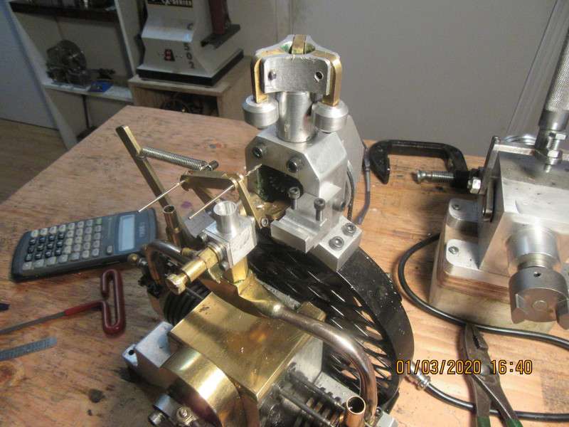
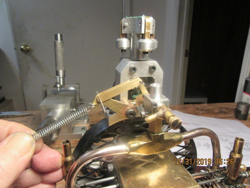
This morning I made the adapter which goes between the intake manifold and the carburetor, and the link which ties the governor lever to the carburetor throttle lever. I am not really sure what I'm doing here, and the more I do, the less sure I am. (That is not as unusual as it sounds!!). In the attached picture, my hand is holding the spring in tension, and the levers are pulled into what is actually a "wide open throttle" situation. As the engine runs and centrifugal force makes the governor weights swing out away from the center, it actually pulls the throttle lever against the spring tension, until the carburetor is in an "idle" position. I have to adjust the spring tension to a point where the engine will settle in and run at 2000 rpm. but not so far that the engine idles. Now, if a load makes the engine slow down, the governor weights won't have as much centrifugal force, and the spring tension will pull the lever into a more "open throttle" position, causing the engine to run faster and bring the speed back up to the magic 2000 rpm. So--The magic here seems to be my ability to adjust that spring tension so the engine runs at 2000 rpm but not any slower. However, that is only part of the equation. I also have to have the capability to completely over-ride the governor weights and bring the carburetor into a "full idle" position for starting. I THINK perhaps I need a counter spring pulling in the opposite direction to the spring I am holding, so that when it is engaged the carb throttle moves into a "full idle" position.
ZTz0Zj.jpg
 
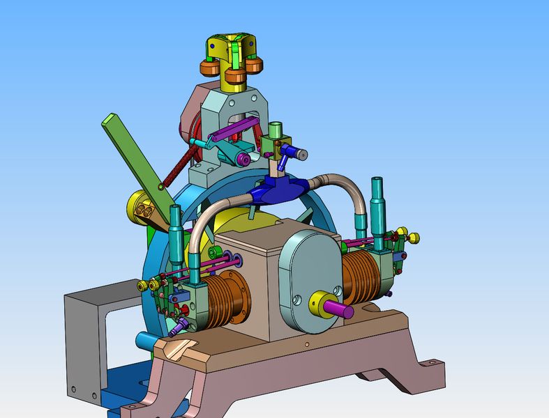
Update time---I really didn't want to cut the exhaust stack off on the governor side of the engine. Sometimes as I design and build these things, I see a way to change the design a bit and save myself some headaches. By brazing a piece of round 3/16" brass rod to the far side of the governor arm, I can move the spring over closer to the fan shroud to clear my exhaust stack. I have removed the pull cable and extra spring that showed up in a previous 3D model and went to a simple lever which I can move back and forth to determine the tension of the red spring. When I reach a point where the spring tension is strong enough to limit the motor rpm's to where I want them to be (about 2000 rpm governed) then I tighten the yellow threaded handwheel on the far side of the hand lever to lock it in place. I do have an idea for the mechanism that will completely overcome the governor and move the throttle into a closed position to make easier starting, but I have to chew on it for a while before I model it.
b1pA6w.jpg
 
When I reach a point where the spring tension is strong enough to limit the motor rpm's to where I want them to be (about 2000 rpm governed) then I tighten the yellow threaded handwheel on the far side of the hand lever to lock it in place. I do have an idea for the mechanism that will completely overcome the governor and move the throttle into a closed position to make easier starting, but I have to chew on it for a while before I model it.

For what it's worth, when I saw your post last night talking about this I started thinking of something with set screws to preposition where the lever is and keep it from going too far. I was trying to visualize it when the holiday interrupted and then I promptly forgot.

Now I'm thinking something like the old automatic chokes we had on our cars. A bimetallic strip to hold the throttle in a position that changes as the engine heats up.

I think they worked backwards from what you want; they started wider open and then slowed down. Aside from where to get the bimetallic strip (old heater/air conditioner thermostats used those, too), it doesn't seem that bad.

Reminds me of the sayin, "nothing is too hard for the man that doesn't have to do it."
 
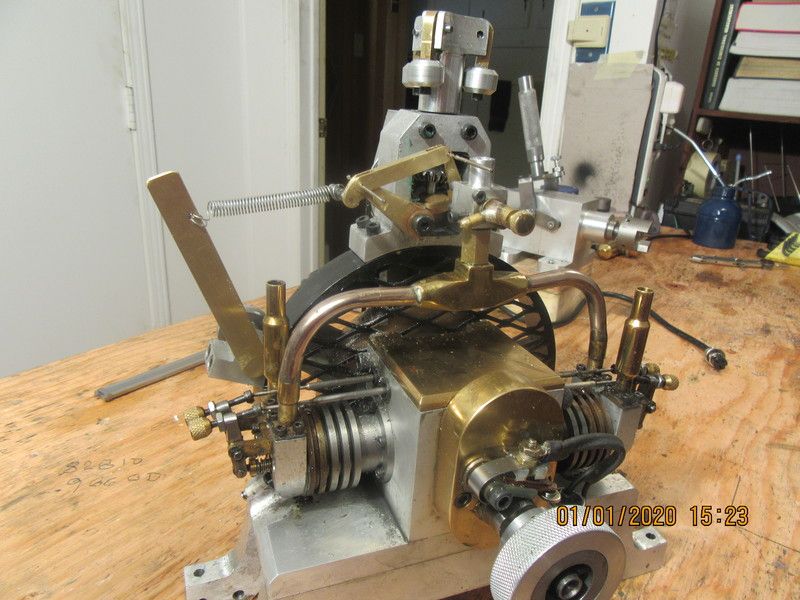
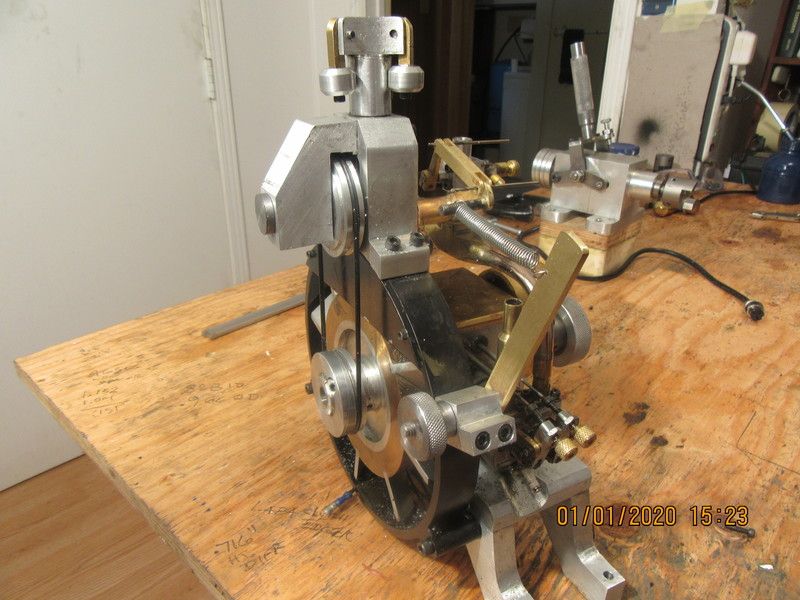
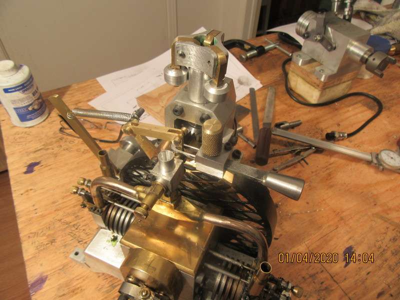
Today seen significant progress on the governor control lever. I can loosen off the knurled handwheel and swing the brass lever into whichever position gives the best spring tension. The spring tension is what sets the "governed speed". I was able to position everything so that I didn't have to butcher my exhaust stack. I still have to work on a mechanism to over-ride the governor and set the engine throttle into it's "idle" position, as that is the best position when starting the engine.
SacNw2.jpg

kbyU7R.jpg
 
Hi Trevor--I did a build thread on this engine a few years ago, and I do sell a complete 70 drawing set of plans for $25 Canadian funds. It is not based on a VW. I just wanted to arrange the fan blades so they blow a continuous stream of air across the cylinders. It will run all day without overheating.---Brian
https://www.homemodelenginemachinist.com/threads/opposed-twin-i-c.24899/
 
My plans are sold as pdf files.---That way you don't need any special software to open and view them. I have sold plan sets quite literally "All over the world", many in Australia and New Zealand.---Brian
 
Now we are in the final phase of this throttle governed engine. As it sets, two things are happening. With the engine setting at rest, not running, the single spring pulls the throttle on the carburetor wide open. When the engine is running and the governor weights fly outward, that puts tension on the spring and pulls the throttle into a closed position, but not all the way closed. I adjust the tension on the single spring to a point where the engine is running at 2000 rpm., which is close to the idle position, but not too close. This is a state of equilibrium between centrifugal force from the weights and the tension of the spring. Now there is only one issue left. These small engines are difficult to start when the throttle is "wide open". Now I have to devise an "over-ride" that will pull the throttle to the fully closed (idle) position for starting, but not effect anything else in the governor train. Once the engine starts and warms up in the "idle" position, I disengage this "over-ride" and the governor takes over to control the speed of the engine.--3D cad to follow---
 
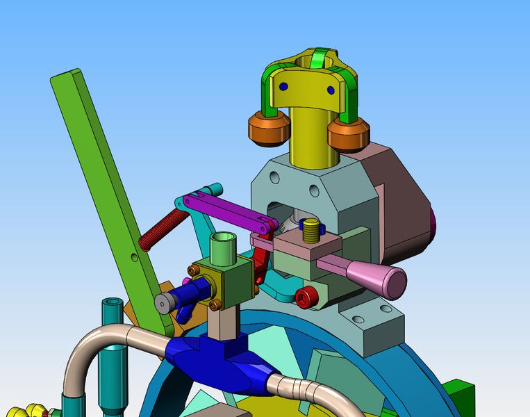
This is the mechanism which over-rides the throttle spring and moves the throttle lever into "idle" position for start up. The pinkish colored bar has a slot in it that fits around the throttle lever. It is all clearance except for the left end of the slot. This bar moves left or right, and is held in position by a ball detent screw (yellow). It rides in a guide which is bolted to the main governor tower. So--In the current model, the engine is stopped, the balls are in against the stem post, and the pinkish bar has been pulled to the extreme right and is held there by the ball detent screw. The left hand end of the slot is touching the throttle lever to pull it to the extreme right which is the idle position. The engine is started in this position, and allowed to warm up. Once the engine is warmed up, the pinkish bar is moved to the left, and no longer touches the throttle lever. At this point the governor takes over control of the throttle. The pinkish colored bar no longer touches the throttle anywhere.
8PoWxi.jpg
 
I will be "truly Impressed" if this system comes together like I'm imagining. I know that every sub assembly that I design works. I have built them before, and they worked. The big trick will be getting them all to work in harmony with each other. I know that similar full size machine assemblies work exactly as I want the model to. Best similar thing I remember was a local sawmill ran by a Caterpillar six cylinder diesel. It ran at a fast idle when the mill wasn't operating. As soon as the power was coupled to the stationary mill machinery, the engine would immediately kick up the throttle. It didn't run any faster, but the exhaust sound changed quite dramatically---You knew by the sound that it was working. Then when they put a 20" white pine log on the carriage and ran it through the saw, the engine would really start to blatt. It wasn't running any faster, but you knew by the sound that it was putting out tremendous power to keep the rpm's from dropping. After the log went through the main-saw, you could again hear the difference in the noise of the engine as it throttled back. It was all done mechanically, no human involved on the throttle controls. If I can do that on the scale I am working at, then yes, it's going to impress my socks off.---Brian.
 
Last night we had 4 year old grandson for a "sleep-over". He's a great little kid, but it didn't leave grandpa with a lot of machining time. I did manage to get the main idle bracket machined and installed. It is a rather complex shape, but turned out very well. I only have about one day of making parts left, and then I will see if all of these add-ons actually work. You would think that with all of the O-rings that I bought for the edger and then didn't use, I should have one that fits this application.---I don't. Everything I have is either too short or too long. Monday I will get on the phone and order one which fits this beastie.
eEWUec.jpg
 
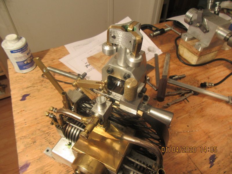
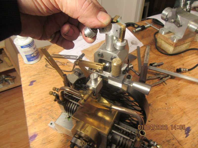
Okay boys and girls--we have a lot going on here. In the first picture, engine is stopped, governor over-ride pull knob is pulled to extreme right, which overcomes the tension spring and pulls the carburetor throttle lever into closed/idle position so the engine can be started. I didn't have a ball detent screw, so I made up a knurled and threaded brass knob which sets where the detent screw would have gone. I pull the governor over-ride to the extreme right and tighten the knurled brass knob so it stays there while I am starting the engine. Second picture shows the over-ride pull knob released, and the tension spring pulls the throttle to the wide open position. This is a situation that should normally never occur, because as soon as the engine starts, the governor balls will "fly outward" and pull against the tension spring, moving the carburetor throttle lever into a position which is actually quite close to the "idle" position. (if the engine were running, I would set the spring tension so the governor weights and the tension spring reach equilibrium at about 2000 rpm.) The third picture shows my hand holding one of the governor weights in it's "fly out" position, and you can see that the governor pulls the throttle lever back close to the idle position. That governor over-ride bar has an over-size clearance slot in it, and only contacts the carb throttle lever when it is pulled into the "engine start" position.
4SPxkp.jpg

p4rGSZ.jpg

LVRXCD.jpg
 
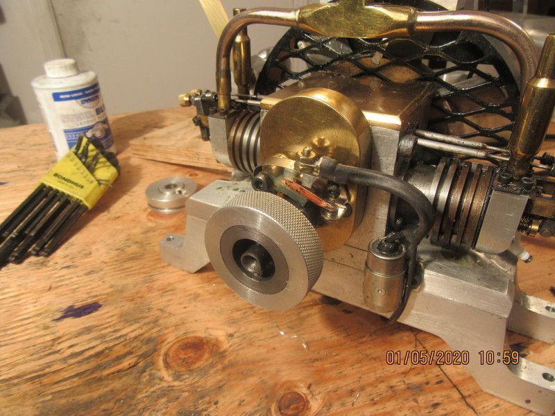
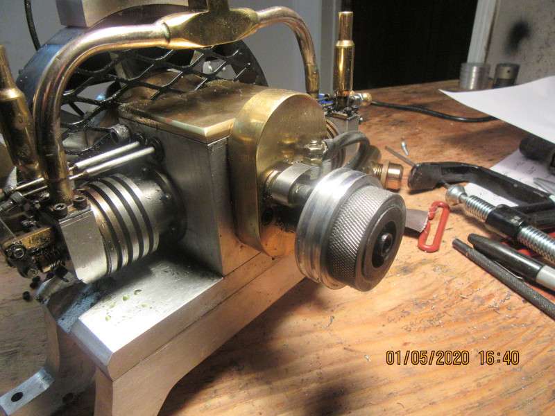
When I first built this engine a few years ago, I machined a steel starter hub which attached to the end of the crankshaft to engage with my electric drill for starting. Then I discovered that the compression was so high that I couldn't comfortably grip the starter hub in my hand to turn the engine thru it's different stages to set timing, etcetera. No problem--I just machined a larger diameter piece from aluminum, knurled the o.d., and Loctited it to the outside of the starter hub. The other end of the crankshaft isn't available for a power take-off pulley, so now I am going to rework the started hub so that it will keep the knurled profile for a hand grip, but also become a power take off pulley.---Brian
hB7Sni.jpg
 
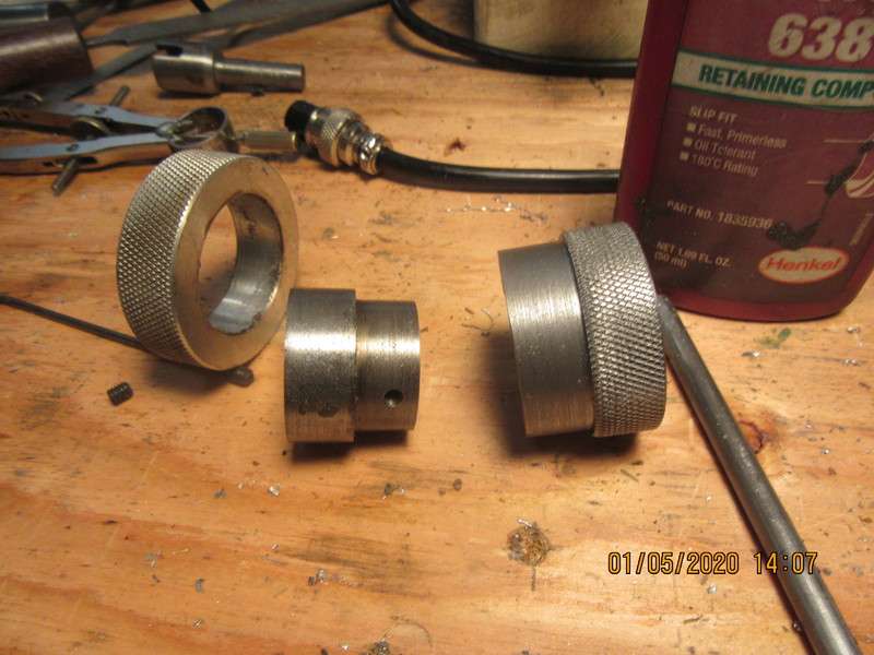
In this picture, the starter hub and knurled aluminum ring have been removed from the engine and separated. They were only loctited together. A new intermediate hub has been turned and knurled, and will replace the old knurled aluminum ring but will still incorporate the inner hub.
zmZI6i.jpg
 
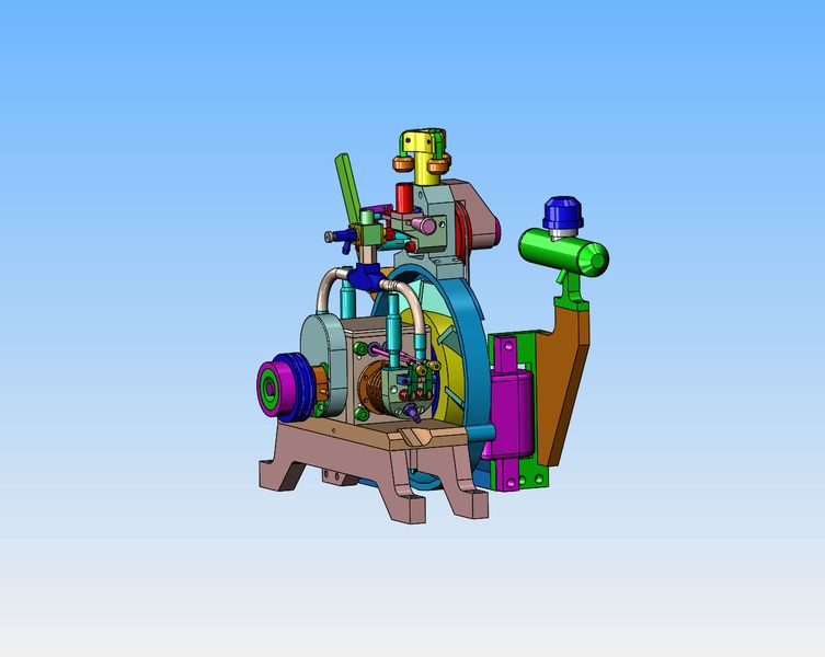
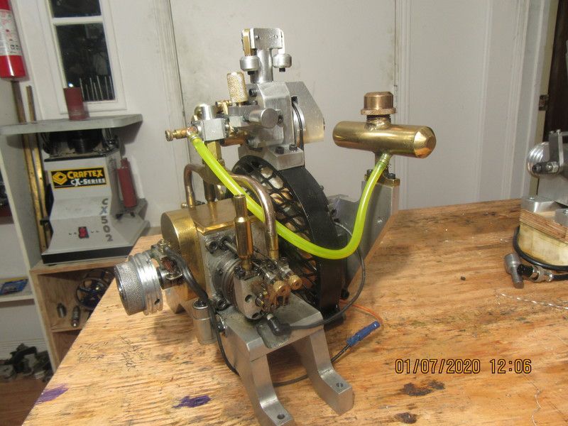
Any time you take an existing engine and "repurpose" it to a different style, as I am doing here, some things get a little weird. This engine was designed and built with a manually controlled throttle, and now is being changed over to a governor controlled throttle. All of the new parts are made and installed, but I still need to mount the gas tank somewhere. It has to be marginally lower than the center of the carburetor, it must be away from the exhaust pipes, and the gas tank outlet still has to exit in the general direction of the carburetor. Playing around with the 3d cad model, I have found a position that meets all of these requirements and only requires that I make up one new plate and mount it to the steel bracket that holds the ignition coil. Looks a bit weird, but it works. This uses the original gas tank with no changes to it at all.
gxNLmJ.jpg
 
This mornings work involved a new bracket to mount the gas tank, and a new, rather squirrelly looking yellow gas line. Gas tank and line clear all moving parts, avoid being close to exhaust stacks , and tank is marginally below centerline of carburetor. And that's it!!! I ordered a couple of new O-rings to drive the governor from the rear of the flywheel, and once they arrive we will see if this thing can fly---
gb1fYj.jpg
 
Back
Top