
You are using an out of date browser. It may not display this or other websites correctly.
You should upgrade or use an alternative browser.
You should upgrade or use an alternative browser.
This winter's project. A transmission for the 302 engine
- Thread starter gbritnell
- Start date


Help Support Home Model Engine Machinist Forum:
This site may earn a commission from merchant affiliate
links, including eBay, Amazon, and others.
- Joined
- Jul 16, 2007
- Messages
- 3,036
- Reaction score
- 1,124
It's been several days but here's where I'm at.
I had to figure the best way to remove most of the metal and still have some clamping area so with the larger cuts on the bottom I clamped from the centerline up. The first 3 pictures show the shifter box area. I cut the cavity and just enough around it to give me a witness. That left all of the other flat area for alignment.


I had to figure the best way to remove most of the metal and still have some clamping area so with the larger cuts on the bottom I clamped from the centerline up. The first 3 pictures show the shifter box area. I cut the cavity and just enough around it to give me a witness. That left all of the other flat area for alignment.
- Joined
- Jul 16, 2007
- Messages
- 3,036
- Reaction score
- 1,124
The next picture is some rough layout work and then off to the bandsaw to get rid of the big pieces.The first detail on the bottom was a boss up against the flange. I roughed around it and then went in with a .125 end mill with a small radius on the corner.


$99.99
AHS Outdoor Wood Boiler Yearly Maintenance Kit with Water Treatment - ProTech 300 & Test Kit
Alternative Heating & Supplies
![DreamPlan Home Design and Landscaping Software Free for Windows [PC Download]](https://m.media-amazon.com/images/I/51kvZH2dVLL._SL500_.jpg)
$0.00
DreamPlan Home Design and Landscaping Software Free for Windows [PC Download]
Amazon.com Services LLC


$426.53
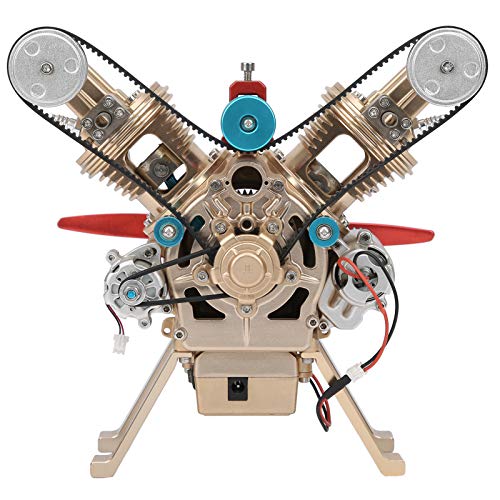
DM14 Engine Build Kit, Metal Engine Build Model Great Metal Material for Engineer for Factory
Easoger Official


$94.99
$109.99
AHS Woodmaster 4400 Maintenance Kit for Outdoor Wood Boiler Treatment
Alternative Heating & Supplies


![MeshMagic 3D Free 3D Modeling Software [Download]](https://m.media-amazon.com/images/I/B1U+p8ewjGS._SL500_.png)

$59.99
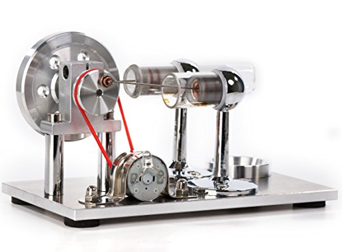
Sunnytech Hot Air Stirling Engine Motor Model Educational Toy Electricity Generator Colorful LED (SC001)
stirlingtechonline


$109.99
AmTech300 - Boiler Treatment Professional Strength (Rust Inhibitor For Outdoor Wood Boilers)
Alternative Heating & Supplies


$649.00
$699.00
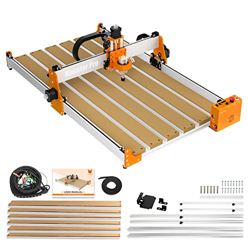
FoxAlien Masuter Pro CNC Router Machine, Upgraded 3-Axis Engraving All-Metal Milling Machine for Wood Acrylic MDF Nylon Carving Cutting
FoxAlien Official


$160.35 ($1.43 / oz)
Replacement Combustion Chamber Kit, Burnham V8 and V8H, 1-6 Sec, 108136-01, 1129
Plumbing Planet


$188.98
TM NEXDYNAMI RE41157 Water Pump Compatible With/Replacement For/John Deere 6200 7400 6300 6600 6500 6400 7220 7600 7200 RE41157
VIVID MARKET CORPORATION


$39.99
$49.99
Sunnytech Low Temperature Stirling Engine Motor Steam Heat Education Model Toy Kit For mechanical skills (LT001)
stirlingtechonline


$40.02
$49.99
Becker CAD 12 3D - professional CAD software for 2D + 3D design and modelling - for 3 PCs - 100% compatible with AutoCAD
momox Shop


$443.98
TM NEXDYNAMI AT29618 Water Pump Compatible With/Replacement For John Deere 1020 1520 2020 300 301 400 401 440 440A 480 AT29618
VIVID MARKET CORPORATION


- Joined
- Jul 16, 2007
- Messages
- 3,036
- Reaction score
- 1,124
Next came a setup for cutting the angled surface on the bottom. I roughly set it with a protractor and then went in with my dial indicator and checked the tangent of the angle. Then some more stock removal and stepping around the newly formed boss.


- Joined
- Jul 16, 2007
- Messages
- 3,036
- Reaction score
- 1,124
There are 2 ribs on the bottom of the tailshaft housing, a wider one near the back and then a thinner one about halfway up. (.150 and .063 respectively) The first 3 photos show the wide rib cut and the last one show the smaller on finished. It required several moves in the vise to set up for the angles and then finally some step-off work to get the blend angle between the 2 ribs.
George


George
- Joined
- Dec 28, 2008
- Messages
- 1,731
- Reaction score
- 9
gbritnell said:Next came a setup for cutting the angled surface on the bottom. I roughly set it with a protractor and then went in with my dial indicator and checked the tangent of the angle. Then some more stock removal and stepping around the newly formed boss.
Great post George! And thanks, you just taught a new trick using a bevel protractor.
Now I know how to use mine to set-up a work piece in my mill vise. This has been a problem for me in the past.
They way you used it with help from a 123 block never crossed my mind.
-MB
ya know George....you have had me stumped for some time.
You are impossible to categorize.....
Just when I think your artist...you become engineer...when I think your engineer, you explode with artistry.
In all, your awe inspiring....and I continue to be stumped...but that's OK...I'm enjoying the view none the less.
Some things just don't need labels or explainations.....just a heap of respect.
:bow: :bow:
- Joined
- Aug 8, 2009
- Messages
- 929
- Reaction score
- 12
Checking the tangent of the angle, George...wouldn't have crossed my mind to do something like that but it makes sense. I'll make a note.
Are you going to have this finished by Winter's end?")
Are you going to have this finished by Winter's end?
- Joined
- Jul 16, 2007
- Messages
- 3,036
- Reaction score
- 1,124
I got some more chopping done on the tailshaft housing. I took a little break to give Rick (MB) a hand and then got back to it. As with the gear box housing it's a matter of knowing where to go and just start removing metal.
The first picture just shows some of the roughing steps. The area around the front part of the housing has angles and radii to be cut. I purposely left material on the rear flange with the idea that it would be used for clamping. The housing was 1/16 too long to fit in the vise so I removed the hard jaw from the movable jaw and set up for the angle cut. From the previous picture you can see this surface just to the right of the indicator tip. I then had to unbolt the vise and pivot it to get the bottom angle parallel.
George
- Joined
- Jul 16, 2007
- Messages
- 3,036
- Reaction score
- 1,124
The next thing was to create a step-off chart for the radius. The next 3 pictures show the progression of the radius. The first 2 pictures show the start of the radius from 2 different angles and the third shot shows the completed radius.
George


George
- Joined
- Jul 16, 2007
- Messages
- 3,036
- Reaction score
- 1,124
The next picture shows one of the radii on the other side of the housing. I didn't show all the cuts as they were similar to the first side. The only difference being that there was extra stock left on the first side for the speedometer boss. There's 2 more radii to go on this side.
George

George
- Joined
- Jul 16, 2007
- Messages
- 3,036
- Reaction score
- 1,124
The last 3 pictures are from my photography setup which give a clearer picture of the progress of the part. The chunk of aluminum is starting to resemble something at this point.
George


George
- Joined
- Jan 3, 2008
- Messages
- 2,085
- Reaction score
- 17
It really is taking shape George. Totally awe inspiring!! With all those edges and facets, etc. I am thinking in another life you must have been a master diamond cutter. :bow:
Regards,
Bill
Regards,
Bill
Lakc
Well-Known Member
Looks beautiful George. Removing all that metal makes this look a bit more like sculpting then machining. Thm:
Similar threads
- Replies
- 8
- Views
- 2K